Week 10 Challenge
CHALLENGE 10
Aim: The main aim of this challenge is to gain the knowledge about the concept of application of the loads to the structure with the help of STAAD software. The concept of applying the load combination with the help of the software is also learnt. The procedure that is adopted to assign the member properties to the members is also learnt. And the concept of determining the bending moments and shear forces and the axial forces with the use of the software are also learnt.
Modelling , Analysis & Design of Industrial building (PEB/Truss) in STAAD pro.
- Purlin & Girts number determination problem
Calculate total number of purlins and girts required for the building with following inputs
Rafter span = 50 m
Bay spacing = 8 m
Roof slope = 1 in 10
Height of column = 12 m
Brick wall height = 2 m
Purlin spacing = 1.2 m
Girt spacing = 1.5 m
Ans: The height of the top point of the rafter is = 1/10 = 0.1*half of the rafter span
=0.1*25 = 2.5m
Since the spacing between the purlins are 1.2m and the span of the rafter is 50m. Thus, the number of purlins can be calculated as follows:
Number of purlins = 50/1.2 = 41.667 = 42numbers
The total height of the column = 12m
The brick wall is of height 2m the girt is provided for the height of = 12-2 = 10m
The spacing between the girts are 1.5m
Thus, the number of girts required are = 10/1.5 = 6.667 = 7numbers
- Taper the beam according to BMD envelope
For the STAAD file attached. For given loading taper the beam for the BMD envelope and check utility ratio within limit. (Design Parameter is already applied)
Ans: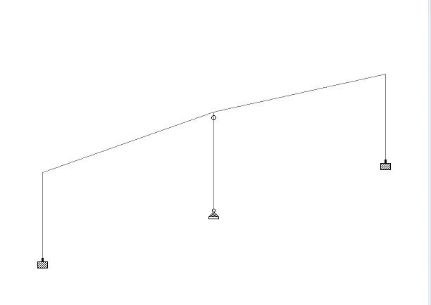
MODEL
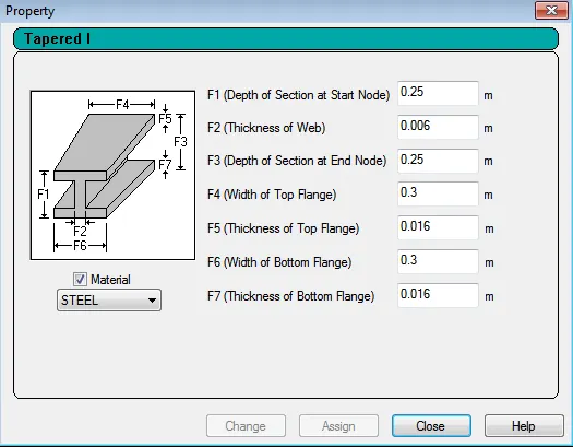
DEFINING OF TAPER SECTION
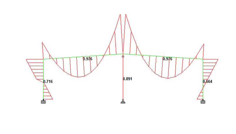
UTILITY RATION CHECK
- Determining Wind load for certain category and condition as per IS 875 Part 3 :2015
An Industrial building of plan dimension 10m x 5m to be constructed (as in Figure below). Building is situated in Chennai. Find the wind pressure on the wall of the building. Assume wall opening as 15 %. Bay spacing = 2.5m.
- Ans: The wind load is calculated as follows:
The project is located in Chennai thus the basic wind speed (Vb) is 50m/s
Total length of the building id 10m, width of building is 5m and the height of the column is 6m.
Risk factor k1 = 1 (it is designed for 50 year life span of the structure) (from table 1 of IS 875 part 3)
The terrain category in this project is category 2. Therefore K2 for 6m height = 1(from table 2 of OS 875 part 3)
K3 the topography factor as per IS code is 1
K4, the cyclone factor = 1.15
Design wind speed (Vz) = Vb*k1*K2*k3*k4
= 50*1*1*1*1.15
= 57.5m/s
Design wind intensity (Pz) = 0.6*(Vz^2)
=0.6*57.5^2
=1983.75N/m^2 = 1.983kN/m^2
Wind directionality factor kd=1
Area averaging factor ka = 0.83
Combination factor kc= 0.9
Design wind pressure = Pz*kd*ka*kc
=1.983*1*0.83*0.9
=1.48kN/m^2
For 6m column height the pressure = 1.48*6 = 8.88kN/m
Internal pressure coefficient = +-0.5
External pressure
|
DEGREE |
DIRECTION |
COEFFICIENT |
|
0 |
EF |
-0.9 |
|
0 |
GH |
-0.4 |
|
90 |
EG |
-0.8 |
|
90 |
FH |
-0.4 |
- Find support reaction for given load. Static check problem
Mono sloped structure (20 degree) of width 10 m & length 30 m with bay spacing of 6 m having no wall sheeting (fully open all around) has following loads. Model the structure in STAAD. Apply Dead load, Live Load & Wind load on the structure and find the support reaction. Also perform static check if the total load applied on the structure is captured in support reaction for each load case.
Self Weight factor – 1.1
Roof Sheet loading = 0.5 kN/m2
Purlin load = 6 kN/m2
Live Load on Roof = 1.5 kN/m2
Wind Load on rafter (Pressure) = 2 kN/m2
Ans: MODELLING PROCEDURE
- As soon as the STAAD software is opened the analytical model is selected and then the units that are used for load and distance measurement are selected and then the file is saved at the appropriate location.
- Next the nodes are created with the help of the structure node option that appears at the right side of the screen. In that the co-ordinates are entered in the format of X, Y, Z system. Where the X is along the horizontal direction and Y is along the vertical direction and Z is also along the horizontal direction. For example if the node as to be created at a distance of 5m in the X direction then the co-ordinated would be 5, 0, 0. The same procedure is adopted to model the entire frame. In case of repetitive distance measurement then the particular node is selected and the transitional repeat option is used to repeat the number of operation.
- Then these nodes are connected with each other with the help of the add beam option which helps to create the beams and columns and rafter. The beams are connected as per the requirement. The beams can also be repeated with the help of the transitional repeat option or with the help of the copy beam option.
- Thus the structure that is required is modelled. The extra beams that are not required are deleted.
ASSIGINGING MEMBER PROPERTY AND SUPPORT PROCEDURE
- In order to assign the member properties to the members select the geometry command, under that select the property command. A dialogue box appears. In the dialogue box select section data base for the steel structure. Then select Indian. Under that the various sections that are available in the market are displaced.
- After selecting Indian it provides various sections for all shapes of the sections. The different shapes available in the steel sections are I sections, Angle sections, Channel sections, Tube sections etc.
- The members that are required for the structure are selected and then the add option is selected which appears at the bottom of the window.
- In the same manner all the member properties that are required from the different shapes are add to the chart.
- Then each member property is selected and it is assigned to the members as per the question given. For example ISMB500 has been asked to assign to the columns. The property ISMB500is selected first and then the columns are selected.
- After that the assign to the selected beams option is selected which appears below the dialogue box is selected. Thus the property ISMB500 is assigned to the columns.
- Then the support to the columns should be assigned. Under the geometry section Support command is selected. A dialogue box appear, in that create option as to be selected. Then the dialogue box with various support conditions appears like fixed, pinned etc. as per the requirement fixed and pinned support condition are to be selected and then the add button is clicked.
- The fixed support are assigned to the exterior columns and the pinned support are assigned to the interior columns.
DEFINING LOAD AND LOAD COMBINATION PROCEDURE
- In order to define the loads go to the loading option under geometry and select the load case option and define the loading types as dead load and live load. Name dead load types as DL and live load type as LL
- Now select DL and click on the add button to add that comes under DL. As per the given question the DL are 1.53kN/m for rafter and LL of 0.375kN/m for rafter.
- For 1.53kN/m and 0.375kN/m select the command as uniform force from the loading command and enter the value of the load with negative sign so that the load acts in the downward direction.
- Click on the load to be assigned and then select the member for which the particular load as to be assigned and the select the assign to the selected beams or nodes.
- In order to define the load combination select the command option and under command option select loading, under loading there is a option called load combination select that. Then the dialogue box appears with the load that we have defined. Select DL and LL and give the factor as 1.5 for both DL and LL. Save the combination with appropriate name.
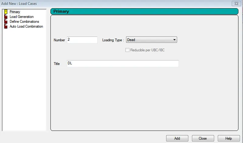
- DEFINING DEAD LOAD (DL)
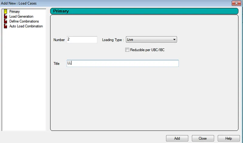
- DEFINING LIVE LOAD (LL)
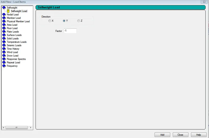
- DEFINING SELF WEIGHT
The height of the top of the rafter = tan(20)*5 = 1.82m
Dead load on the roof = 0.5*10 = 5kN/m
Assume purlin to purlin spacing to be 1.2m
Purlin load = 6*1.2 = 7.2kN/m
Live load on the roof = 1.5*10 = 15kN/m
Wind pressure = 2*6 = 12kN/m
Static load check
Total dead load on the structure = load on the purlin + load on the roof
= 7.2*30*11 + 5*10.642*6
=2695.26kN

Total live load on the structure = load on the roof
= 15*10.642*6
=957.78kN

Conclusion:
From the project carried out it can be concluded that the concept of the modelling of a PEB structure and the application of the loads and defining of the load combination to the structure as per the given data with the use of the STAAD software is learnt. The procedure that is followed while assigning the loads to a structure is known. The method that as to be adopted for fixing up the errors and the warning are also learnt. The static check that is to be done with both the manual calculation the from the software is also learnt.
Vijayalakshmi S H