Week 10 Challenge
AIM & INTRODUCTION:
To Calculate the snow load accumulated in the bridge.
Given Data:
*Span of the bridge is 10m .The snow is settled snow.
*he deck of bridge is flat with B <30 degree.
*The depth of accumulation of snow is 1250 mm.
Snow Load:
* Bridge structures are subjected to snow load when is the bridge is located in a snowy region or cold climate countries.
* The snow load is calculated as per IS 875 Part IV and loads are applied in accordance with IRC 6.
* The minimum snow load considered for design of bridge is 900Kg/m^3 as per clause 224 IRC 6.
PROCEDURE:
Calculations:
*Density of Settled Snow =3KN/m^3.
*Depth of Snow=1.25m.
*Flat deck, angle β=0 Degree.
* Span of the Bridge=10m.
*Snow Load ,So=Density of Settled Snow *Depth of Snow*Span of the Bridge.
=3*1.25*10
So=37.5KN/m.
Shape Coefficient from IS 875 Part IV,
For angle β<30 degree,μ=0.8
Design snow load,S=μ*So
=0.8*37.5
S=30KN/m.
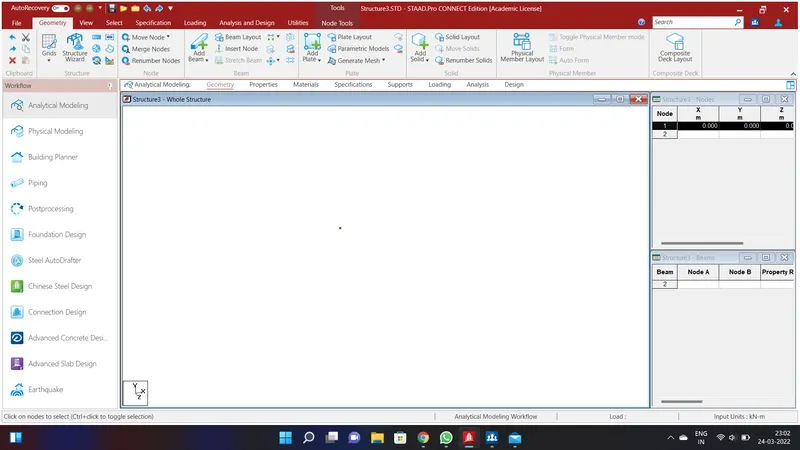
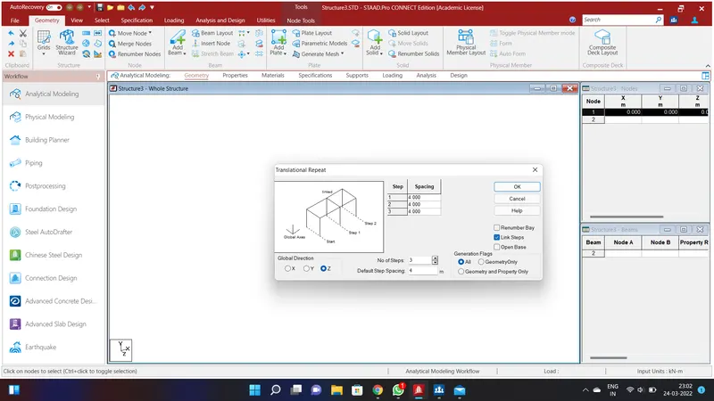
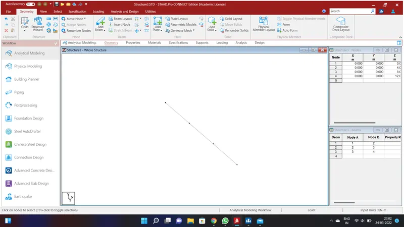
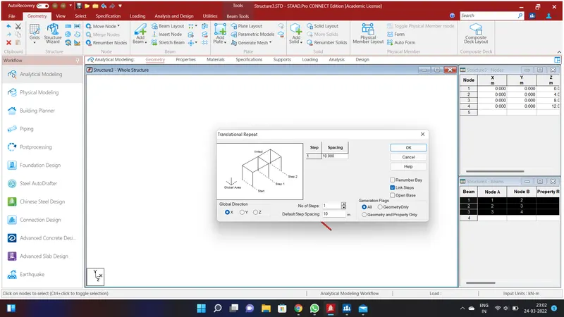
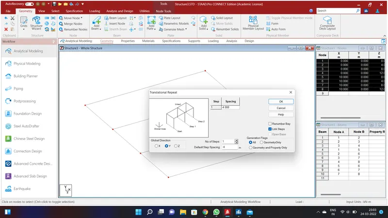
Create a node by assigning the values of Node 1 as X=0;Y=0;Z=0 . Go to select option and select the Node Cursor and select the node and go to Translational Repeat in Global Z Direction and give the values as No. of Steps=3;Default Step Spacing=4m and click Link Steps and click OK. We will have created a width of 12m.To create a span throughout the bridge go to slect option and select the Beam Cursor and select all the Beams and again go to Translational Repeat in Global X Direction and give the values as No. of Steps=1;Default Step Spacing=10m and click Link Steps and click OK.We will have created a bridge of width 12 m and Length 10m.
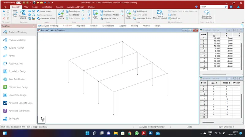
Select the node cursor in the select option and select all the nodes in the bridge go to Translational Repeat in Global Y Direction and give the values as No. of Steps=1;Default Step Spacing=-4m and click Link Steps and click OK.We will have created a pier of size 4m.
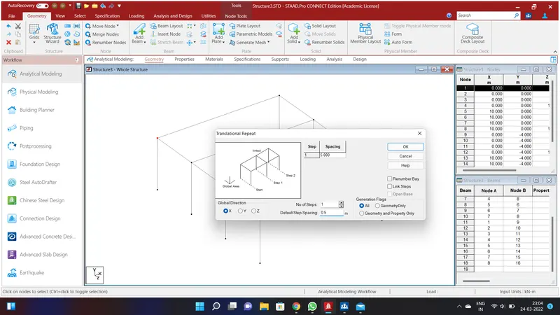
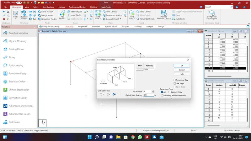
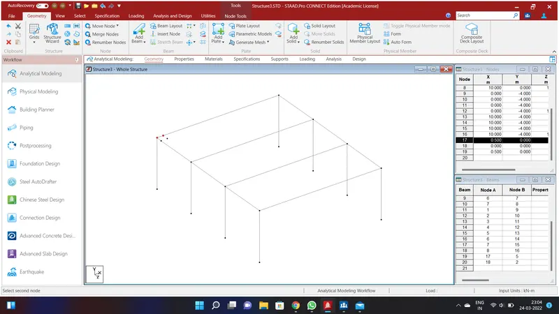
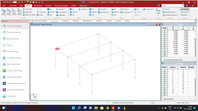
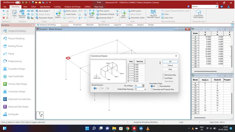
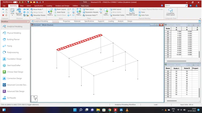
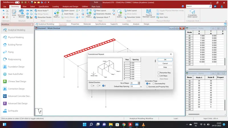
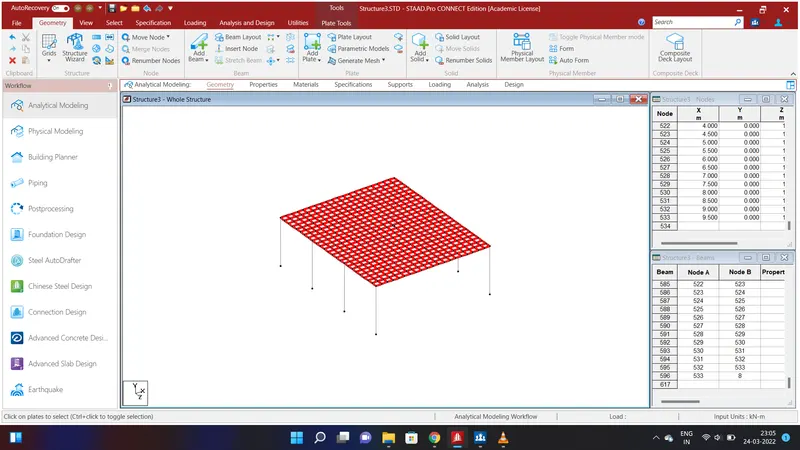
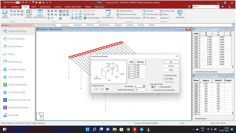
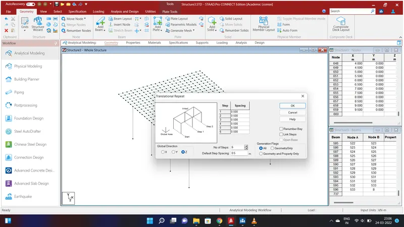
Now we shall craete a Deck Slab . To do that select the node cursor in the select option and select the first nodes in the bridge go to Translational Repeat in Global X Direction and give the values as No. of Steps=1;Default Step Spacing=0.5m and click OK. We will have created two node of size 0.5m. Again select the nodes and go to Geometry option and select Translational Repeat in Global Z Direction and give the values as No. of Steps=1;Default Step Spacing=0.5m and click OK. We will have created four node of size 0.5m.Go to Add Plate in the Geometry Option and connect the four node and go to plate cursor in the select option and click the plate. A plate of size 0.5m will be created .To apply the plate throughout the deck slab again select the plates and go to Geometry option and select Translational Repeat in Global X Direction and give the values as No. of Steps=19;Default Step Spacing=0.5m and click OK. Again go to Geometry option and select Translational Repeat in Global Z Direction and give the values as No. of Steps=23;Default Step Spacing=0.5m and click OK.We will have created Deck slab plate throughout the beams. In the given above problems there is extra 3 m slab on the both side of the width. To create those slab select the plates in the 1st row along the span and go to Geometry option and select Translational Repeat in Global Z Direction and give the values as No. of Steps=6;Default Step Spacing=-0.5m and click OK.To do it on the other side again go to Geometry option and select Translational Repeat in Global Z Direction and give the values as No. of Steps=6;Default Step Spacing=0.5m and click OK.
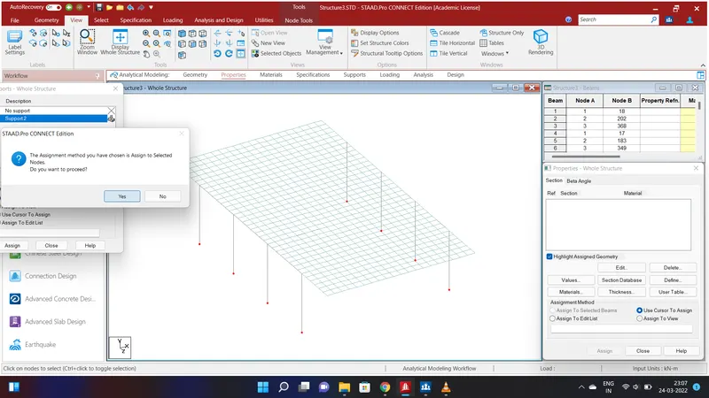
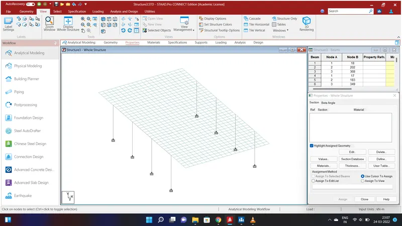
Now we shall assign fixed support to the piers . To do that go to select the node cursor in the select option and select the pier nodes in the bridge go to Specification Option and select Fixed and Add and select Support 2 and select all the nodes and click Assign to selected Nodes and Assign and click YES.We will have assigned fixed support to all the piers.
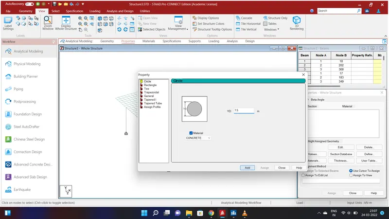
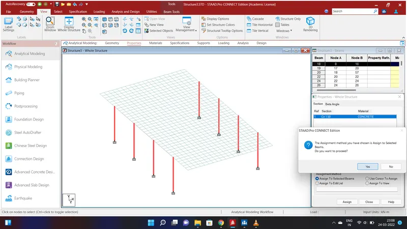
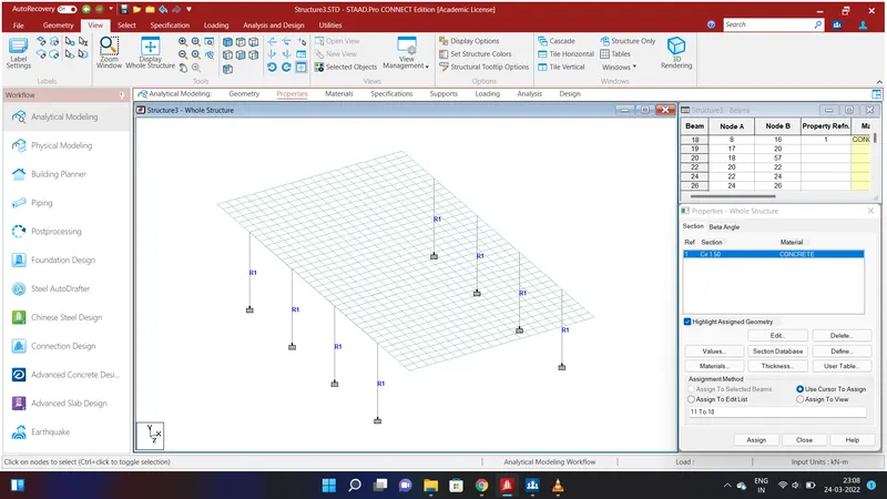
After creating the bridge structure we shall assign properties to the structure. To do that go to Specification Option and select Prismatic and go to Circle and give the values of YD=1.5m using Concrete Material and Add. Now select all the piers and click Assign to selected Beams and Assign and click YES.We will have assigned properties to all the piers.
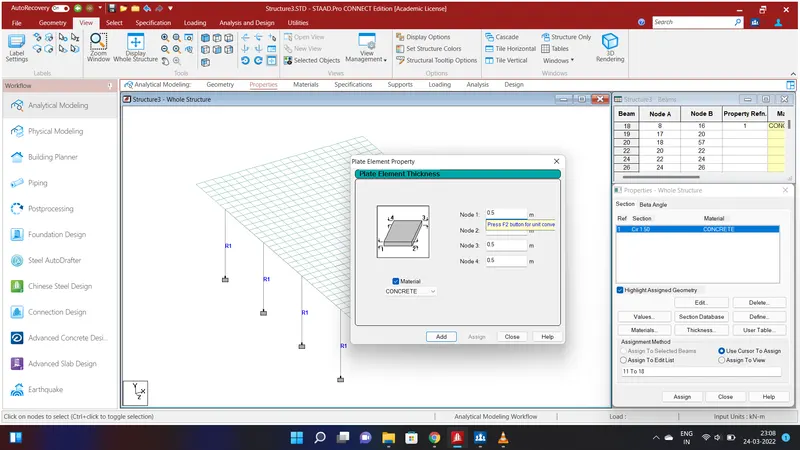
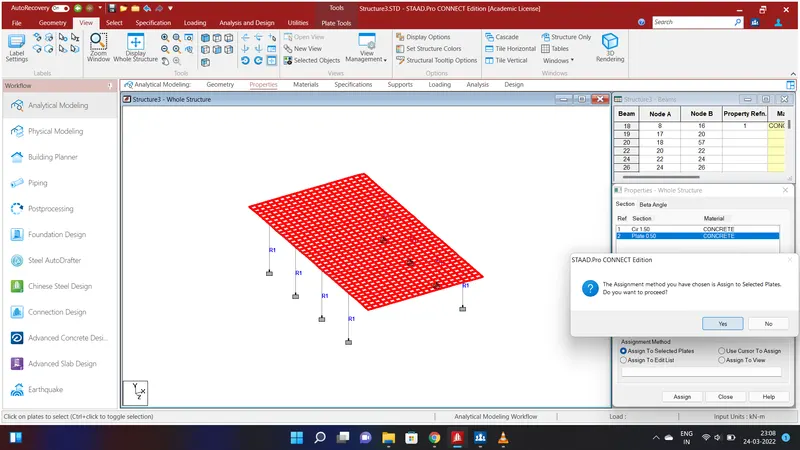
We shall assign properties to the Deck Slab. To do that go to Specification Option and select Plate Thickness and give the values of Node 1=0.5m;Node 2=0.5m;Node 3=0.5m;Node 4=0.5m using Concrete Material and Add.Now select all the deck slab using plate cursor and click Assign to selected Plates and Assign and click YES.We will have assigned properties to the Deck Slab.
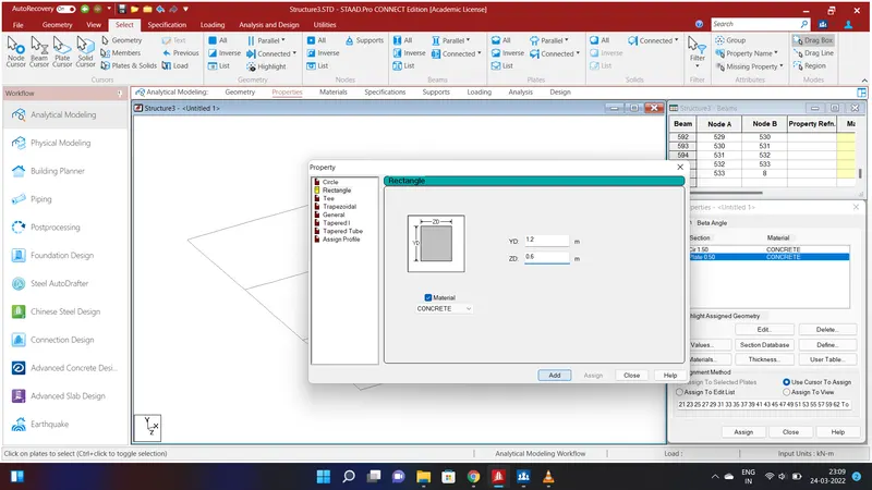
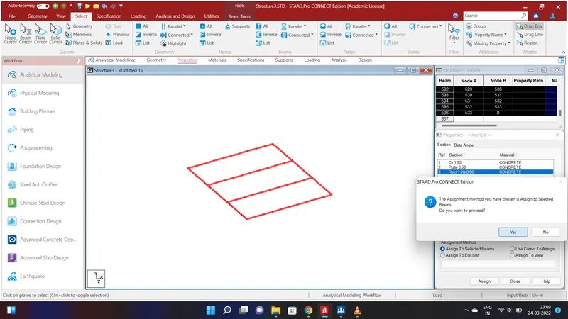
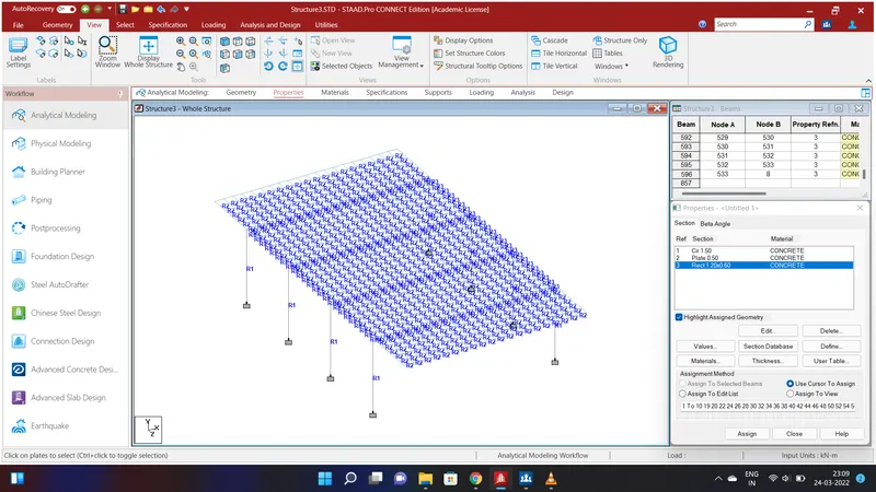
We should apply properties to the Beams of the structure. To do that go to select option and click Missing properties and select the missing properties . Now all the beams will be displayed. Right click the cursor and select new view and clcik OK. Now go to Specification Option and select Prismatic and go to Rectangle and give the values of YD=1.2m;ZD=0.6m using Concrete Material and Add. Select all the Beams using beam cursor and click Assign to selected Beams and Assign and click YES.We shall have assigned all the properties to the entire Bridge.
RESULT:
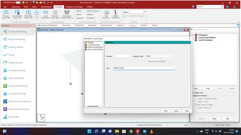
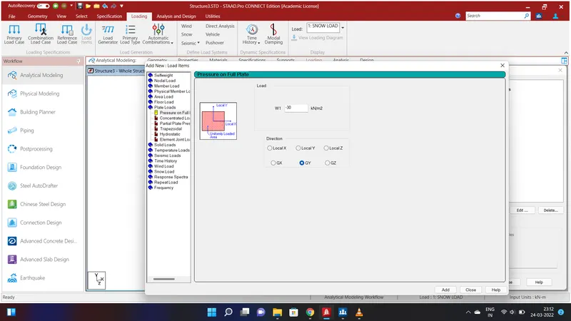
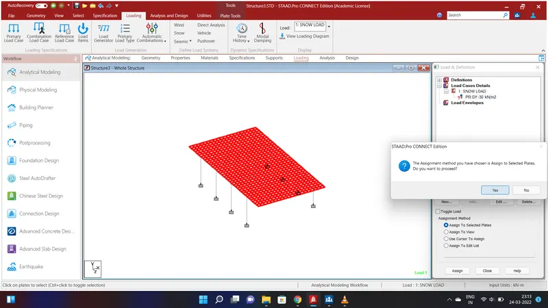
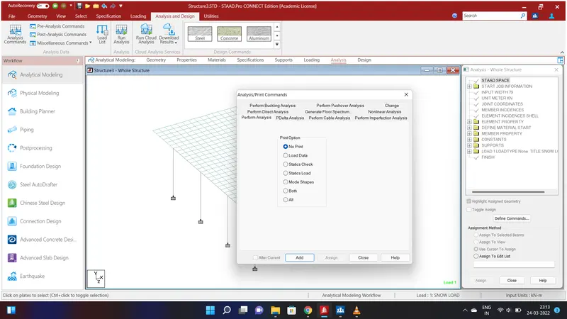
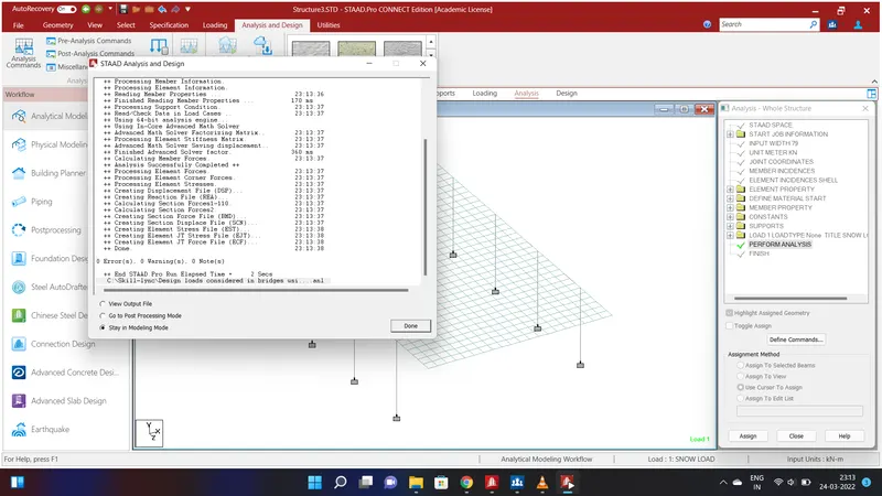
After assigning all the properties go to Loading menu and select Load Case Details and click Add. Give the Title as SNOW LOAD and click Add. Again select the SNOW LOAD and click Add and go to Plate Load and select the Pressure on Full Plate and give the value of W1=-30Kn/m^2 in Global Y Direction and click Add. Now go to select option and select all the plates and clcik Assign to Selected Plates and Assign and click YES. The snow load will be applied throughout the deck slab.Now save the structure and go to Analysis and Design and clcik Add. Run the analysis and go to Post Proccessing mode to acquire the Report.
REPORT:
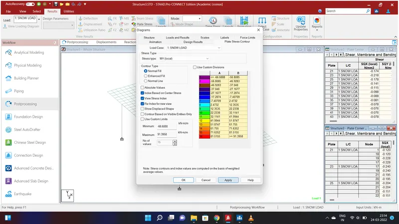
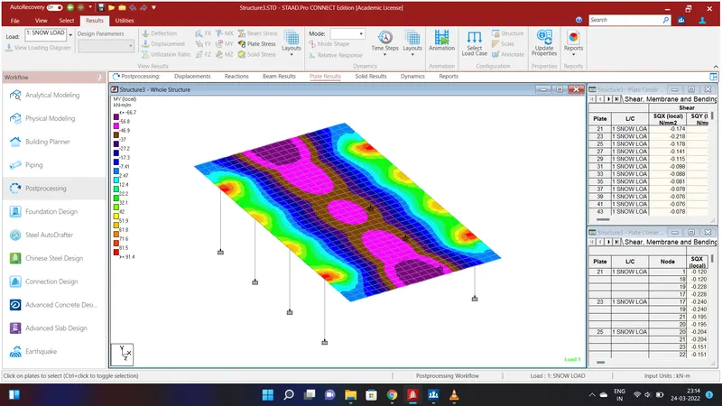
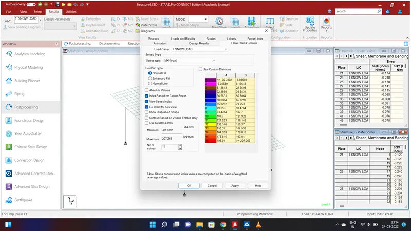
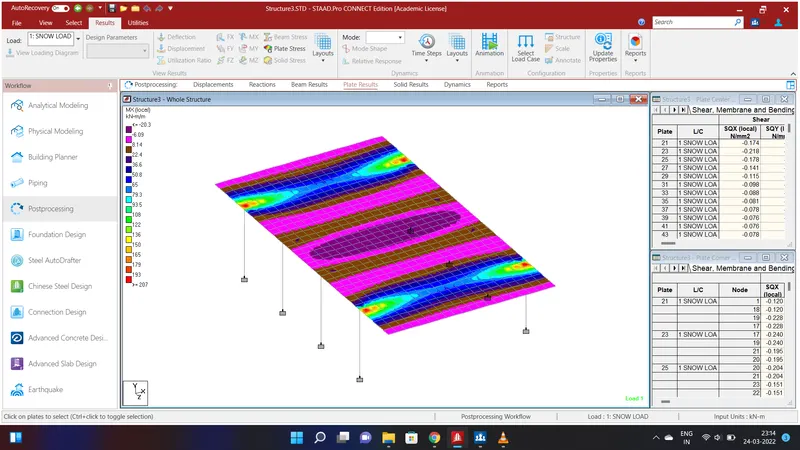
To get the plates result go to plate result and give the Stress Type as MY(Local) and Apply. Do the same to get the result of MX(Local).
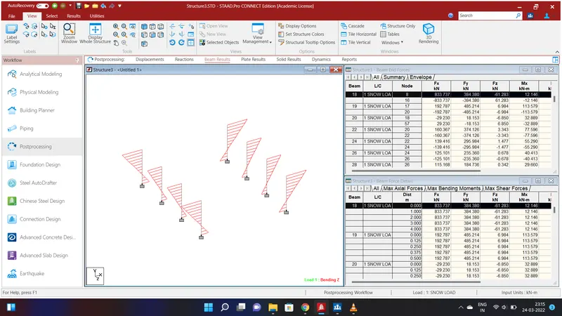
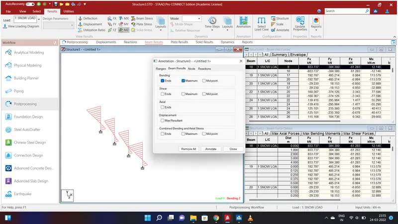
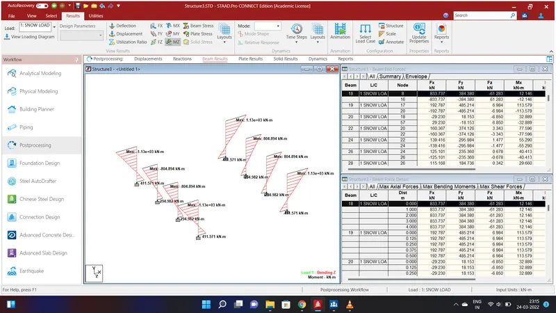
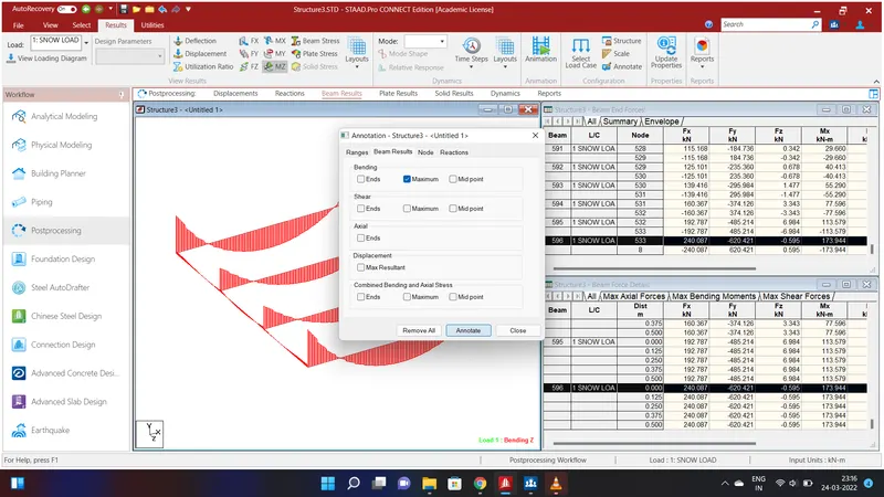
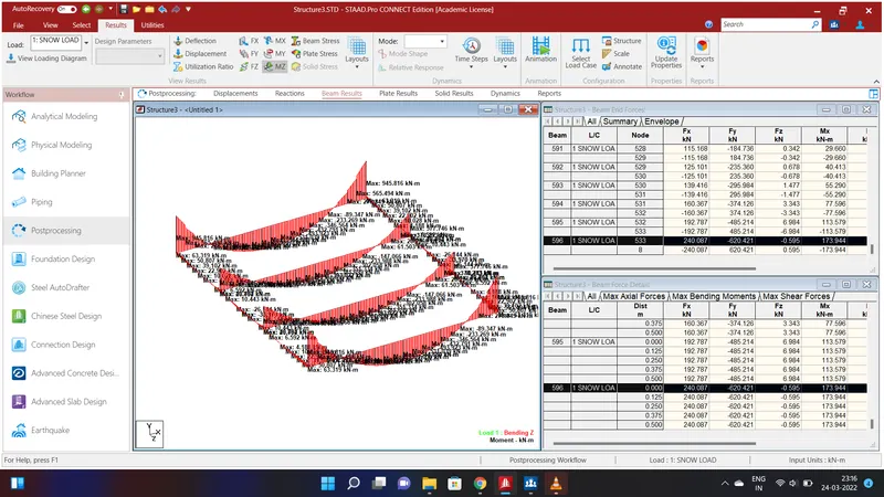
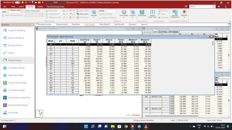
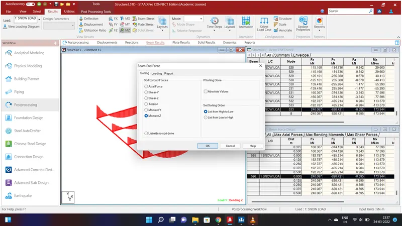
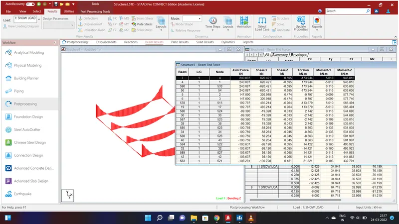
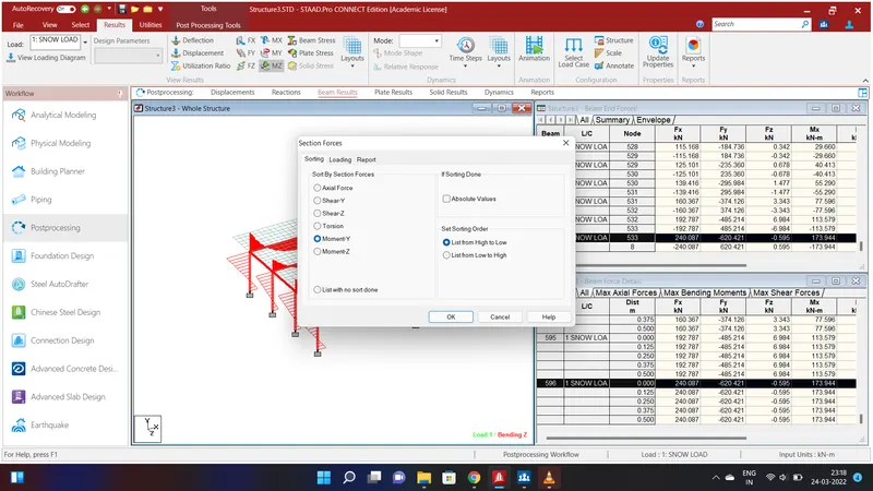
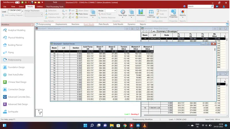

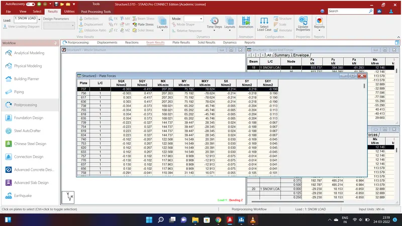
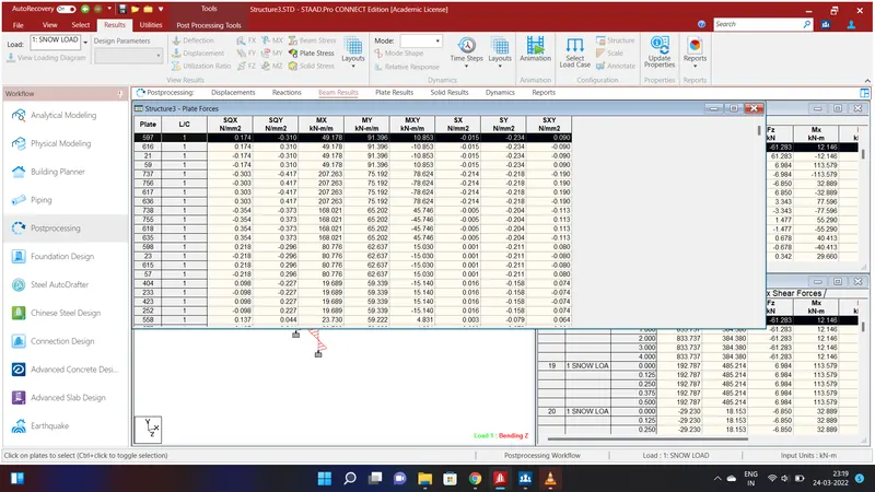
The report is obtained for the Bending Moment at X & Y and also Beam end Forces to X&Y.