Week 10 Challenge
AIM and INTRODUCTION :
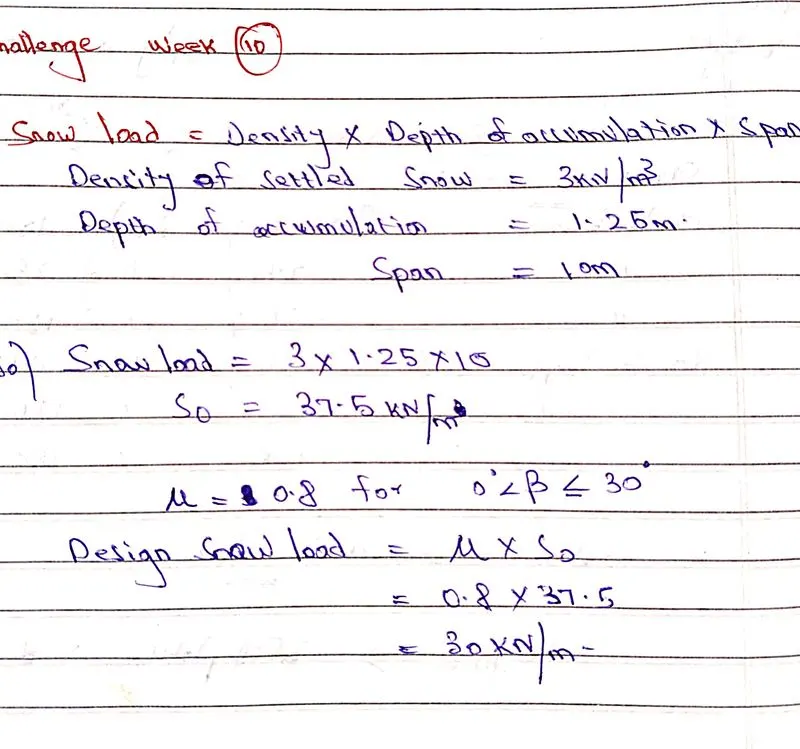
- To calculate the settled snow load accumulated on the bridge of span 10m and to apply the calculated snow on the bridge using staad pro and to perform structural analysis.
- snow loads are more common in regions where snowfall occurs and regions where colder climate prevails.
- snow load is calculated as per IS 875 part four and also loads are applied as per IRC 6
- The minimum load considered should be 900kg/m3 as per clause 224 IRC 6.
- The design snow load S = μ * s0.
- The density of snow load varies according to its settlement over structure.
- New snow = 50 - 70 kg/m
Damp new snow = 100 - 200 kg/m3.
settled snow = 200-300 kg/m3.
depth hoar = 100 - 300 kg/m3.
wind packed snow = 350 -400 kg/m3.
firn = 400 830 kg/m3.
very wet snow = 700 - 800 kg/m3.
Glacier ice = 830 - 917 kg/m3.
- Based on the slope condition the snow load classified into
>> Positive roof slope.
>> Negative roof slope.
>> Multilevel roof slope.
PROCEDURE :
- snow load calculation and step-by-step procedure
The staad pro design steps are as follows :
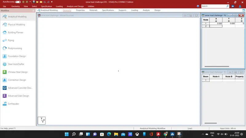
- In this challenge the first step we need to enter the coordinates of nodes, give the coordinates for the pier.
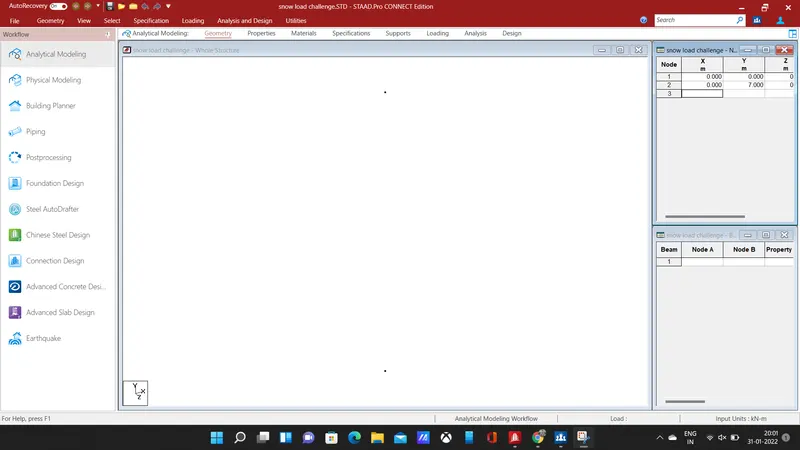
- The nodes been added, connect the nodes by beam using added beam command, thus a pier has been created for the structure.
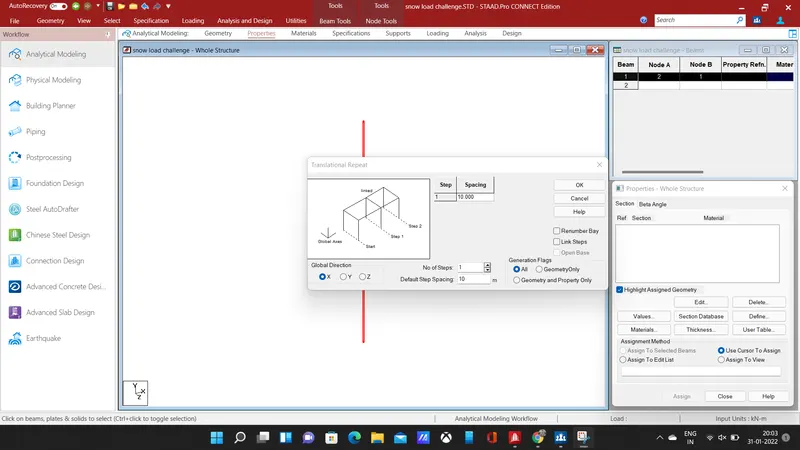
- After adding pier, copy the beam in the x-direction at a spacing of 10m with steps as 1 using translational repeat command, the 10m indicates the span of the bridge, another pier will be formed, connect the two piers by adding beam.
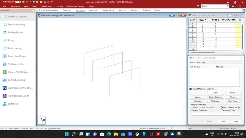
- Then repeat the piers in z-direction for 3 steps at a spacing of 5m each, using translational repeat command, an another 3 sets of piers and beams has been created.
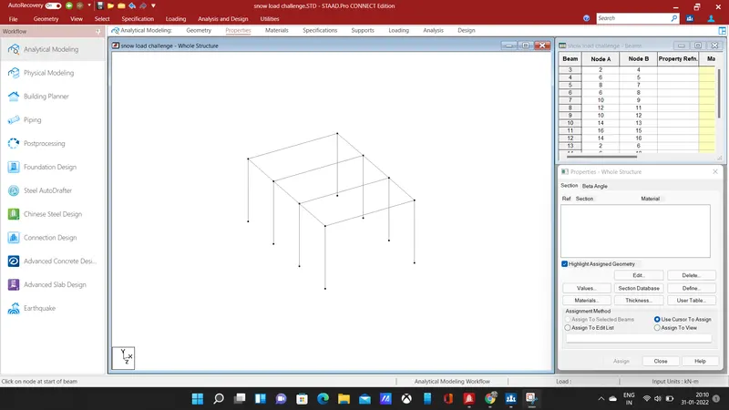
- link the piers and beams by using add beam command, next step is to add a deck to the bridge for that we need to add plate elements.
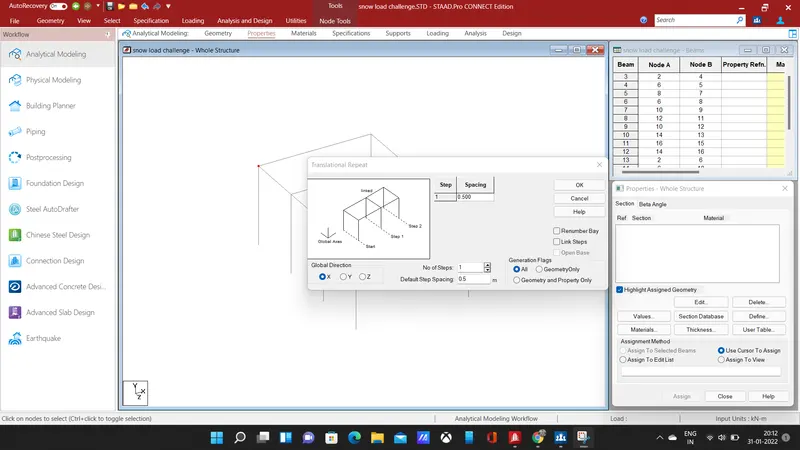
- copy the corner node and repeat the node for a step in x-direction at a mesh size of 0.5m using translational repeat command, an another will be created.
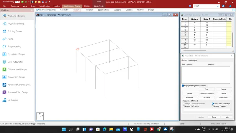
- copy the two nodes in the z-direction at the same mesh size of 0.5m for one step, connect the four nodes using add plate command, then we need copy the plate in x and y direction.
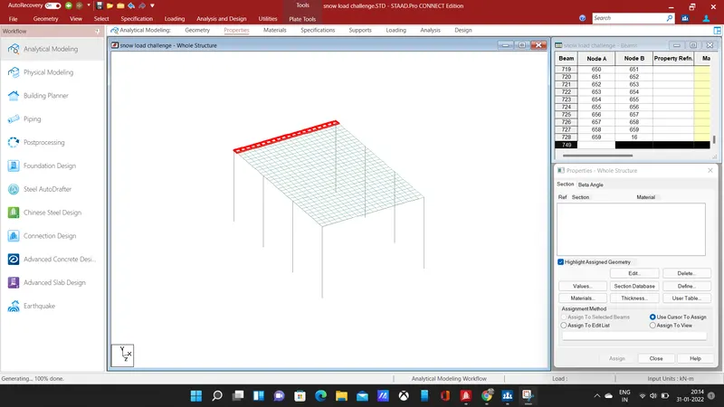
- copy the plate in the x-direction for 19 steps at a spacing of 0.5m, the plates will be added in the x-direction for the entire 10m span of the beam, after the copy the plates in z-direction for creating the deck for the bridge structure.
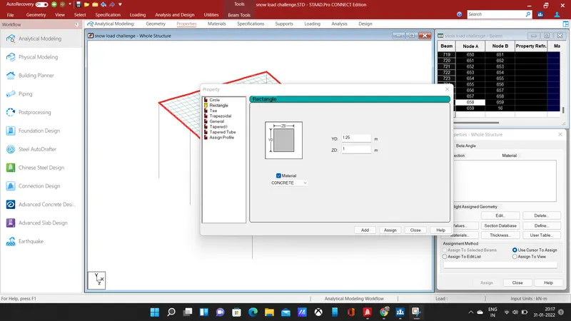
- next step is we need to specify the properties for the beams, piers, and plates, add a rectangular section and assign it to the longitudinal beams, and cross beam on either end of the bridge.
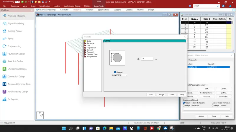
- Add a circular section of 1.5 m and select the piers, click on the assign to selected beams button and select the assign button, the property will be assigned to the piers.
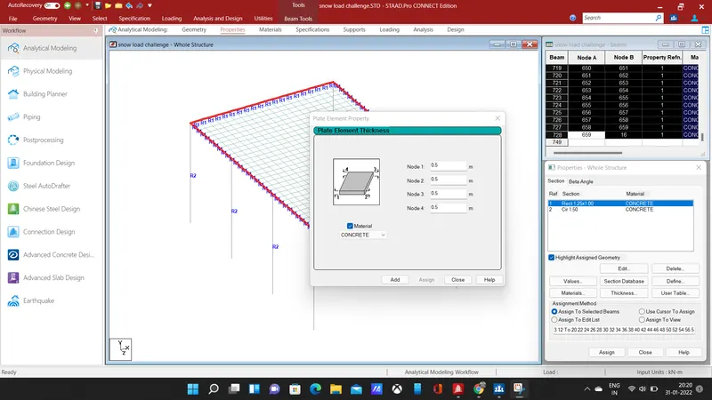
- Next, specify the thickness of the plates in the deck slab, add a plate thickness of 0.5 m, then assign the property to the plate.
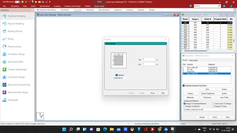
- add a rectangular section of required breath and depth, select the cross beam and assign the property to the beams.
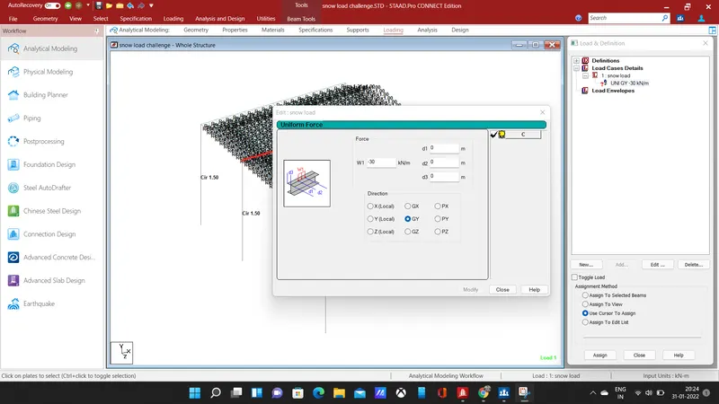
- The next step is to give loading to the bridge structure, add a load case and give title as snow load, give the load as uniform force, enter the calculated load value with the negative symbol in the global y-direction.
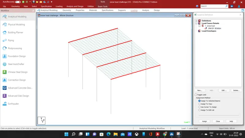
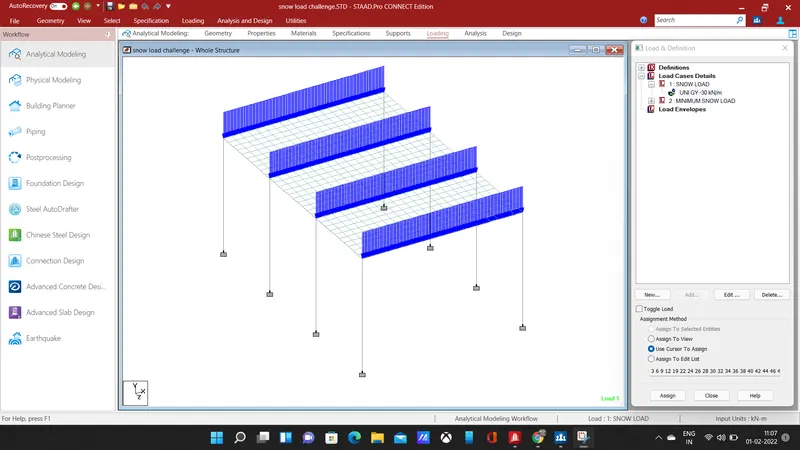
- select the cross beams and apply the snow load to the beam.
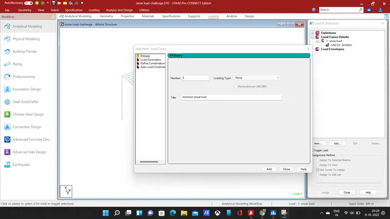
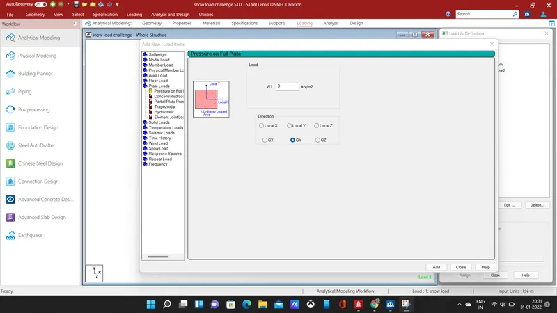
- next, we need to apply the minimum design load in the deck slab, select the plates and apply the load in the global y-direction with a minus symbol indicating the load acting downwards.
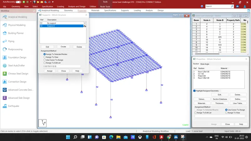
- Assign fixed support to the piers, select the piers and assign it.
RESULT:
- After loading, we need to analyze the structure, click on analysis and design command select run analysis, the staad pro will check for errors, after that click on post-processing mode for further analysis of the structure
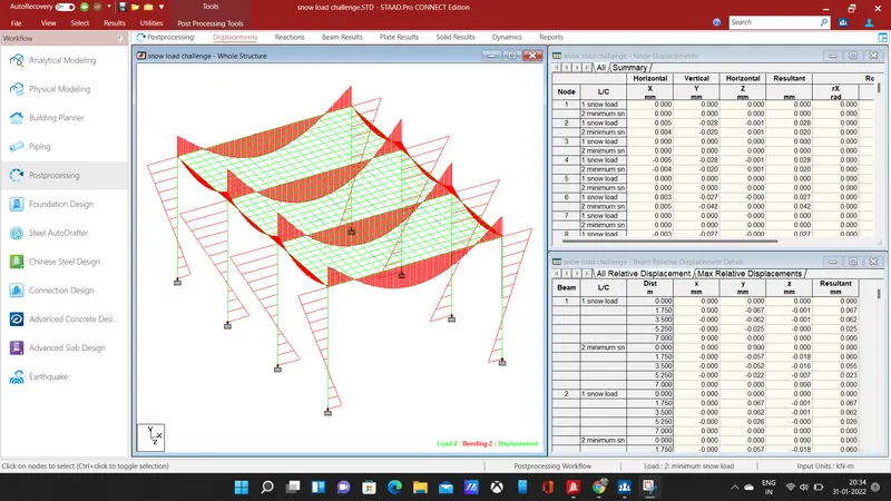
- In the post-processing, mode click on the results tab, select mZ for loading load, the bending moments of the structure has shown above.
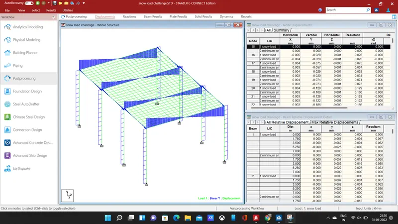
- The shear force in y-direction for the design load has been above.
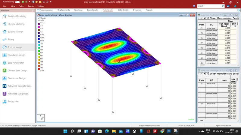
- select the plate stress and select the stress type as mY for load 1, the results will be detailed in contour image form.