Week 10 - Challenge 3 - Door Trim Lower with Engineering Features
Objective:
To create the Door Trim Lower Plastic component through the given Class-A surface. To begin with, the tooling axis for the given Class-A Surface should be created meeting the requirements of the draft angle and at the end perform the Draft analysis on the model.
To create the Heat Stakes and the locators considering the design rules mentioned in the video for the door applique.
Take the Thickness of the component to be 2.5 mm.
Class A Surface:
Class A surface is the aesthetic skin data for the automotive part designing and curvature surface to represent the main component. Before proceed with A surface to analyze the Draft angle, if get any mismatch surface reconstruct the A surface.
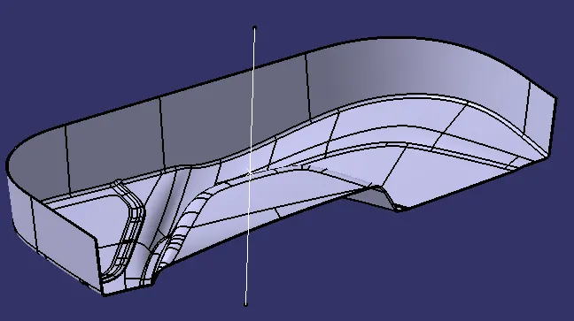
Given class A surface
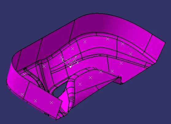
STEP 1 : Validate the connectivity of the Class A Surface. Verify there is no gap between the components by using the Joint or Boundary command.We may verify it either visually or by use the boundary command.Its three boundaries are two inner and one outer circular bounds.Since it looks that the surface has a gap if there is a green border between, the first check was completed.
Tooling Axis:
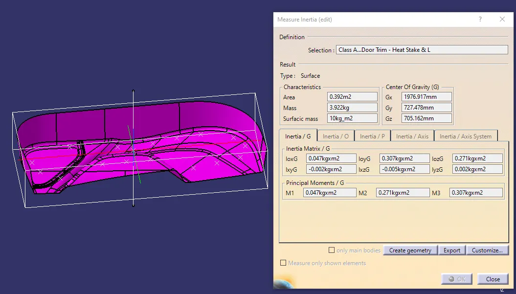
Tooling axis also known as tooling direction, is the primary factor to take into account when considering plastic and mold parts because it determines how the mold part moves and the likelihood that the plastic component will emerge from the mold part (Core and Cavity). Tooling Direction is the direction in which the mold is opened in a molding machine configuration. The tooling orientation essentially determines which way the mold pulls apart. The mold is constructed from two distinct halves: the core and the cavity. Primary direction is another name for tooling direction.I've made a tooling axis here. Inertia measure is used to find the center of gravity of the surface and then a line is drawn perpendicularly through the center of gravity.
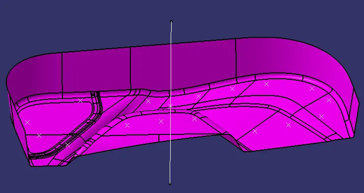
Draft Analysis of Class A Surface:
To find out if the part you drafted will be easy to remove, use the Draft Analysis command. When doing this type of analysis, color-coded zones on the investigated element are used, which correlate to certain values if there is a departure from the draft direction at any point.
- Draft analysis is done to determine whether the minimal draft of three degrees is being maintained after selecting the tooling axis.
- The user may quickly determine the right draft angle of a component by using the Draft Analysis. A draft angle is the degree of taper for cast or molded components that runs perpendicular to the parting line. Draft analysis is appropriate for 3D part models.
- While testing an draft analysis please ensure whether it is in a Material Model or not.shown in below screen shots.
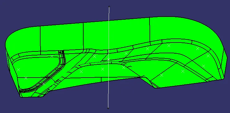
STEP 2 : Draft analysis is required to check if a part has required draft or not. Draft is required so that a part can be ejected from its mold easily.Draft will be Maximum 3 Degree.But For me its passing at 2.9 Deg So i used to make it as 3 Deg As Maximum Level in Class A surface Draft Analysis Method and it is passing at 3 Deg.Make Sure you are in MATERIAL MODE To Check Draft analysis.Use Compass in Tooling AXIS while Drafting.
- In Draft Analysis If it shows Green Colour Surface. its Pass in Drafting.Suppose its shows in Red Colour Surface its Fails in Draft Analysis.its your choice of making Colour code for your convenient.
Class B Surface:
Class B is a reference surface that the design engineer creates and which is a replica of class A at a distance equal to the part's thickness.
STEP 3 : Offset Class A Whole Surface for Creating an Class B Surface. Because of Complicated part can Be Fully Offset to Create Class b surface From Class A.
There are few patches that we are going to work on it.
STEP 4 : For Solving the patches first we are going to remove FILLET area by using JOIN Command with SUB - ELEMENTS TO REMOVE option in JOIN Command.
After Selecting the Fillet surface it Creates an ERROR.To Solve it In JOIN Command You Should Remove or Off Check Connectivity and Check Manifold. and the problem will be solved. FILLETS are Removed.
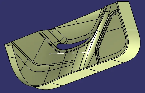
STEP 5 : For Solving The Patches using Multiple Extract Command separate the patched area surfaces and Create a Boundary Line on the Multiple Extracted Surface.Finally Extrapolate It to Interconnect the Both surface for Minimum 5mm Maximum how much you want it to intersect both surface.after interconnected it. and Using TRIM Command trim the Both surface.To get Sharp edge Surface and Finally use JOIN Command To Join The individual Part as a Single Part and EDGE fillet on it. shown in below screen shots.
STEP 6 : After Trimming Use JOIN Command to JOIN the each part as an Single Component.
STEP 7 : Finally Create an EDGE FILLET for 1.44mm,1.2mm,5.25mm.as Shown in Below Screenshots.
STEP 8 : Finally use BOUNDARY COMMAND to check whether there is a gap in between the surface. if there is an gap In between the surface its shows green colour boundary line.only edges should be in Green Colour line.
Class C Surface:
Class C also known as the side wall of the surface, is a reference surface that the design engineer creates to connect Class A and Class B surfaces.
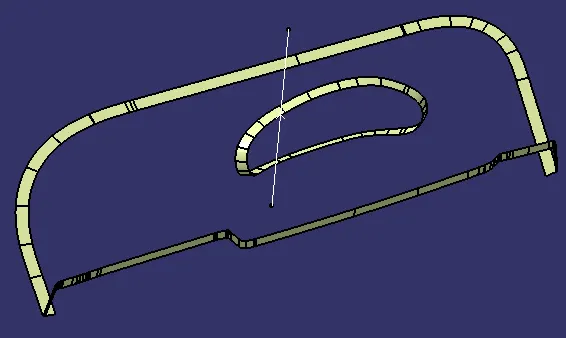
STEP 9 : The boundary was developed by taking class A into account.To build a Class C surface, the sweep command was used for -90 DEGREE and 3 DEGREE,in some area as shown in below Screenshots and as a point of reference Line, the primary tooling axis line and Boundary Line were taken into account. Sweep Command is used to Extend the Border of Class A surface to Vertical direction for Creating Class C surface.
- Boundary: pick the boundary for the next operation.
- Swept: swept the selected boundary.
- Extrapolate: surface can't join properly, so I used to extrapolate those surfaces.
- Join: now join those surfaces with each other and form a single surface.
- Trim: trim those extrapolate surfaces and get a required surface.
STEP 10 : Sweep cant be created perfectly in Fillet and Curve Surface area so we are Creating the Sweep as one by one. in fillet area So we are going to take BOUNDARY LINE & MULTI - SECTION SURFACE command and create a Smooth surface By Connecting the sweep edge surface as shown in screenshots.
Sweep and GUIDE as BOUNDARY. To Create In between Smooth surface and Join it. After Joining Extrapolate and TRIM it.
Class A and Class C Join:
STEP 11 : Finally JOIN CLASS A Surface and CLASS C Surface.and TRIM IT.
Trim Surface:
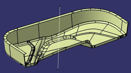
When Creating a Final trim by class a and c surface with class b surface. but it shows ERROR.while Trimming Because of Class B surface is not interconnect with Class A & C surface for trimming.so I am going to take an Boundary and Extrapolate the surface for 0.5mm to 5mm Maximum. to interconnect Class A & C Surface with Class B Surface for Trimming it.
STEP 12 : And use Final Trim for Trimming Class A and C Surface With Class B surface. Finally Surface as been created at 2.5mm gap between Class A and Class B Surface. To form an closed surface with hollow of 2.5mm gap.
STEP 13 : Check Finally There is No any Boundary in the DOOR TRIM LOWER DESIGN surface By using BOUNDARY COMMAND. If there is no boundary it shows Error and your work is clear and perfect. If you find any Boundary line its seems you done ah mistake or wrong surface while joining. So redo it.
Close Body:
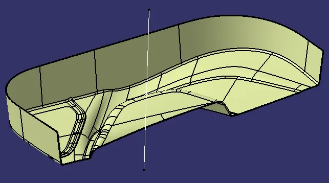
STEP 14 : Finally create a Closed Surface in Part Body By Using CLOSE SURFACE METHOD.
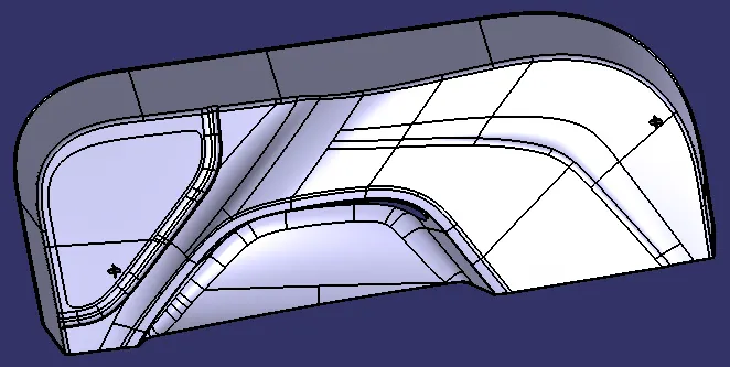
Creation of Engineering features FOR DOOR APPLIQUE :
LOCATORS : A 2-way locating pin restricts motion along 1 axis (or 2 degrees of Freedom), like a round pin in a slot. Likewise, a 4-way pin restricts 4 degrees of freedom along 2 axes. A round locating pin located concentrically in a hole is a common application of a 4-way pin, and helps to further secure the piece.
HEAT STAKES : Heat staking is a process which utilizes pulsed heat to join two or more parts together where at least one part is made out of plastic. It works by heating a plastic part to just above the glass transition temperature while simultaneously applying force so that it is deformed.
STEP 15 : After creating a Closed Solid Surface.To create a LOCATORS & HEAT STAKES. From the Closed Surface Create a POINT on it wherever you want to create LOCATORS and PLANE.after creating point and plane.
Create a SKETCH and Draw a 4 WAY LOCATORS for 15mm Each Side like PLUS SYMBOL.
and PAD it for certain MM in Both sides.
Using DRAFT DEFINITION Draft the 4way Locators for 0.5deg. Neutral Element as Pad Bottom Face and Pulling Direction as Tooling Axis Shown in Below Screenshots.
Create a CHAMFER of 3mm Length/45deg angle in 4 corners of Locators.
Use EDGE Fillet For 0.3mm in 4 way locators edge.
Finally TRANSLATE the Locator Using TRANSLATE Command. Wherever You Want to Locate it.
And Using UNION TRIM REMOVE or KEEP any 1 Option Can be used for trimming Unwanted Surface or part.Same Method for 2 WAY LOCATORS also.
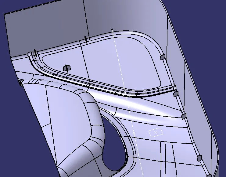
HEAT STAKES CREATION :Heat staking is a process which utilizes pulsed heat to join two or more parts together where at least one part is made out of plastic. It works by heating a plastic part to just above the glass transition temperature while simultaneously applying force so that it is deformed.
STEP 16 : Create a PLANE at POINT.15 and use SKETCH Command to Create an Circle Inner dia 5mm and Outer dia 7mm for Heat stakes.
PAD it for Required mm.
TRANSLATE the Heat Stakes Using TRANSLATE Command. Locate it in given POINTS.
Using DRAFT DEFINITION Draft the HEAT STAKE for 0.5mm DEG. Neutral Element as Pad Bottom Face and Pulling Direction as Tooling Axis Shown in Below Screenshots.
Use EDGE Fillet For 0.3mm For HEAT STAKES EDGES.
Finally TRIM the unwanted surface By using UNION TRIM Command.
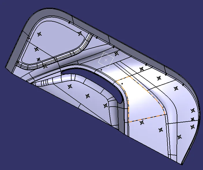
STEP 17 : Final TRIM as been used to Remove Unwanted Part or Extended Locator on the Inside Cylindrical Object to be Removed using UNION TRIM Command.
after Creating union trim FINAL OUTPUT as Been Completed with LOCATORS & HEAT STAKES.
Final Draft Analysis:
STEP 18 : After completing Union Trim and Finally Use DRAFT ANALYSIS METHOD for whole Component.shown in given Below Screenshots.
In Draft Analysis If it shows Green Colour Surface its Pass in Drafting.Suppose its shows in Red Colour Surface its Fails in Draft Analysis.its your CHOICE which colour you want as pass or fail its depend upon you and your convenient.
DRAFT ANALYSIS METHOD is used for DOOR TRIM LOWER .Draft analysis is required to check if a part has required draft or not. Draft is required so that a part can be ejected from its mold easily.Make Sure you are in MATERIAL MODE To Check Draft Analysis.Use Compass in Tooling AXIS while Drafting.
Draft will be Maximum 3 Degree and Minimum 2.5 Deg.But For me its passing at 2.9 Deg So i used to make it as 3 Deg As Maximum Level in (DOOR TRIM LOWER DESIGN) Closed surface Draft Analysis Method. and it is passing at 3 Deg.
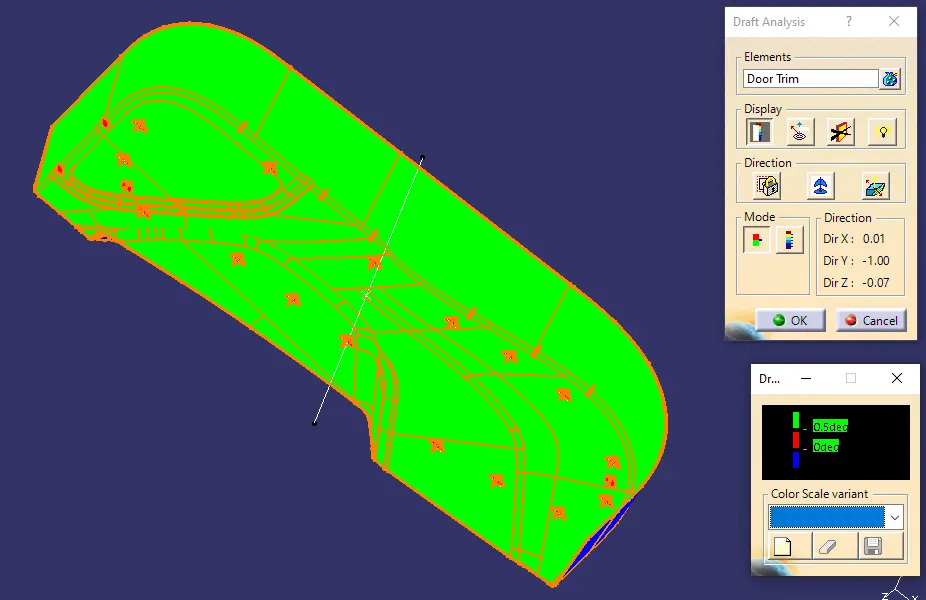
STEP 19 : After Completing Draft Analysis for Closed Surface at 3 deg and Next DRAFT ANALYSIS METHOD is used for DOOR APPLIQUE.Draft will be Maximum 1.45 degree,Minimum of 0.45 degree.For Door Applique Creation.Make Sure you are in MATERIAL MODE To Check Draft Analysis.Use Compass in Tooling AXIS while Drafting.
Tree Structure:
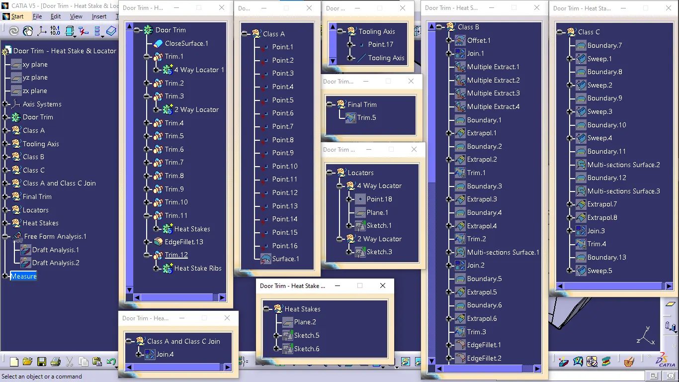
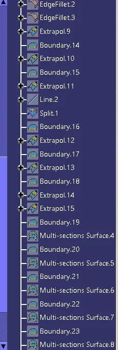
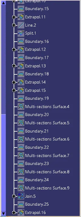
Different Views:
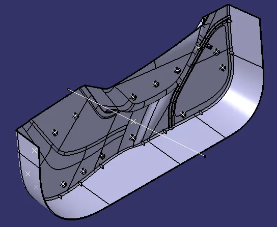
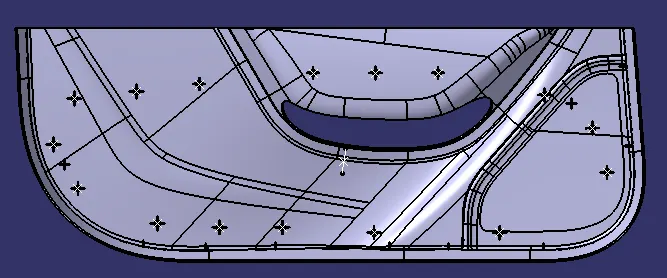
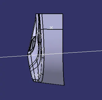
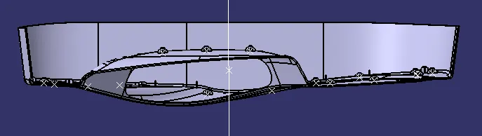
STEP 20 : Finally take a Screen shots of ISO,FRONT,SIDE,&TOP View with and Without Draft Analysis in Final Closed Surface Body.
Conclusion:
- The tooling axis for the given Class-A Surface is created which meeting the requirements of the draft angle.
- Draft analysis is done on the CLASS-A surface.
- Using the Close Surface feature, Solid body is created from the surface.
- Created the DOOR TRIM component, HEAT STAKES & LOCATORS using the given Class-A surface & INPUTS.
- Draft analysis is done on the Final Component.