Week 10 - Challenge 3 - Door Trim Lower with Engineering Features
Aim: - To create a DOOR TRIM LOWER Plastic Component through a given Class A Surface and perform Draft Analysis on the final plastic component.
Create the Heat Stakes and the locators considering the design rules.
Objectives:
- Creation of Tooling Axis.
- Creation of Class B and Class C surface.
- Creating a solid part out of surface modelling.
- Creating Heat Stakes & Locater on the component.
- Draft Analysis of Class A Surface, final plastic component, Heat Stakes & Locater.
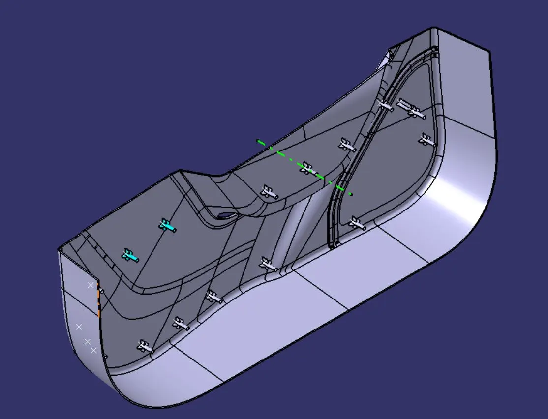
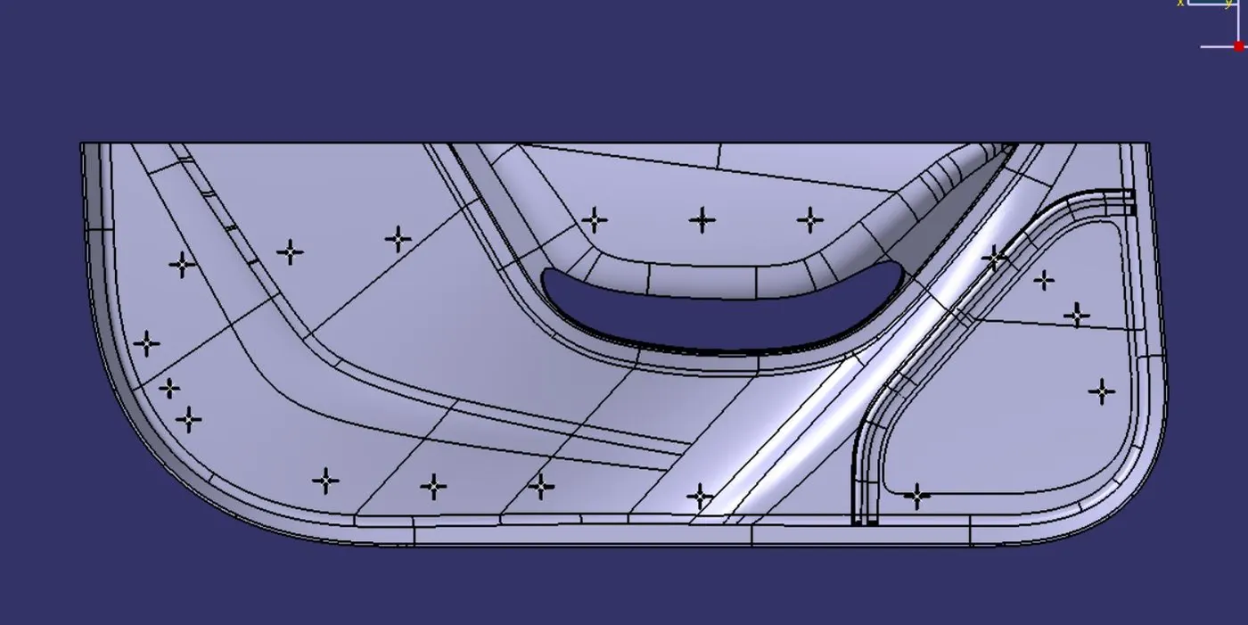
Provided Class A surface for component is shown below:
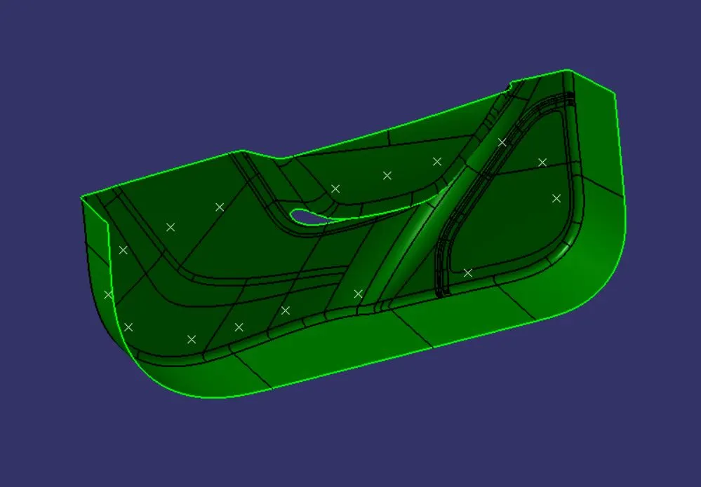
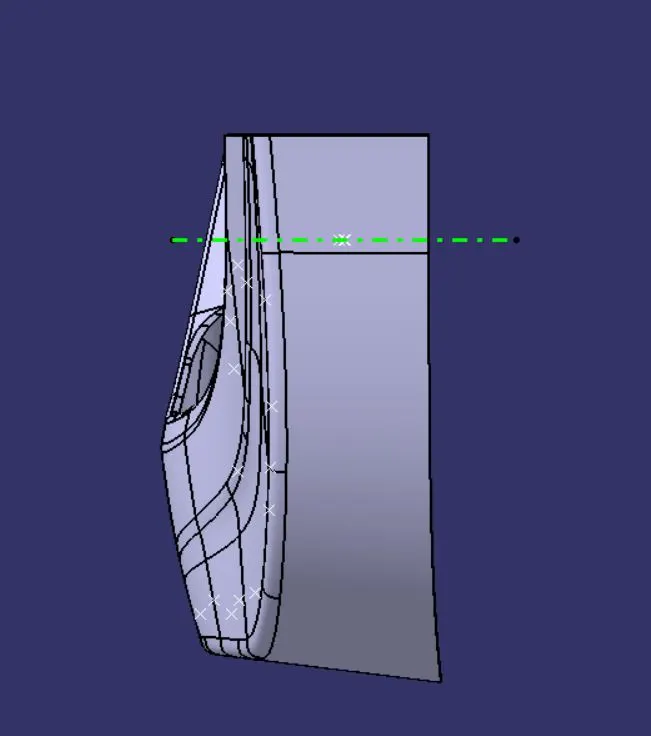
Identifying Tooling Axis
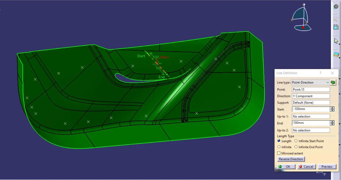
· On inspecting the part, the Y-Axis is the best option for tooling the component.
· As shown below the Tooling Axis is created using Normal to point method.
Draft Analysis of Class A surface is shown below:
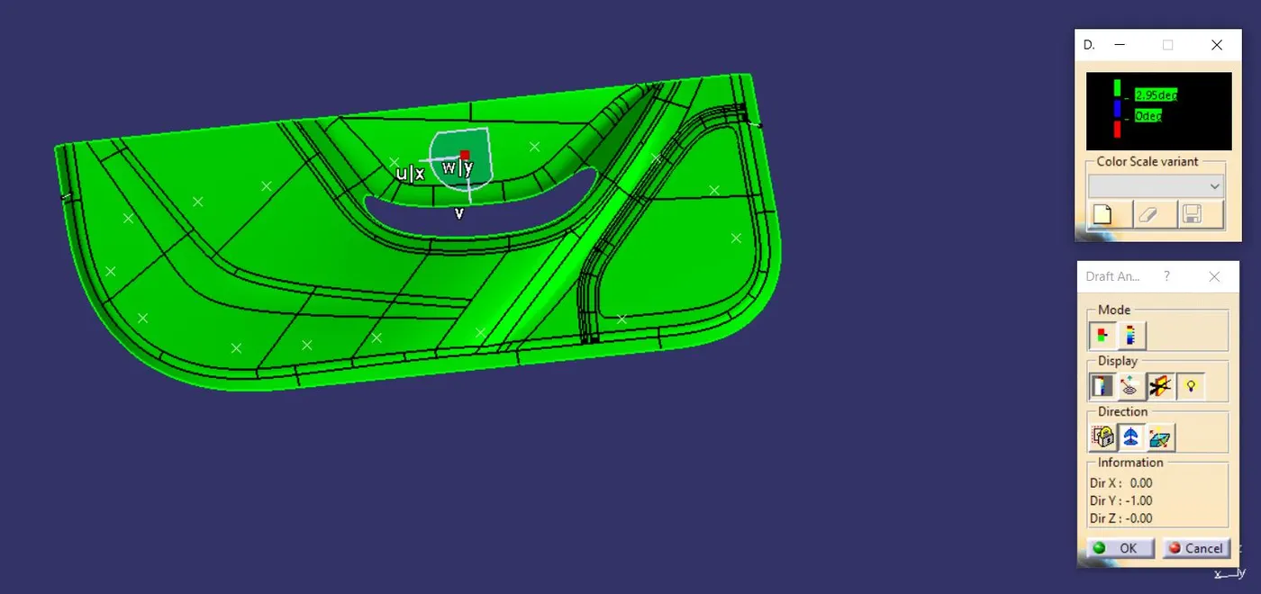
· To manufacture the Tooling component, Draft analysis is done on it.
· Industrial std. is of 3° and as it is seen in the above the draft on provided class A surface is more than the acceptable value.
Creating Surface B
· Using extrapolate and off-set command the surface B is created which is shown in below image of off-set value of 2.5mm.
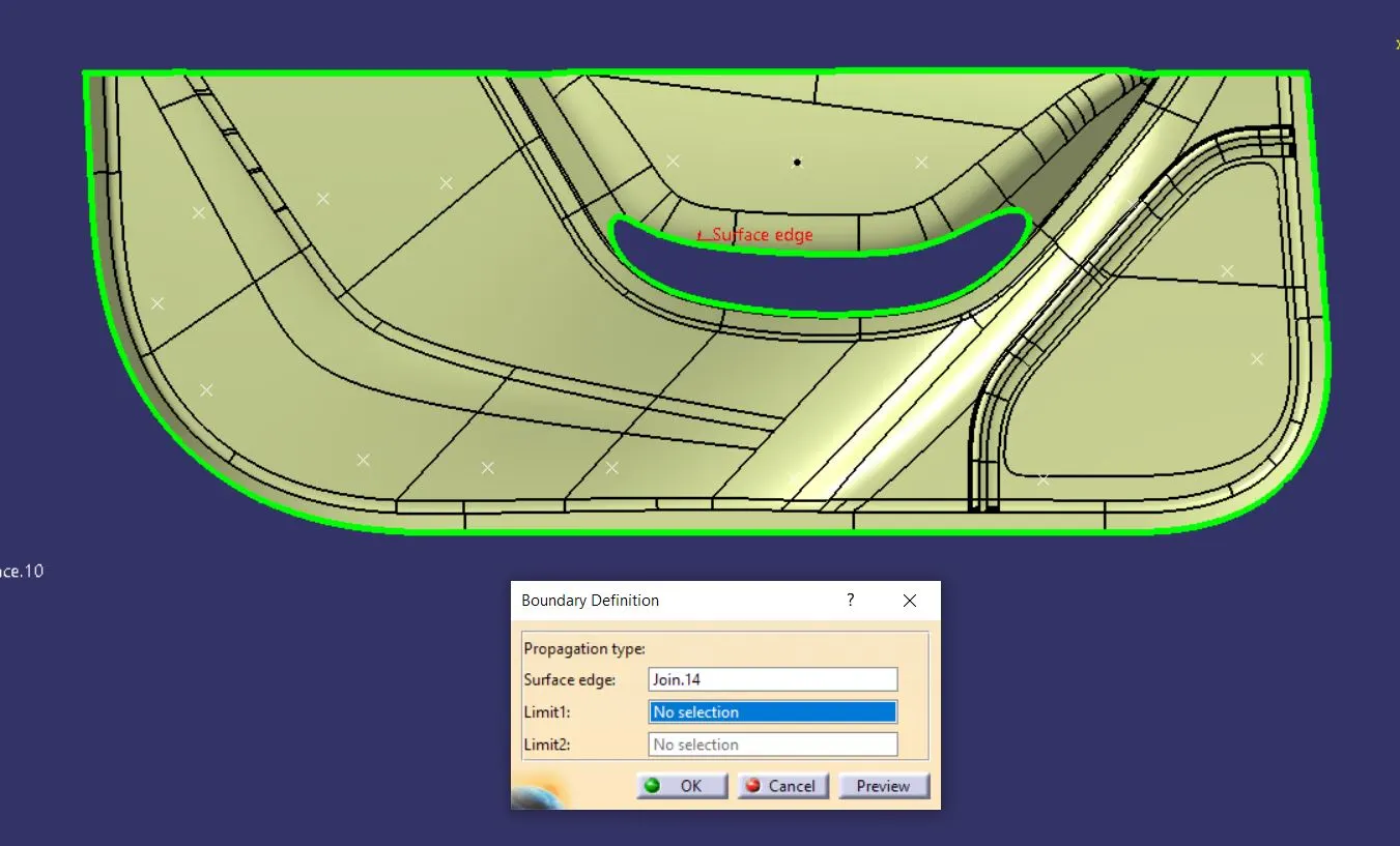
Creating Surface C
· Using Boundary & Sweep command, the Class C surface is created as shown below:
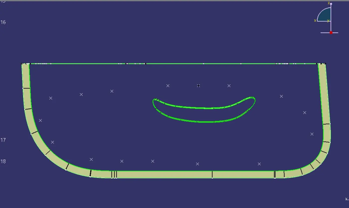
Final Tooling Surface
· Now using Trim command all the excess surfaces are trimmed and required final surface is formed as shown below:
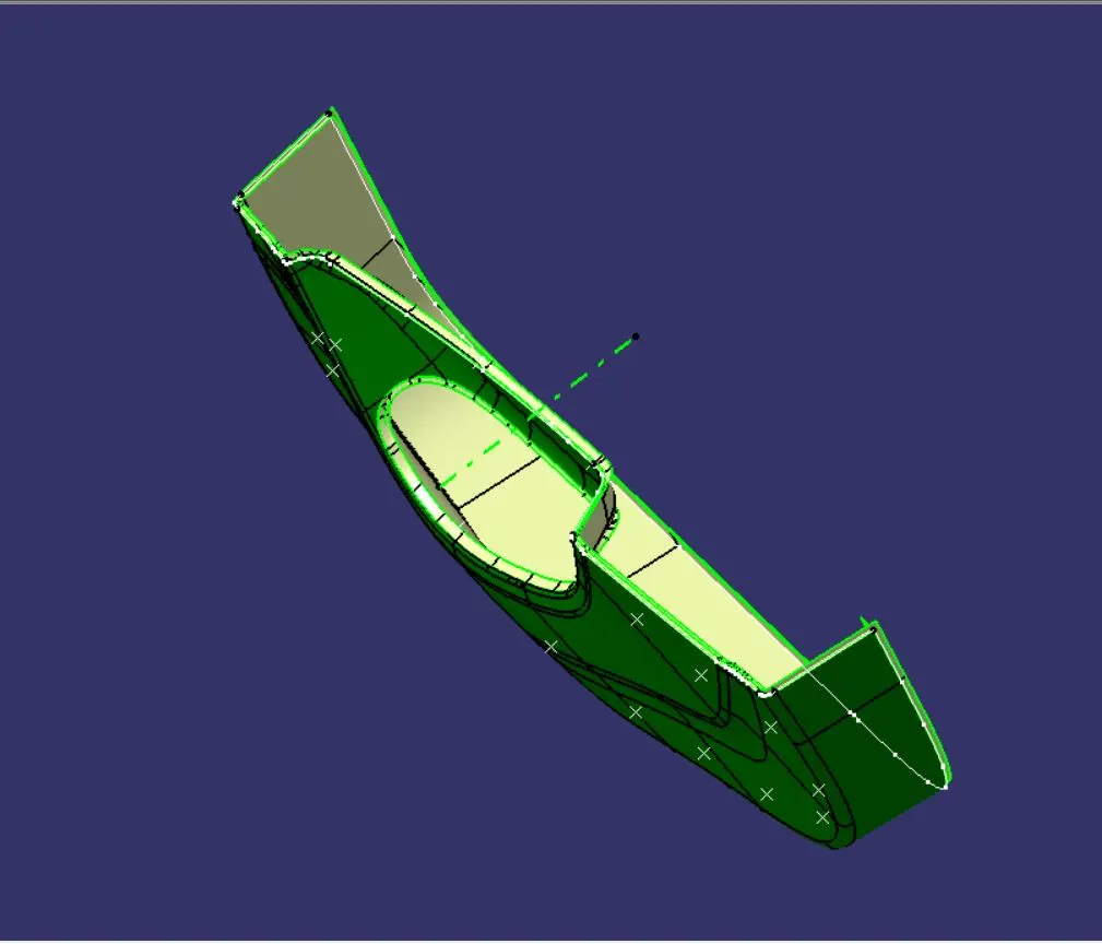
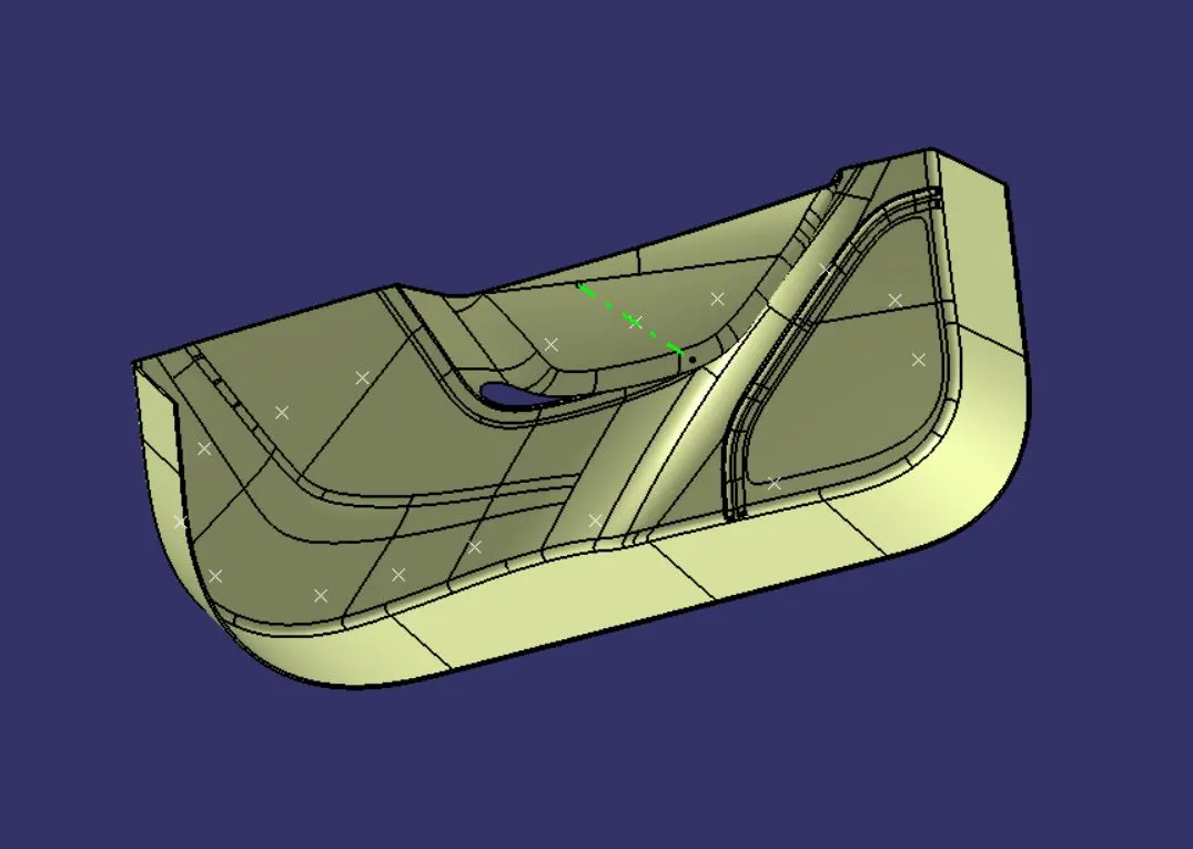
Draft Analysis on Final component
· As shown below the Draft angle is under well acceptable range for the Final part which is 3°.
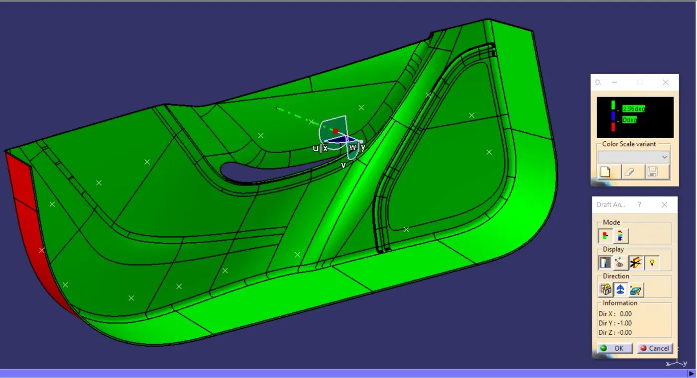
Converting to Solid Body
· After completing the Final surface, shift to Part Modelling interface, now using Closed Surface Command the whole Surface body is now converted into solid Plastic Component.
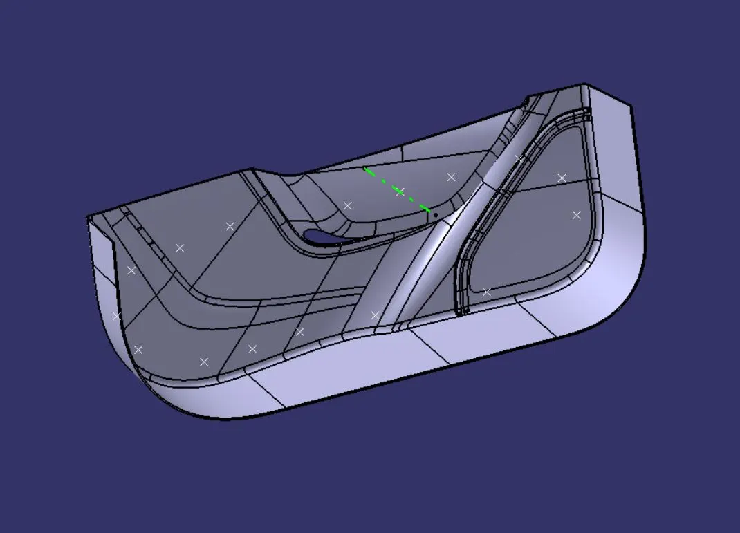
Heat Stakes & Locater Creation
· Now using part modelling the Heat Stakes is created using same Tooling Axis as reference.
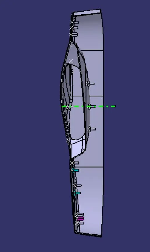
· Heat stakes are created on the provided points & locater are created asper provide image in the assignment.
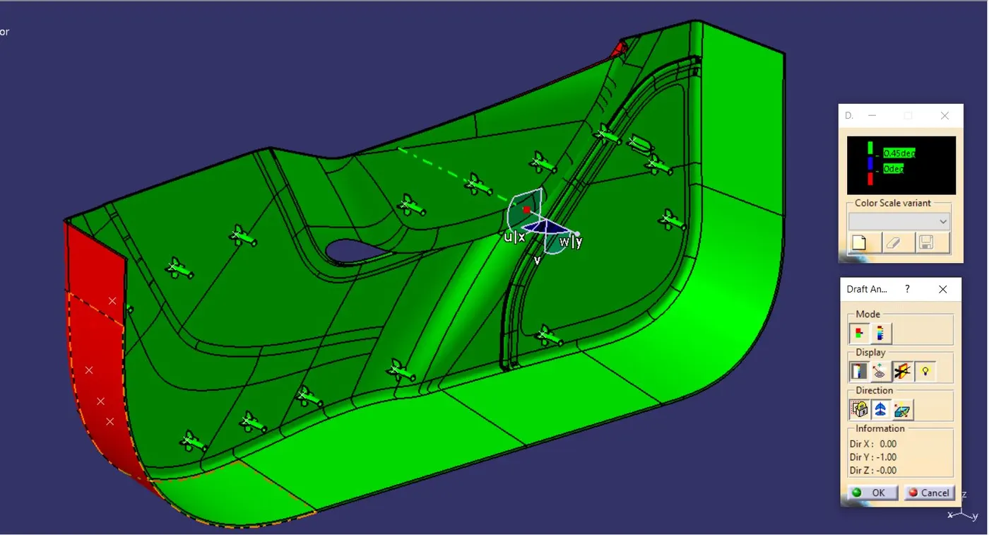
· From the below image it is clear that the draft analysis of the Heat Stakes & Locaters is well under acceptable range which is 0.45°.
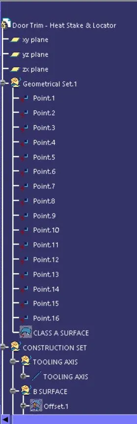
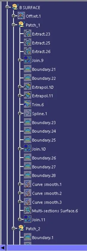
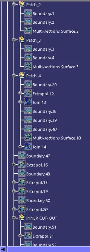
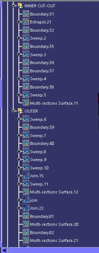
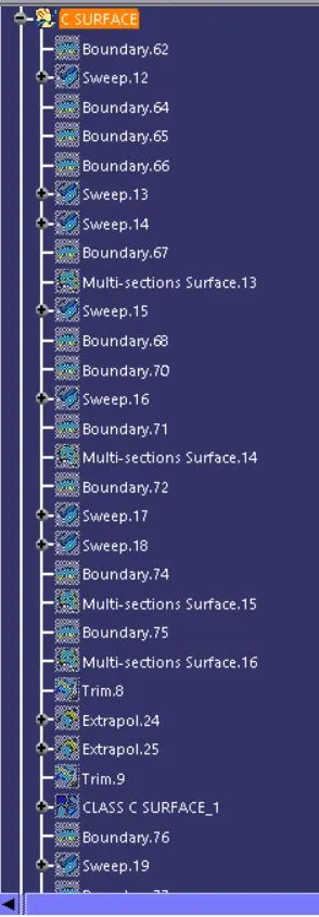
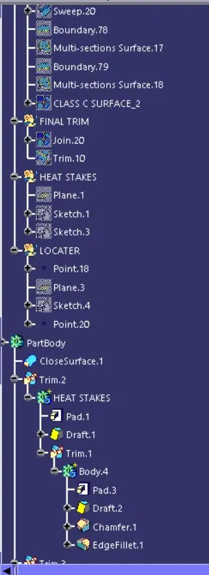
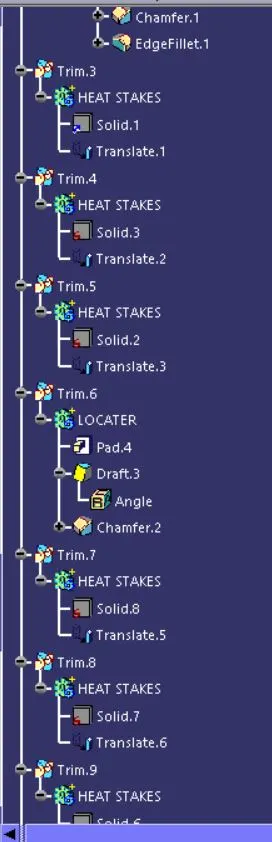
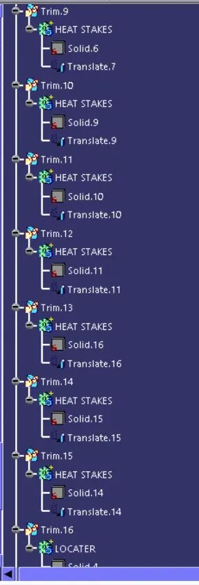
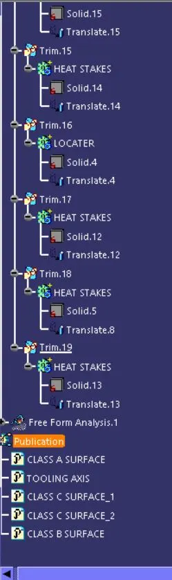
Following are the images of the Final Plastic Component & its Tree Structure :