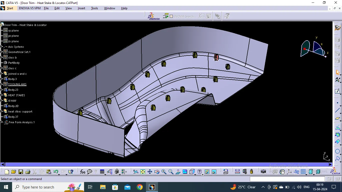
Week 10 - Challenge 3 - Door Trim Lower with Engineering Features
Given A Surface and points
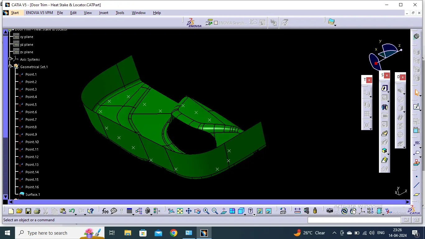
Tooling Axis Creation
To create tooling axis:
- The open boundary was extracted and then a bisecting line was created using that in between the non-parallel boundary lines.
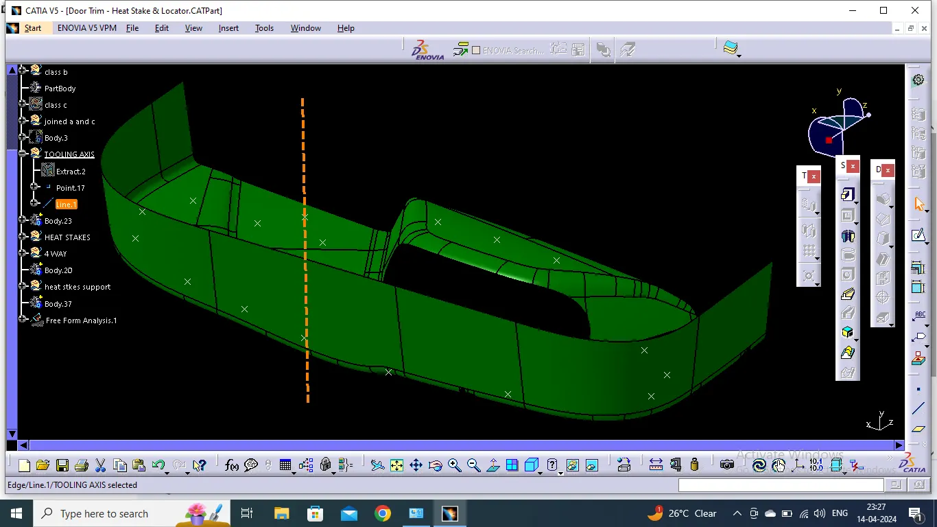
B -Surface Creation
To create a B-Surface :
- The A-surface was offested using offset surface command by 2.5 mm.
- Some patches were still there that was filled using splines, multiextract and multisurface command.
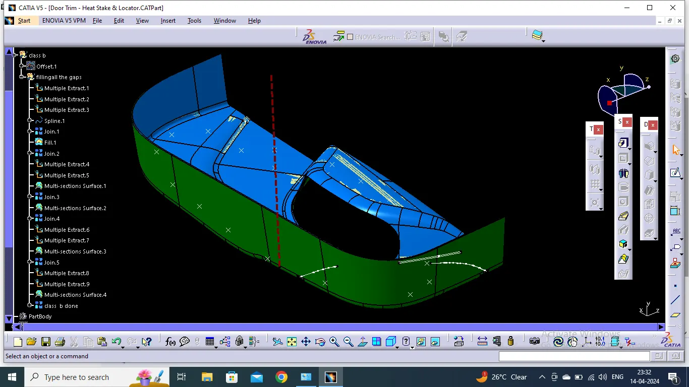
C- Surface creation
To create a C-surface:
- Using the boundary command we extarcted the boundary of A-surface .
- Two different profiles were extarcted during that process .
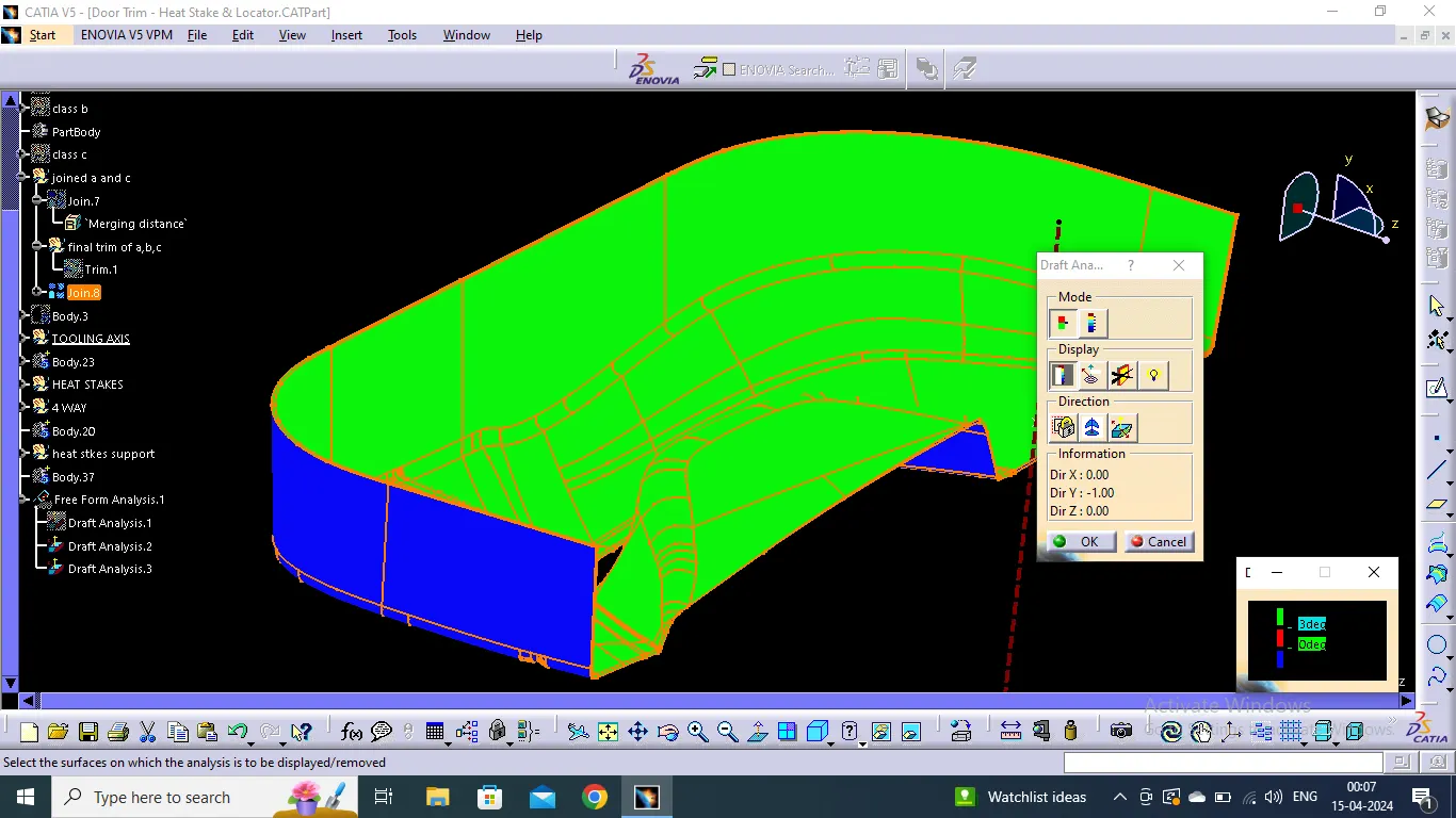
- Both the profiles were sweeped in tooling axis direction with some draft angle (3 degrees in our case) in either parallel or perpendicular direction whatever was required there.
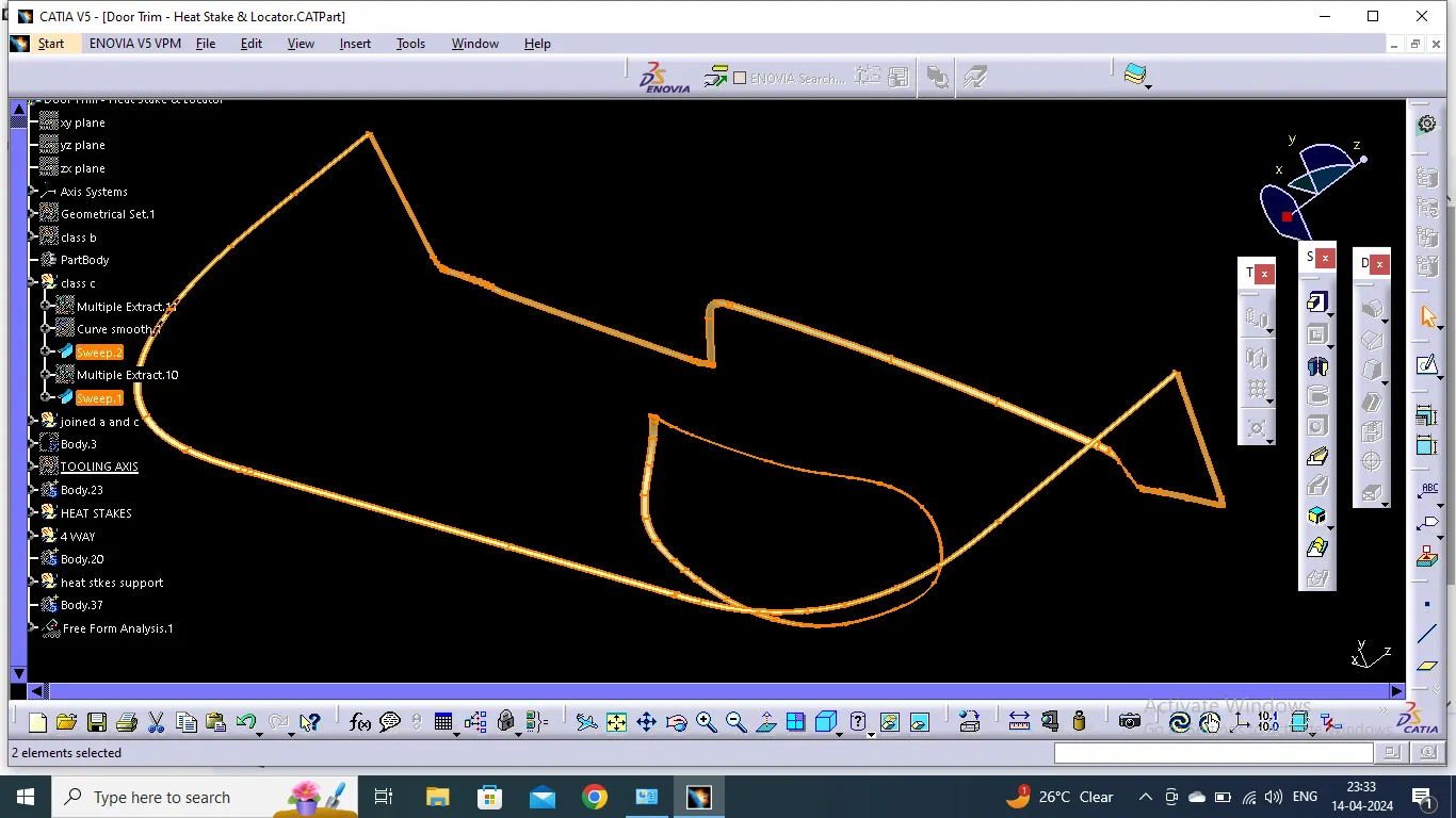
Creation of A -C Surface
- Joined the A and Surface using the join command.
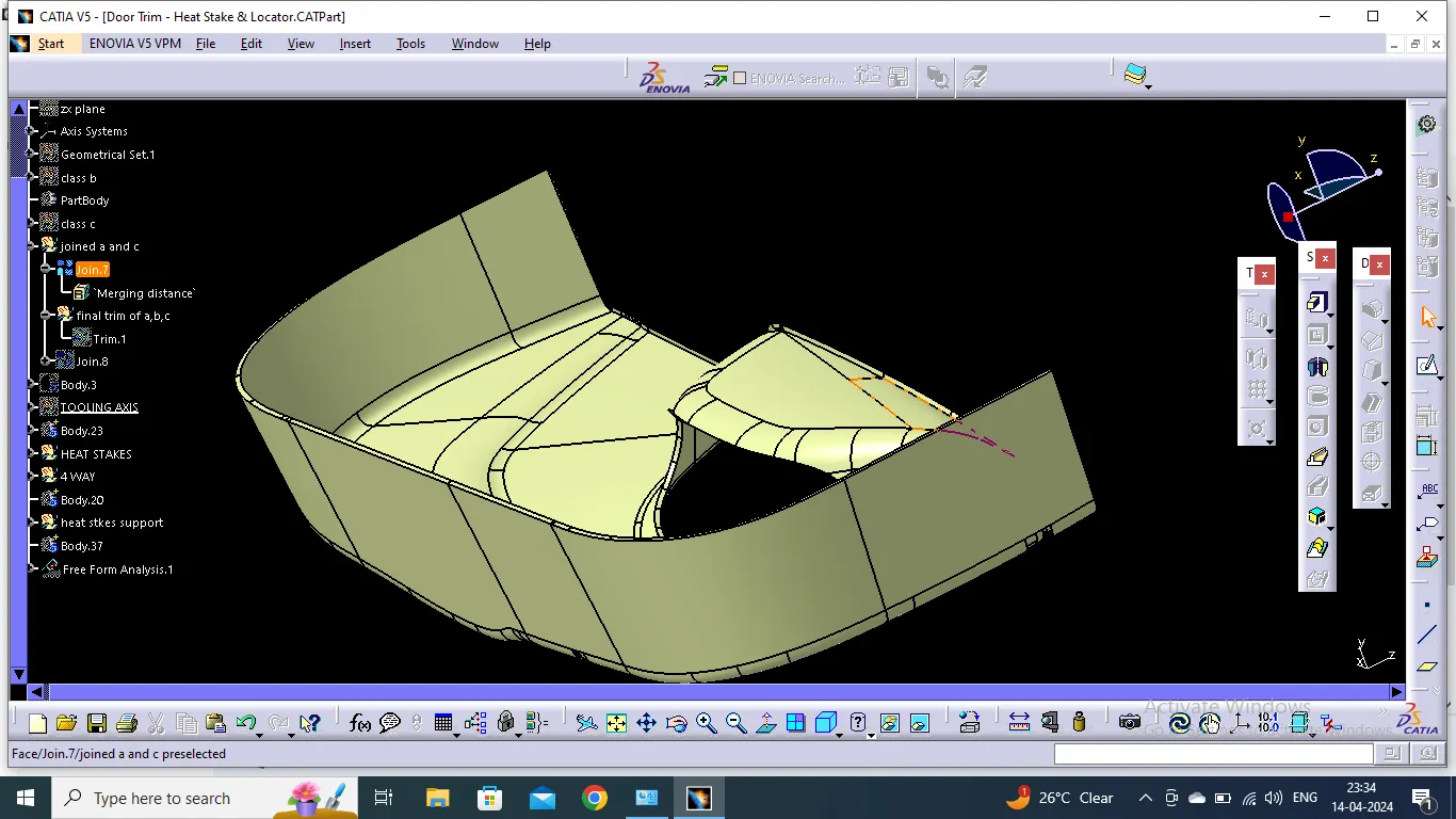
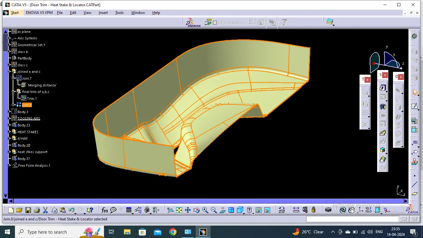
Creation of closed surface
- Closed Surface was created when we trimmed B-surface with A-C Surface.
Draft Analysis for closed surface
Draft Analysis was done on the closed surface as shown the results below:
The surface file woud then be converted to solid part file using close surface command in part modelling section.
Creation of Four way locaters
- Two four -way located have been created as per the given image reference in the task above.
- Those are placed in such a way to restrict multiple DOF for the door trim .
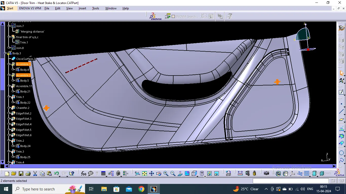
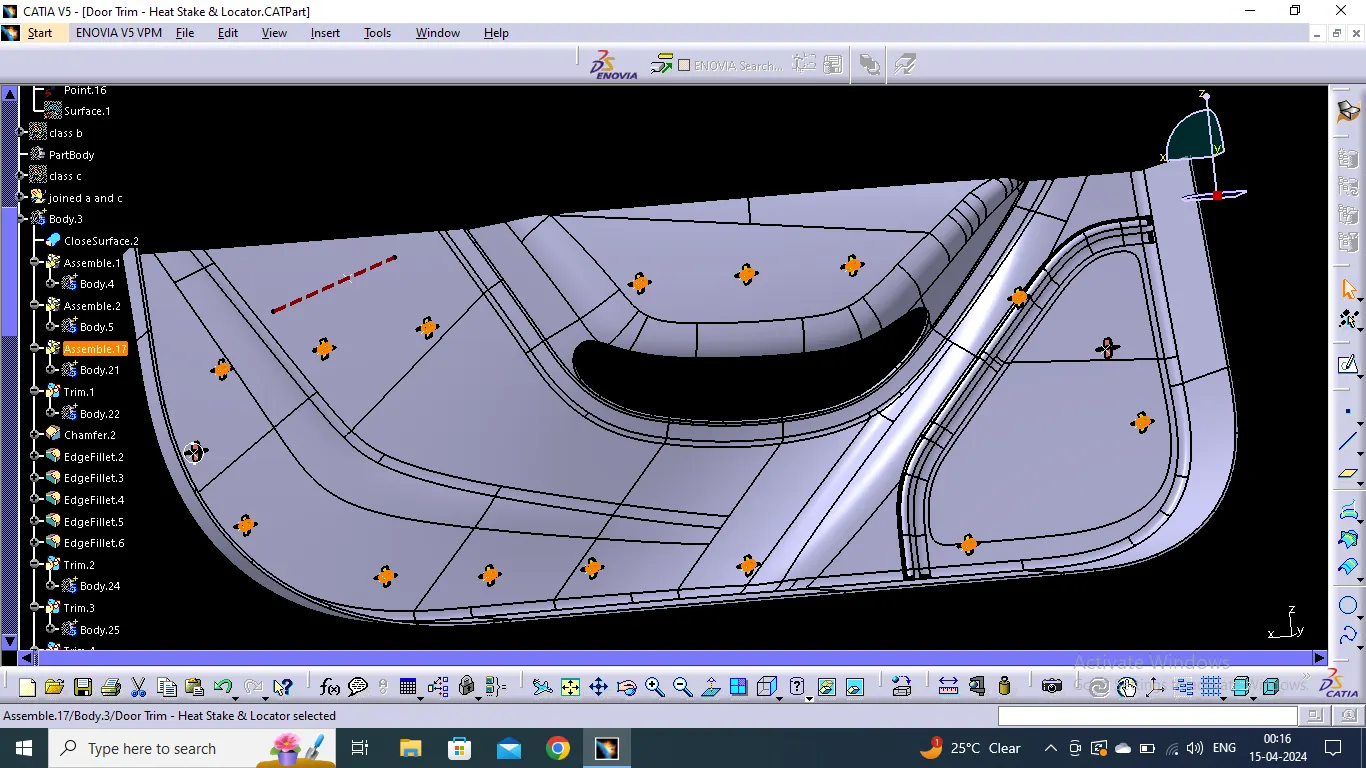
Creation of heat stakes
Heat Stakes were created using the points given in the task and according to the tutorial vidoes:
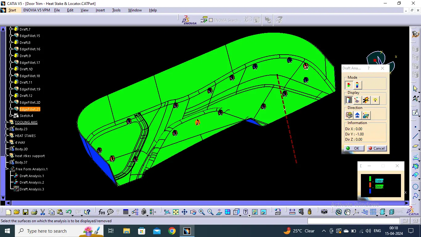
Draft Analysis for the completed part file
Draft Analysis was done on the completed part file as shown below:
Below down there is a completed part file , you can access the zip file attached down below with these screen shots.