Week 10 - Challenge 3 - Door Trim Lower with Engineering Features
DOOR TRIM WITH LOWER ENGINEERING FEATURES
AIM:
To create the door trim lower component through the given class-A surface.
OBJECTIVES:
- Creation of tooling axis with appropriate draft angle.
- Creation of other surfaces (Eg; B and C surfaces) for creating a solid component perform draft analysis for a class-A surface and solid model hence.
CREATING TOOLING AXIS:
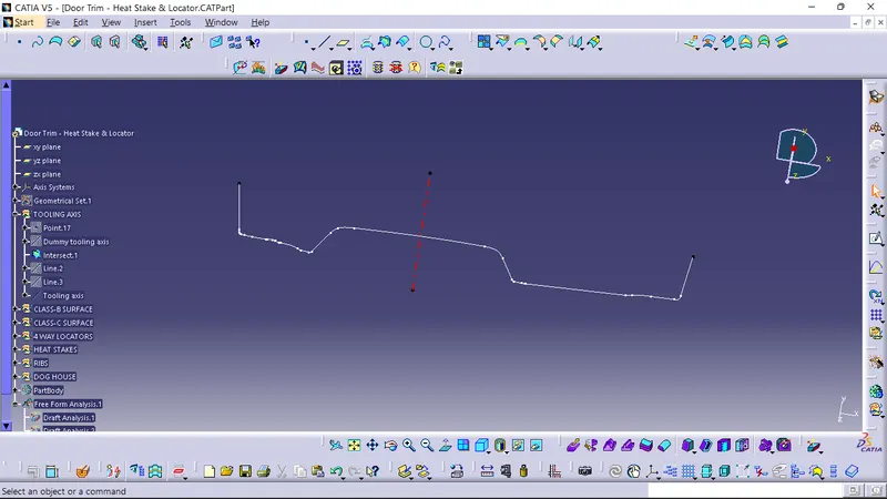
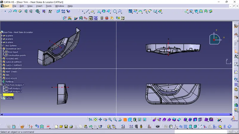
- To create the tooling axis, I extracted a surface from class-A and create a point in the middle of the surface.
- Created a line with the point at point through the X-axis.
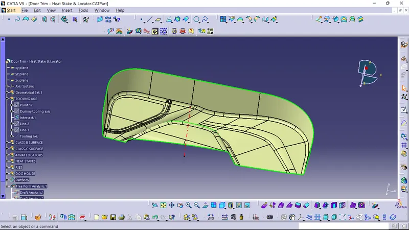
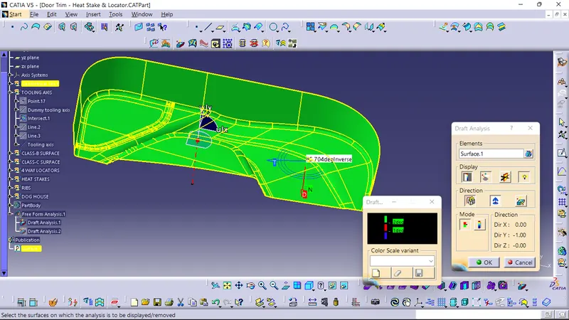
- Now I perform the draft analysis check from that line weather the created the tooling axis is in correct position or not.
- If in the draft analysis check the surface highlighted with green color both side of the surface.
- The surface of the tooling axis is in the correct position and direction.
DRAFT ANALYSIS FOR CLASS-A SURFACE:
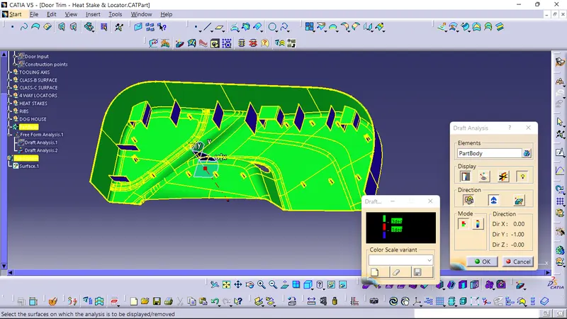
- We do perform the draft analysis to check the class-A surface before we make solid and B-side features.
- Initially I align the compass to the tooling axis and i have a 3 deg draft angle for the green color in the color bar.
- If the surface heighlight in green color the draft angle is given properly for class-A surface.
- If the class-A surface not heighlighted in fully green color, that might be reason for the draft angle of the class-A surface.
Class-B SURFACE CREATION:
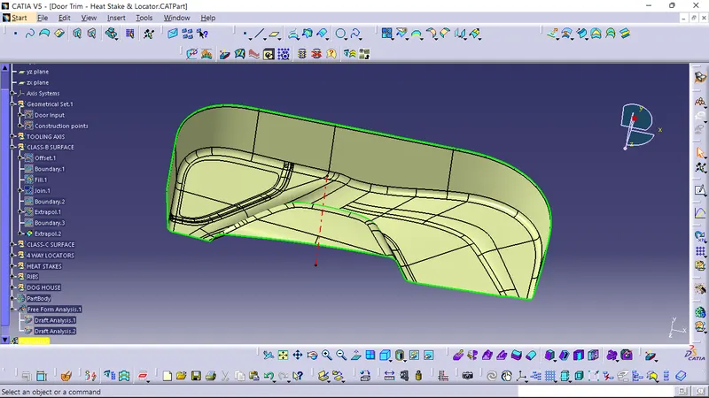
- To create the class-B surface offset the class-A surface inside us per our thickness requirement.
- Ones the offset is created, we can observe some patches on the offset surface by taking the boundary for the offset surface.
- Those patches are formed due to the fillet on the class-A surface.
- We need to cover those patches with the help of multi section surface command by extracting the patch boundary.
- Ones all the patches in the offset are covered properly join all the patches with the offset surface, to get the replicated surface of class-A.
CLASS-C SURFACE CREATION:
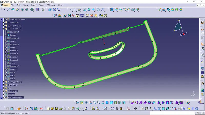
- I use sweep command to create the class-C surface concerning the boundary of the class-A surface.
- Initially I extracte the boundary of class-A surface with tangent continuty, and I sweep the extrated boundary.
- Ones we sweep all the surface boundaries of class-Aclass-A, extrapolate the sweep surface until both surface get interest properly.
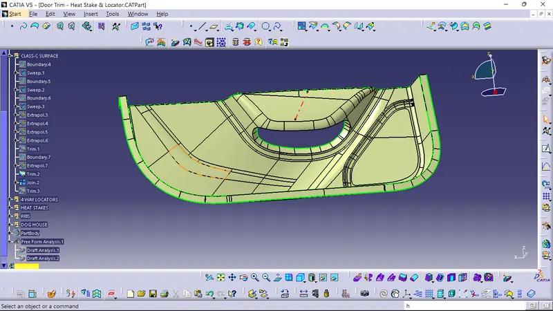
- And trim them to remove extended extrapolate surface to get a proper sweep boundary through out the entire surfaces.
- Including the center hole of the door trim.
- Now join both class-A and sweep boundary to get complete class-C surface.
PART BODY:
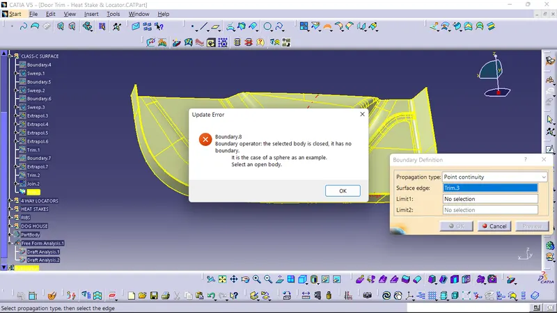
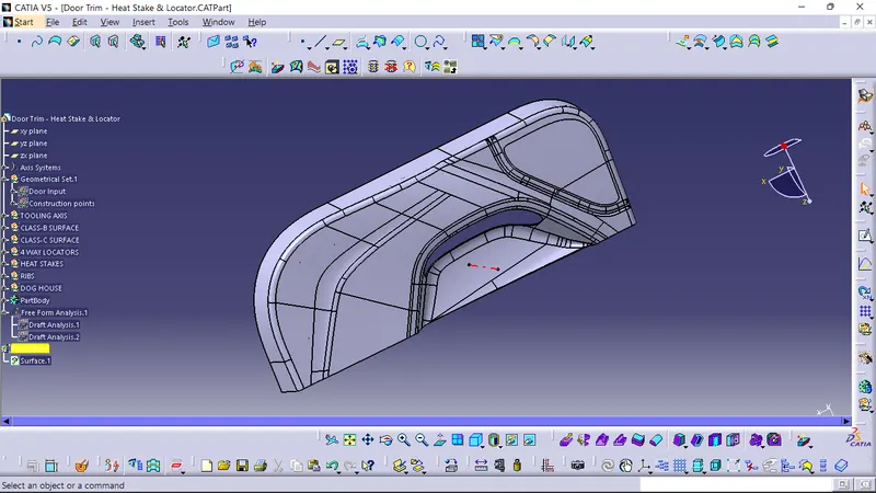
To create the solid part body from the closed surface, I used the close surface command In the part workbench.
CREATION OF LOCATORS:
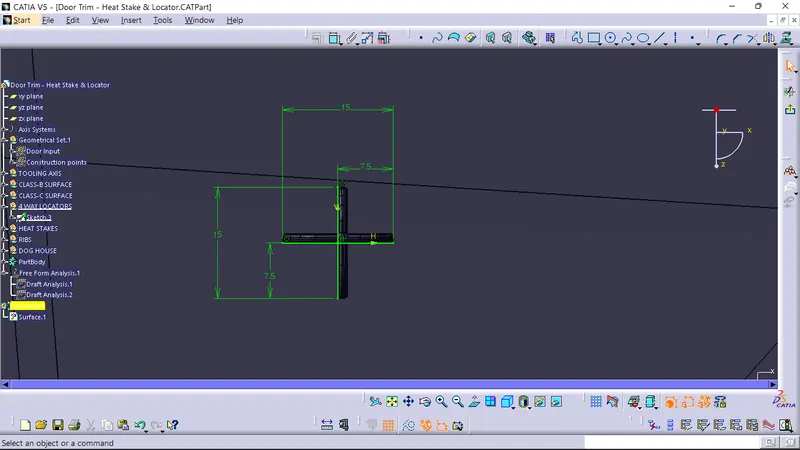
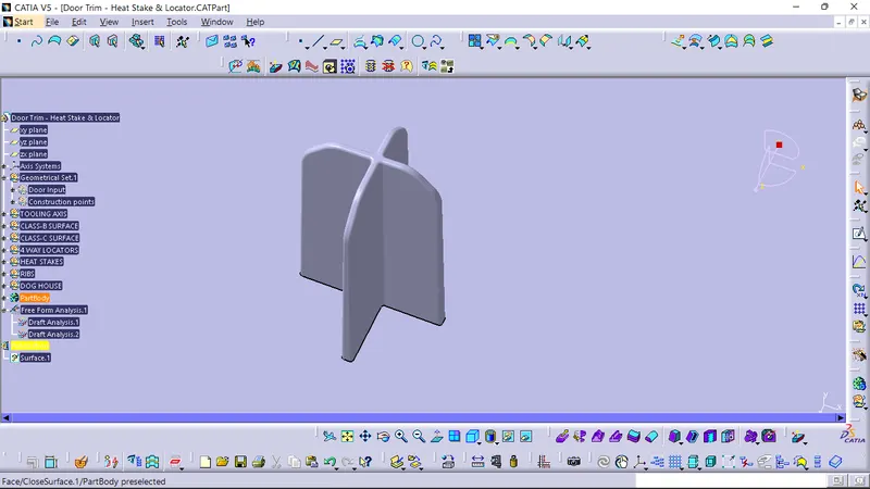
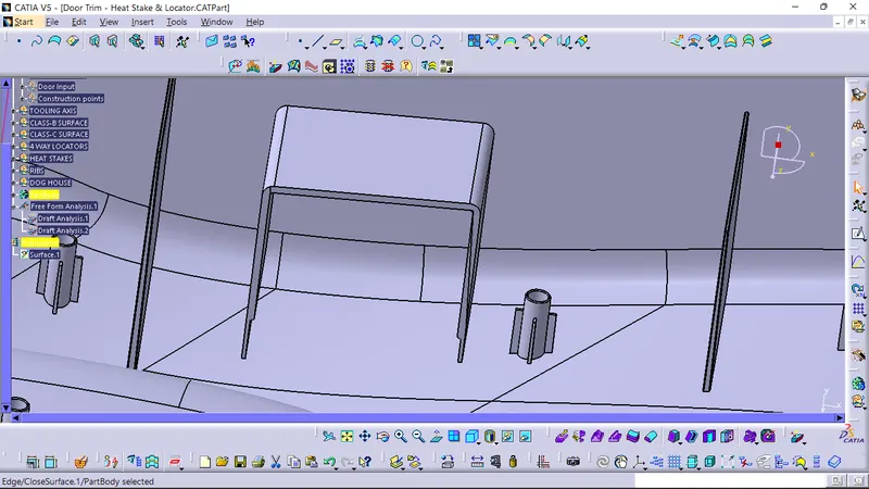
To create the locators, i created a sketch on the body. After creating the sketch i pad it and thicken it to 1.3mm and drafted it with 0.5deg in the direction of the tooling axis. I have 3mm champer with 45deg of inclination and after I have a fillet of 0.25mm radius.
CREATION OF HEAT STAKES:
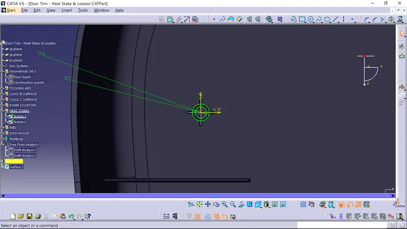
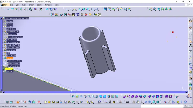
To create the heat stakes, I draw a sketch on the surface. After creating sketch, I pad it and i have a draft angle of 0.5deg on both sides (inside and outside) and I have fillet with 0.25mm radius. After creating the heat stakes, i created the ribs for the supporting purpose.
CREATION OF RIBS:
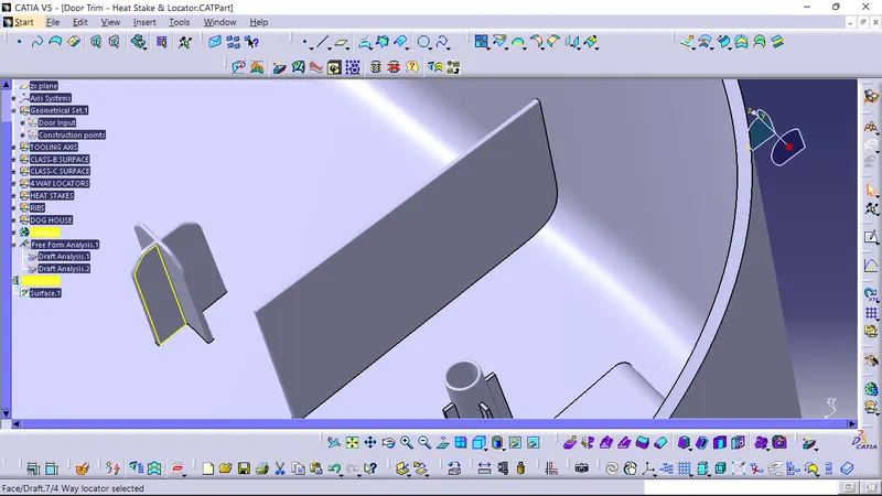
Ribs are feature in plastic injection molded parts, they are thin extension that run perpendicular from a wall or plane. They are commonly used to provide additional support and strength to a part. Thickness and locations are essential to ribs design.
To create a ribs I draw the sketch and pad it and give 1mm thickness. After drat 0.5deg in the tooling axis direction and fillet with 0.25mm radius.
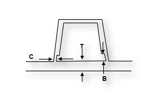
CREATION OF DOG HOUSE:
- To create the dog house i draw a sketch and pad it.
- After pading in the direction of tooling axis, I drafted in 3deg of tooling direction and fillet with 3mm radius.
- Then I removed the material from the base it having a thickness of 0.4*T=1mm.
- Then provide drat it to 0.5deg to the direction of side core axis.
- Then shell the main padded structure to 0.7*T=1.75mm
- Remove the second body from the first body.
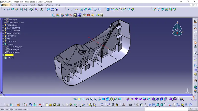
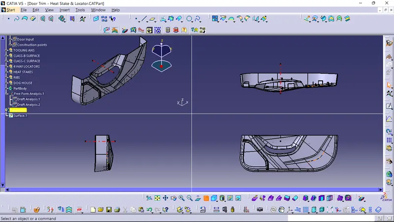
- After producing all the dog house Untrim with the solid part body. The final produced solid body having all the features show blow.
DRAFT ANALYSIS FOR PART BODY:
FINAL COMPONENT: