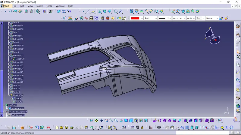
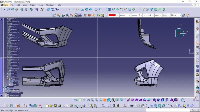
Week 9 - Challenge 3 - Bumper
BUMPER DESIGN
AIM:
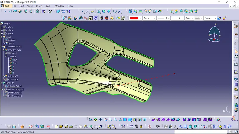
Create the bumper plastic component through the given class-A surface. To begin with, the tooling axis for the given class-A surface should be created meeting the requirements of the draft angle and at the end perform the draft analysis on the model.
INTRODUCTION:
A bumper is a structure attached to or integrated with the front and rear ends of a motor vehicle, to absorb impact in a minor collision, ideally minimizing repair costs.
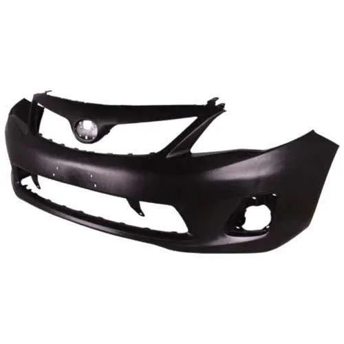
They are designed to absorb impact to the front and rear of vehicles and minimize lpw speed collision damage. Today standard passengers vehicles bumper have a rigid reinforcing bar under the outer cover, with section of Compreasible foam or plastic underneath.
A bumper is made of four parts;
- Bumper cover
- The bumper absorber
- The bumper reinforcement bar
- The bumper mounting system.
Bumpers of most modern automobiles have been made of a combination of Polycorbonat (PC) and acrylonitrile butadiene styrene(ABS) called PC/ABS.
OBJECTIVE:
- To design bumper as per automotive industry standard.
- Create tooling axis for the given class-A surface.
- Create class-B and class-C surfaces.
- Create final surface model and convert it into solid body using close surface command in the part design work bench.
- Perform draft analysis for both class-A surface and final part body.
CREATING THE TOOLING AXIS:
Tooling axis represents the opening and closing of the mould core and cavity during the manufacturing of the components. A plastic product designer should consider the best tooling direction to cut down the cost of the component very less.
- Check the best tooling direction for the given surface.
- We can find out the best tooling direction by cross checking all the three axis.
- Here we can find out the best tooling direction for the bumper class-A surface is along X-axis direction.
- The method I choose to create the tooling axis is first extracted a surface and create a midpoint on that surface. The introduced an axis system on that point.
- Then created the line with the point and direction along with the X-axis.
- Another method is by creating intersection along Y direction and then create lines on walls and then create a bisecting line with the lines on the wall and point created earlier. We will get an axis which will satisfy the draft analysis direction.
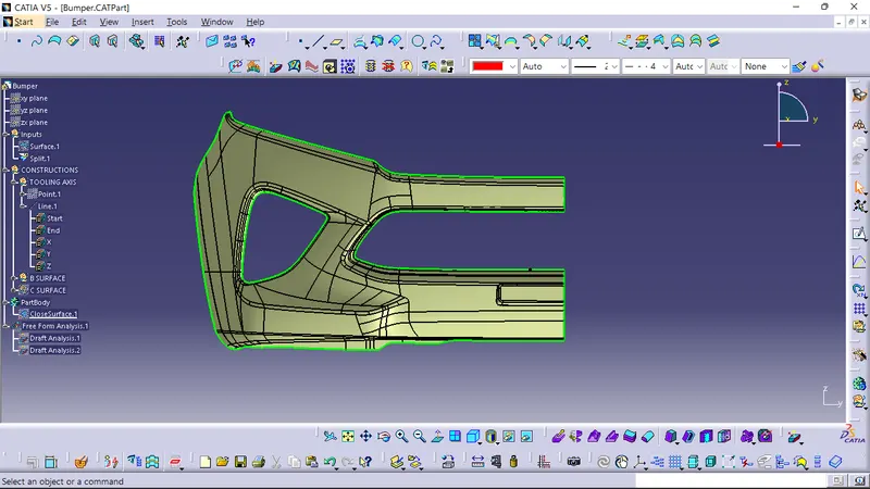
DRAFT ANALYSIS FOR THE GIVEN CLASS-A SURFACE:
- Procedure for performing the draft analysis are us follows.
- Change the view mood of the component to be in customized parameter mood and then select the shading mood as material.
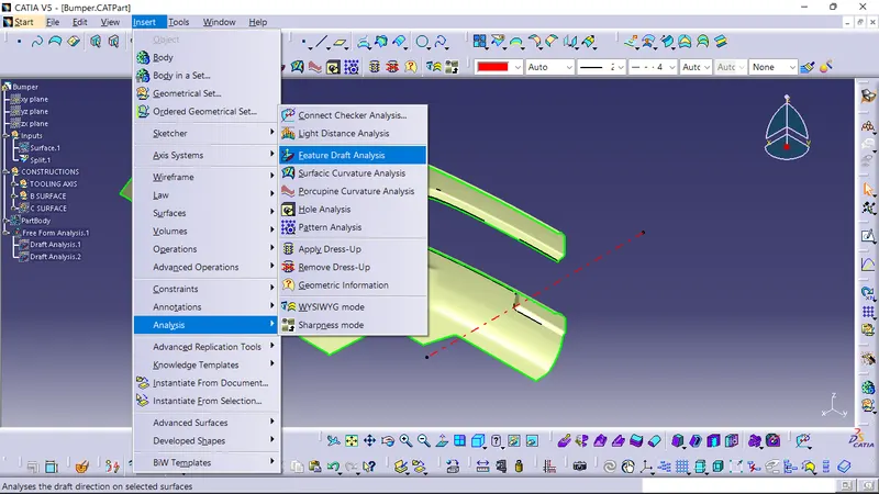
- Then open the feature draft analysis tool from the insert menu.
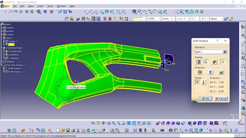
- Then click on use the compass to define the current drafting direction and then drag and align the compass on the tooling axis.
- Then lock the draft direction and perform draft analysis by clicking on the component.
- The green color shows the positive draft tooling direction and the given surface passes the draft analysis.
- Click on the analysis under the running point to check the draft analysis on the individual faces. It shows how much draft on specific point when we move the cursor point.
CLASS-B SURFACE CREATION:
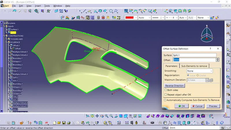
- Ofset the class-A surface to 3mm inward directiondirection.
- Rework on the patches and discontinuity of the ofset surface using the features like extract, multiple-extract, extrapolate, trim and join.
- To ensure the continuity of the class-B surface check the boundary command to find out the boundary.
- Hence class-B surface creation is done.
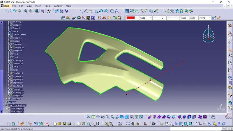
CLASS-C SURFACE CREATION:
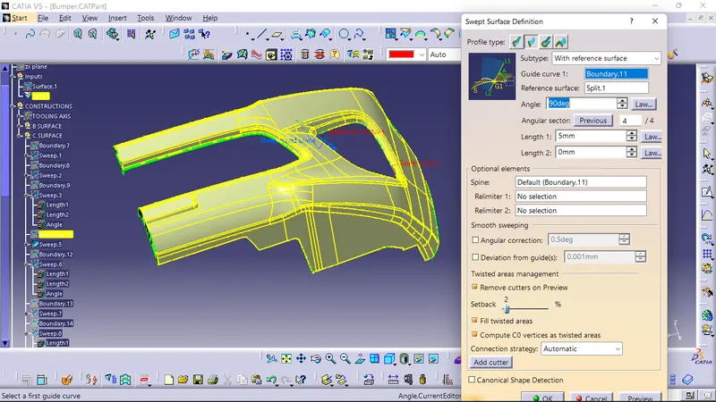
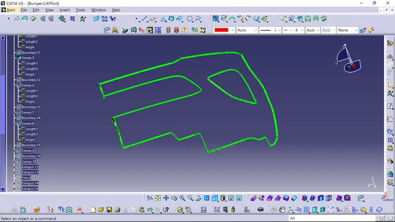
- Since it is a complex class-A surface, we cannot simply create the class-A boundary curve and sweep it at one shot.
- Hence, we need to create smaller curves using multi extract command and then create sweep.
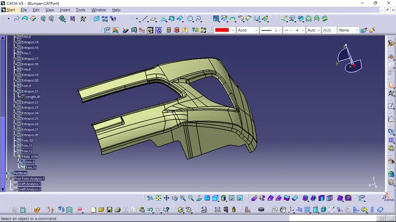
- Extrapolate and trim of the sweep surface corners at the required edges.
- Join the sweeps using the join command and the class-C surface is created.
FINAL PLASTIC COMPONENT: