Week 10 - Challenge 1- Attachment Feature Creation (Ribs & Screw Boss)
ATTACHMENT FEATURE CREATION (RIBS & SCREW BOSS)
Aim:
- To create the door handle component from the given class-A surface.
- To create the tooling axis for the given class-A surface meeting the requirements of the draft angle.
- To attach B side features (Ribs & Screw boss) in the component.
- To perform the draft analysis on the model.
TOOLS USED:
- Boundary
- Join
- Multiple extract
- Bisecting line
- Trim
- Offset
- Draft analysis
- Sweep
- Close body surface.
DESCRIPTION:
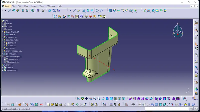
CREATING TOOLING AXIS:
- Open the given CAT Part file.
- Check for gap between the surfaces for that click on join and them preview.
- If there is any gap between the surfaces join them with a maximum tolerance of 0.003mm.
- Extract the boundary and disassemble the boundary.
- Find the correct tooling axis where the material don't interfere with the tooling axis and all the elements can be created.
- Create an axis system using at the center of the door handle.
- Intersect the YZ plane with respect to the class-A surface.
- Hide the class-A surface and create the point to point lines on the suspected draft.
- Create bisecting line to the two lines and point to create the tooling axis.
- The tooling axis is created for the component by using bisecting line.
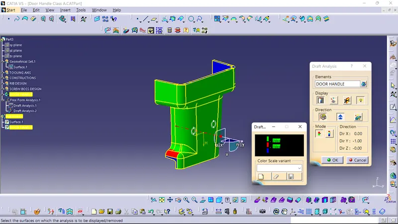
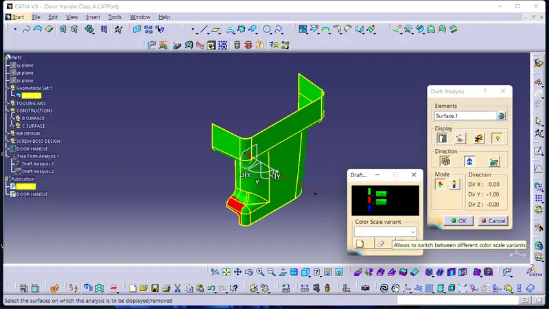
CLASS-A DRAFT ANALYSIS:
- Before going to draft analysis go to customized view parameter~under mesh~check material and then click ok.
- Now for draft analysis go to insert~analysis~feature draft analysis.
- Use the compose to define the draft direction.
- In the colour scale change to the draft angle 3 degree.
- The component changes into green color indication of passing the draft angle.
- Use running point to check the angle of the component.
- The draft analysis is complete.
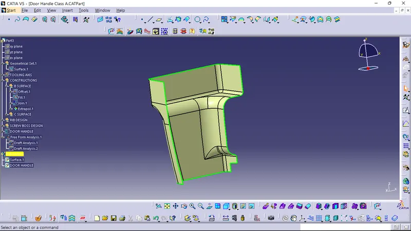
CREATING ClASS-B SURFACE:
- Extract the surface from the class-A using multiple extract and untrim them.
- Use extrapolate to make sure that all the untrim are properly intersected to the trim.
- Offset the surface to 2.5mm to create the thickness.
- Trim the extract surfaces using trim command.
- Apply fillets to the model after creating the entire surfaces.
- Extrapolate all edge to the surface 5mm so can avoid the gap.
- Verify the B surface no gap marks in the surface.
CREATING CLASS-C SURFACE:
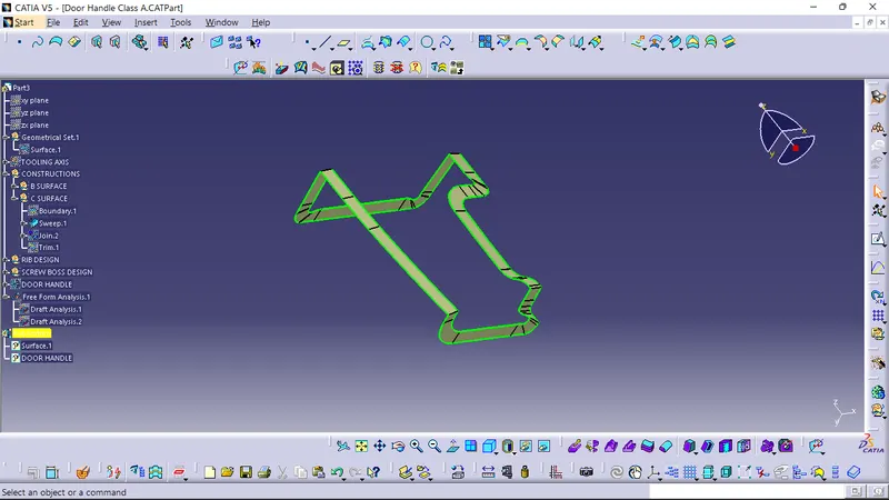
- Extract the boundary from the class-A surface using boundary command.
- Use disassemble tool to devide the boundary as the boundary contains domain.
- Use sweep command~surface with draft direction~choose guide curve and draft direction~give draft angle~preview.
- After getting sweep and then trim the output with class-B surface to get final output.
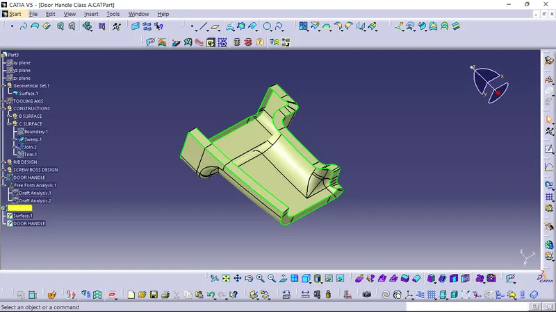
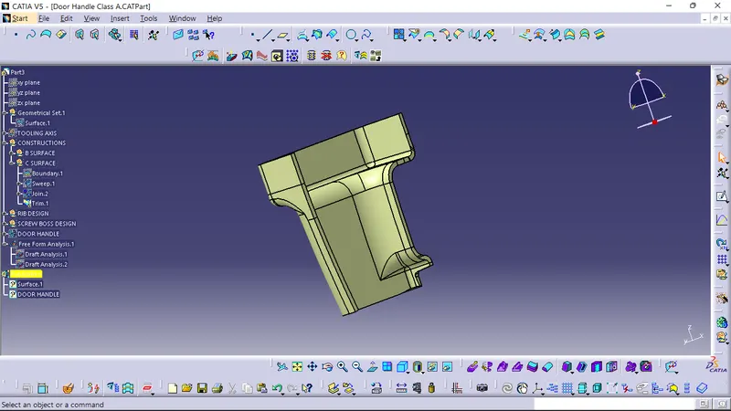
FINAL COMPONENT:
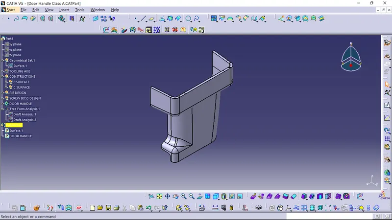
RIB CREATION:
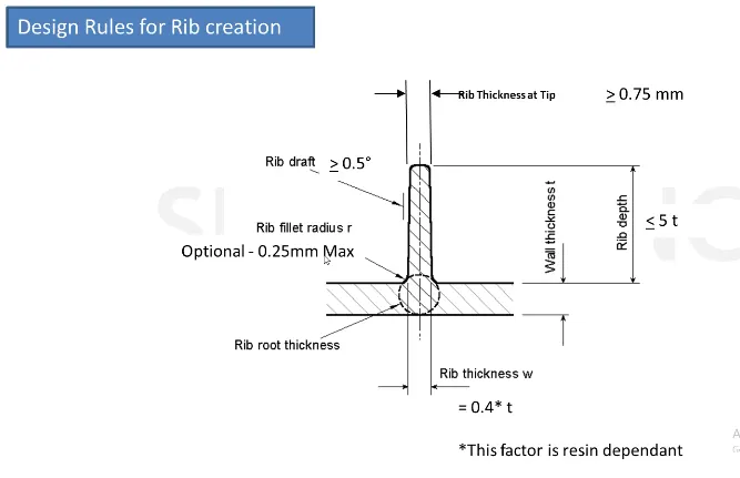
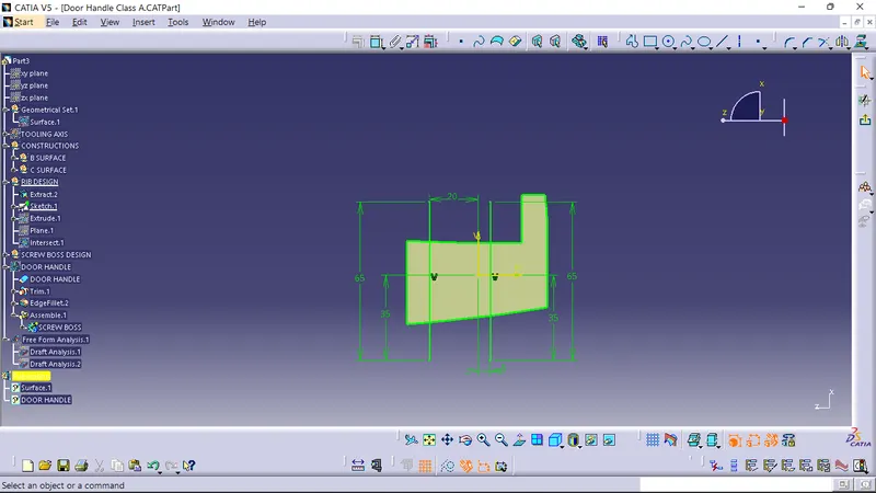
To create rib feature in model select the line and draw where you want it. Extrude the line surface height 3 times to the thickness.
Thick the surface and later draft 0.5° all sides. Finally give edge fillet 0.25mm.
- DESIGN PRINCIPLE FOR RIB CREATION:
SKETCH USED FOR RIB CREATION:
SCREW BOSS CREATION:
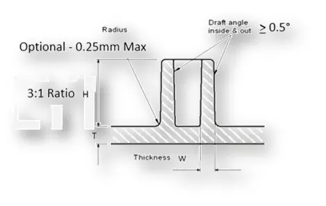
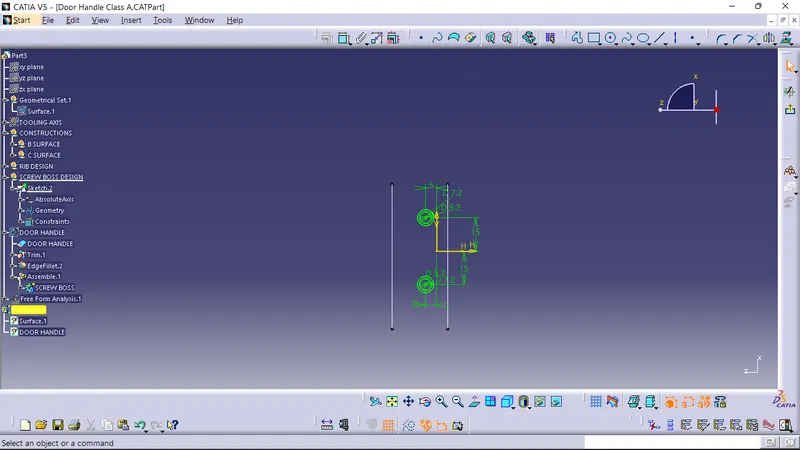
To create a screw boss wall thickness must be 1.5mm Of screw hole diameter. Height 5 times of wall thickness and draft angle 0.5° at outer edge fillet 0.25mm add the body to the main body.
- DESIGN PRINCIPLE FOR SCREW BOSS CREATION:
SKETCH USED FOR SCREW BOSS CREATION:
FINAL COMPONENT:
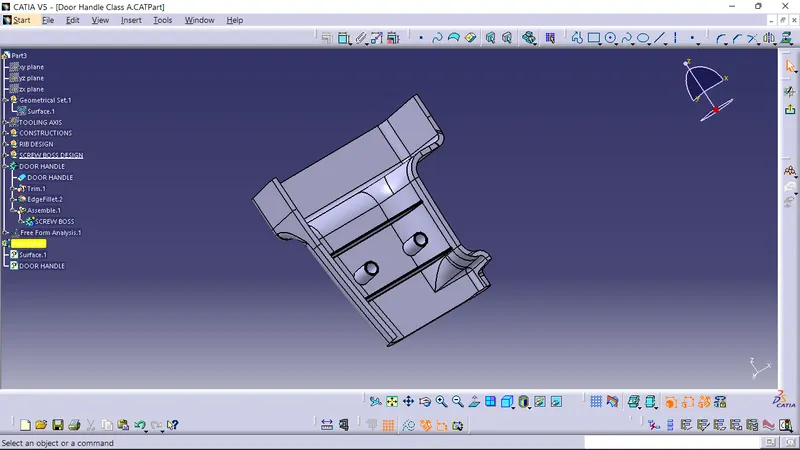
FINAL COMPONENT DRAFT ANALYSIS: