Week 9 - Challenge 2 - Switch Bezel Design
SWITCH BEZEL DESIGN
AIM:
The project aims to create a switch bezel plastic component using the given class-A surface and perform the draft analysis.
OBJECTIVE:
- Ensure proper tree structure.
- Geometrical sets should have a proper name based on the sketches present inside them.
- All the sketches should be created under the geometrical set.
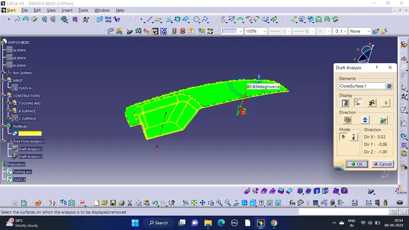
- Use the close surface feature to make a solid body from the surface.
- To publish the tooling axis, class-A, B and C surface.
INTRODUCTION:
CLASS A SURFACE: The class-A surface is used in the automotive design industry. It describe the final production surface data for the aesthetic parts.
CLASS-B SURFACE: The class-B surface is the second surface that has a surtain thickness from a class-A surface. This surface contains engineering aspects of a model. These must be smooth and "error free" as well but not held to the standards that class-A surface are.
CLASS-C SURFACE: The class-C finish alows more imperfection than class-A or B. Class-C is often specified for interior surface not readily visible, surfaces that will be covered by another part when assembled or surfaces
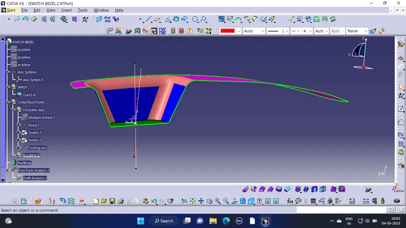
. CREATING TOOLING AXIS:
- The ejection from the mould after manufacturing the interior trim must have the nominal 3-degree draft angle.
- Hence the tooling direction created by considering the above factor And bisecting method is used.
- The bass surface of the class-A was extracted to create a reference point on the surface using the point, create the line in the Z-direction and an axis system was inserted to the point.
- Then using projection intersection along the yz plane is created and the two inclined lines were drawn inside the position sketch.
- Then bisecting lines with the two inclined lines were created.
- Now the same procedure is done along the zx plane but on zx plane, we only have one surface line so the center point is used to extrude a line alone the Z-direction and gave the measurement of 4 degree from the surface line
- Bisecting the sketche1 and sketch 2 the bisecting line created and published as a tooling axis.
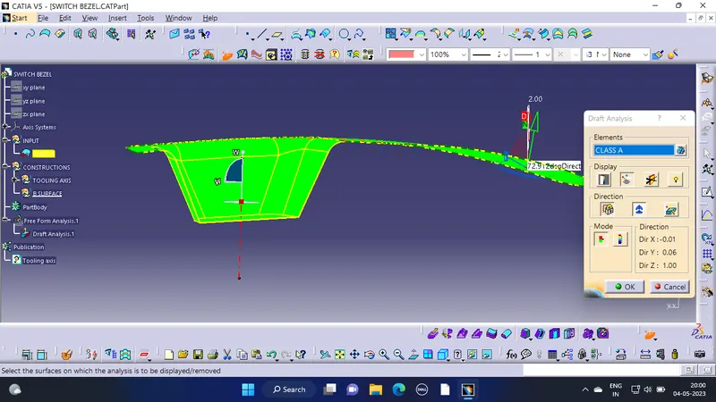
DRAFT ANALYSIS ON CLASS-A SURFACE:
- Go to insert>analysis>future draft analysis.
- Align the tooling axis with the compass.
- Click on the surface and see that the surface within the permissible limits of the draft value.
- The surface should be green and in the column nominal value at 3 degree given as input. Hence the draft analysis on the class-A surface is successfully performed.
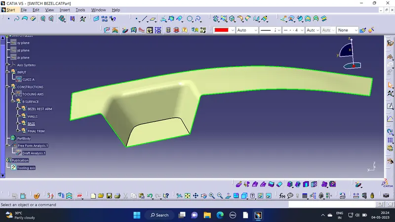
CLASS-B SURFACE CREATION:
- Divide the class-A surface into 3 different surfaces as 1.bezel rest surface 2.side walls 3.base.
- The first step is to extract the surfaces untrim and extrapolate the surfaces.
- Ofset the surfaces here the input is given as 2.5mm.
- Ones all the surfaces are created the required trim operation were performed to form a class-B surface.
- To perform the fillet operation. Fillet value should be calculated from the class-A surface for every edge in the B surface.
- The fillet value should be calculated to ensure the component has a uniform thickness.
CLASS-C SURFACE CREATION:
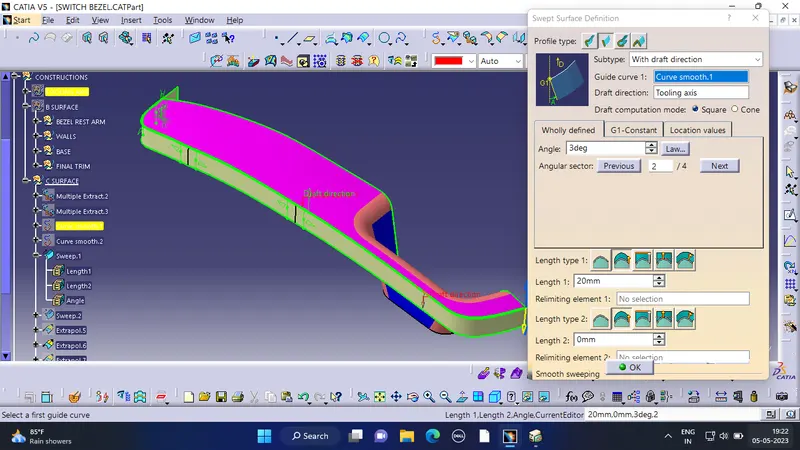
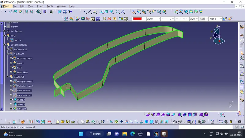
- The edges of the class-A surfaces are extracted using the multiple extract and then converted into smooth curvature to avoid the patches.
- Sweep operation is performed, selecting the smooth curves as the guide curve and the tooling axis as the direction and draft angle as 3 degree.
- Join class-A and class-C surfaces. Make sure that there is no unnecessary boundary present. It there is then increase the merging distance do not more than 0.003mm.
- Then trim the class-C surface with the class-B surface.
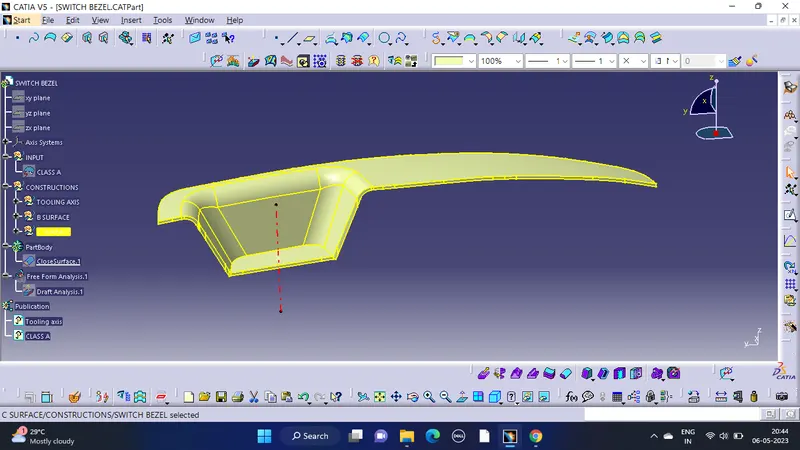
Go to part workbench by using the close surface feature we created a solid body from the surface.
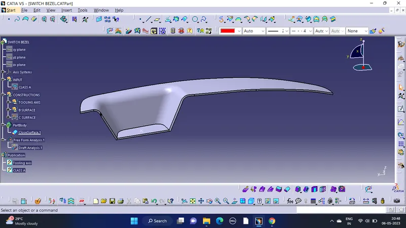
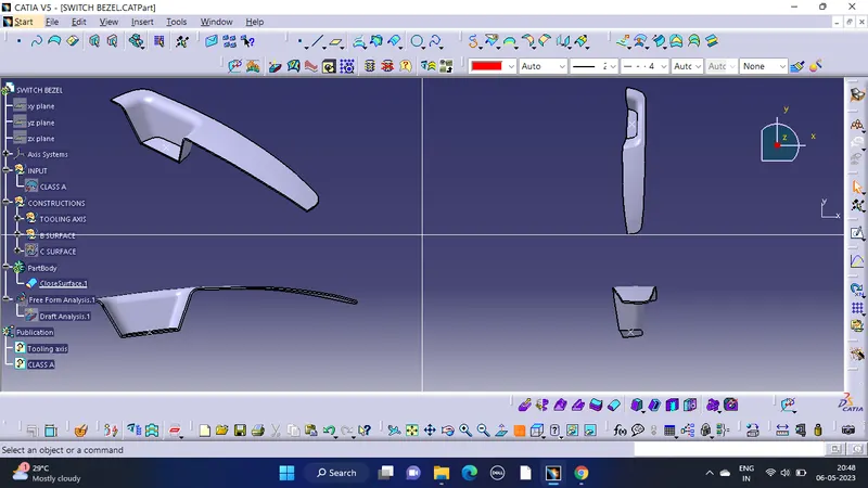
FINAL PART DRAFT ANALYSIS;