Week 10 - Challenge 3 - Door Trim Lower with Engineering Features
Challenge: Door Trim Lower with Engineering Features
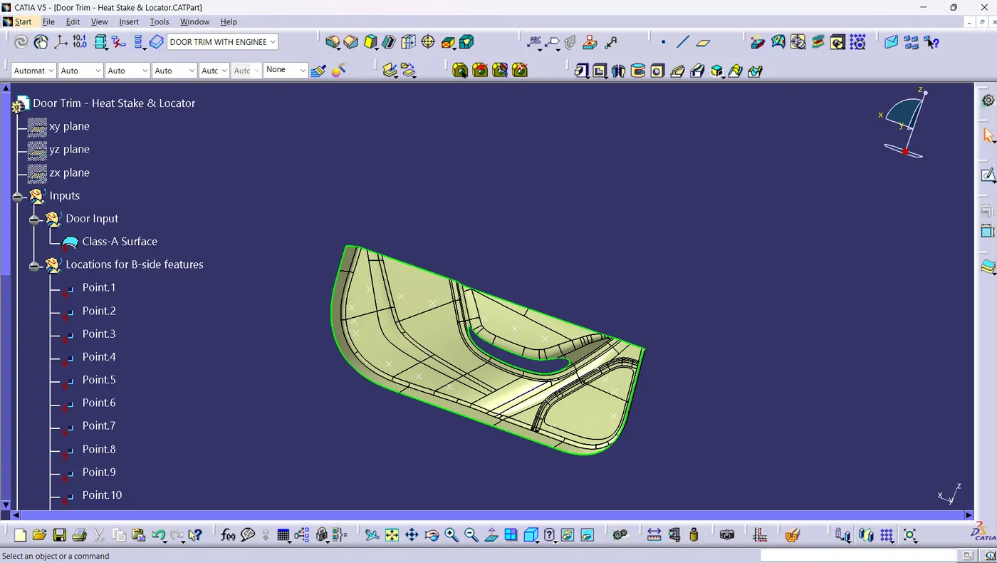
Class-A Surface of the Door Trim Lower and the points for the heat stakes are provided as input:
- Tooling Axis Creation:
We first study the Class-A surface from all directions to find the optimum direction to be the Tooling Axis.
X-Direction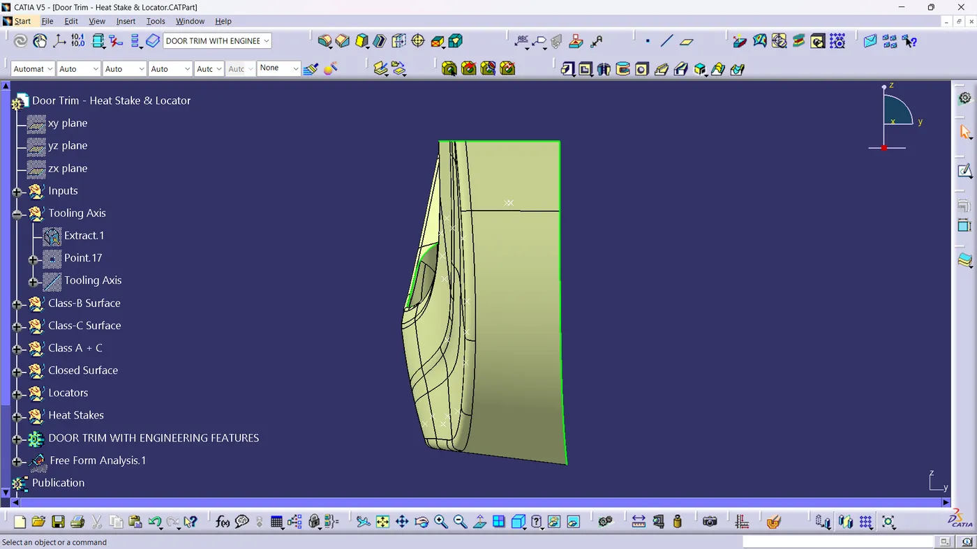
Y-Direction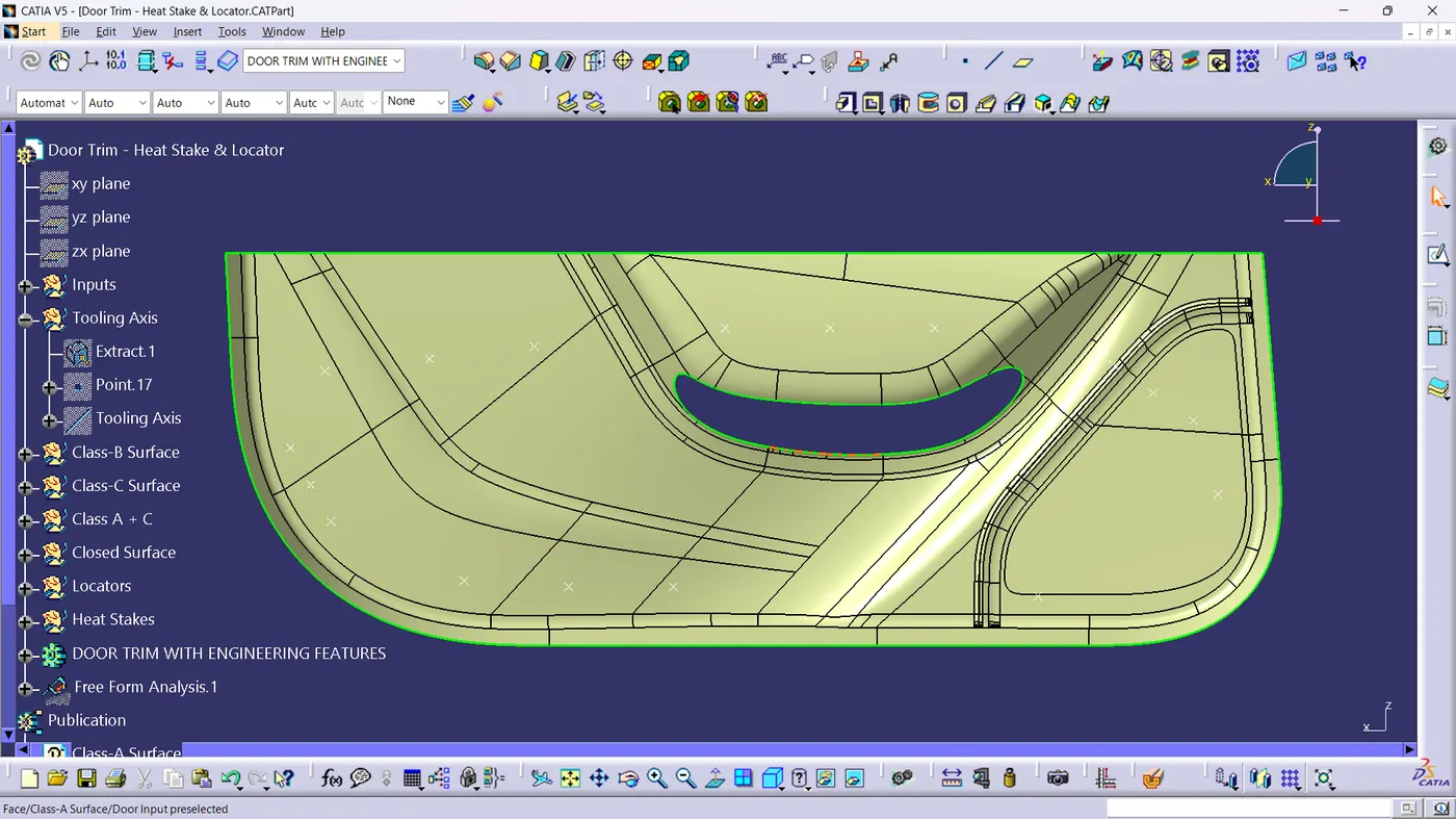
Z-Direction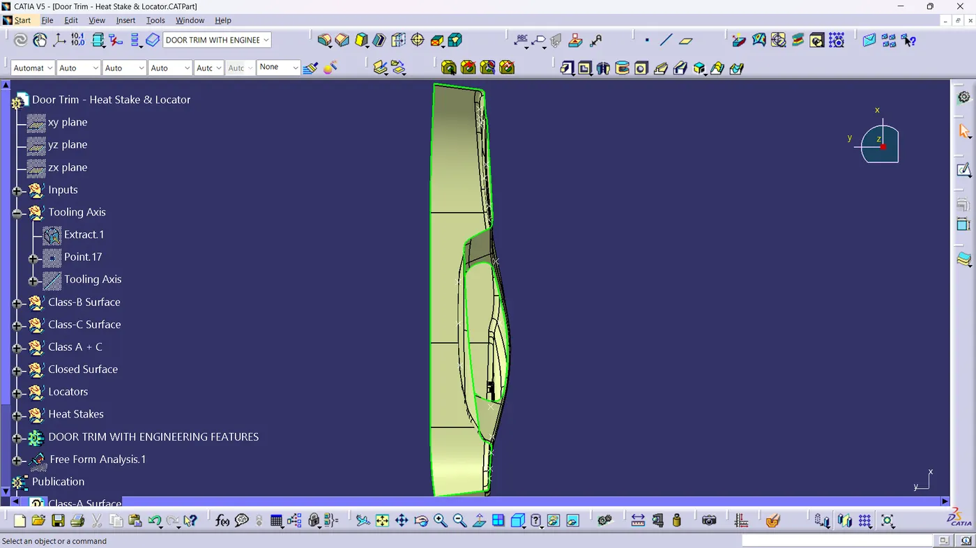
From the above images, we can see that almost all the surfaces are visible from the Y-direction Therefore, we can conclude that opening the mould in the Y-direction would give us the best access to the moulded part. In other words, we can consider Y-direction to be the Dummy Tooling Axis.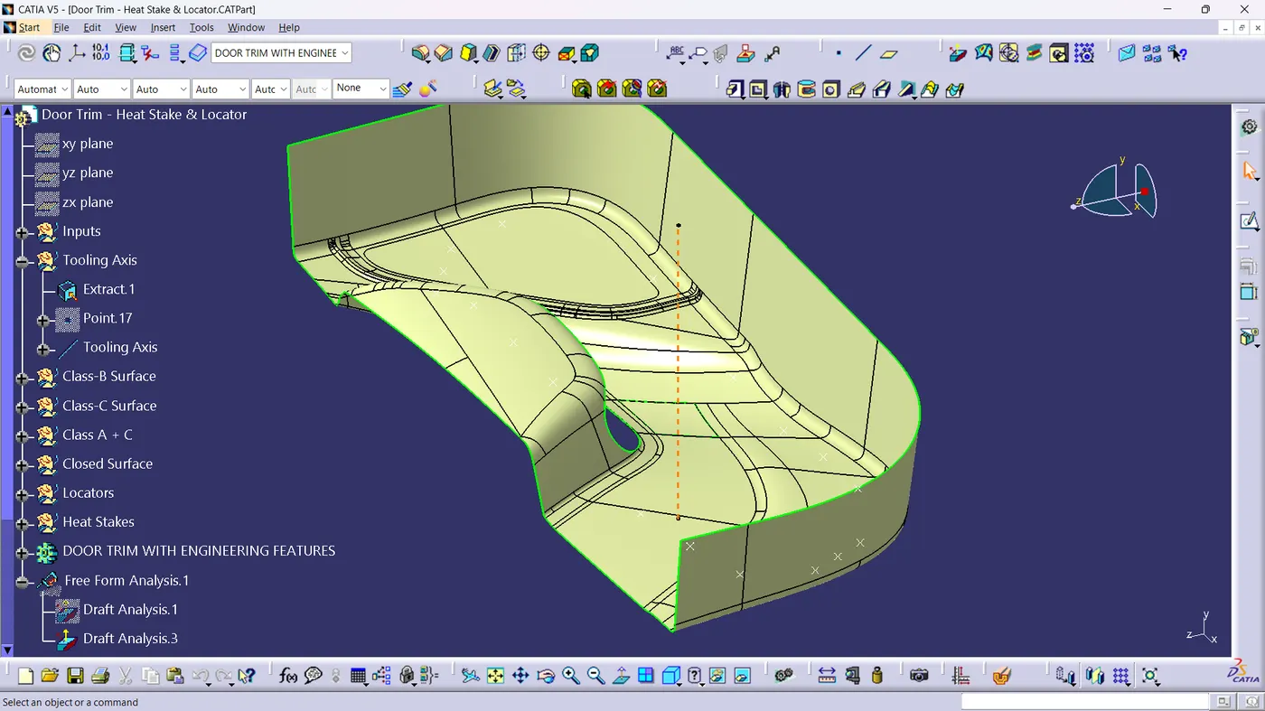
We rename the dummy tooling axis to the Tooling Axis, only after we perform the Draft Analysis using the dummy tooling axis and analyse the results. If we get all surfaces in Green as the result of the draft analysis, we can conclude that all the surfaces make an angle more than the required draft angle with respect to the dummy tooling axis. This means that we can easily extract the moulded part from the mould in the direction specified.
If however, there are any surfaces in Red, it signifies that the angle of that surface with respect to the tooling axis is lower than the draft angle required and therefore could cause problems when we try to remove the part from the mould. In that case, we try to change the angle of the Tooling Axis concerning the Class-A surface using the bisecting line method, to orient the tooling axis in such a way that the problematic surface patches make an angle of more than 3 degrees (Draft Angle) i.e. show up in green. - Draft Analysis:
To check if we have selected the Tooling Axis correctly we perform the Draft Analysis. The result of the analysis shows us, using colour codes, which surfaces have an angle lower than the draft angle with respect to the Tooling Axis (in Red). These surfaces may cause problems when we try to eject the part from the mould.
- Performing Draft Analysis on Class-A Surface using the Tooling Axis (Y-Direction):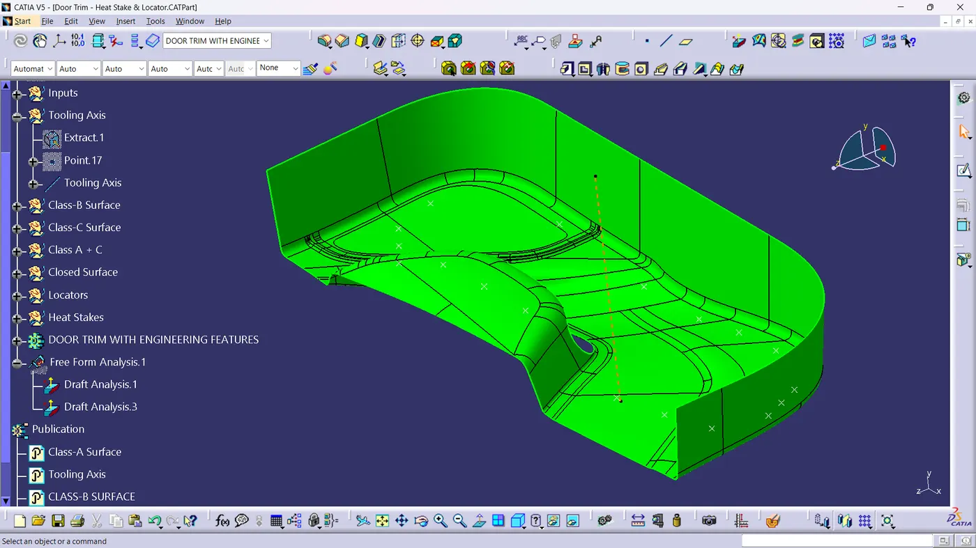
Since all the surfaces show up in green we can conclude that the Y-direction is the Tooling Axis.
- Performing Draft Analysis on the Closed Surface component using the Tooling Axis:
Once we have created the closed surface component using the Class-A, Class-B and Class-C Surfaces we perform the Draft Analysis again. This is done to check that the surfaces we created have the required draft angle i.e. the closed surface can be ejected easily from the mould.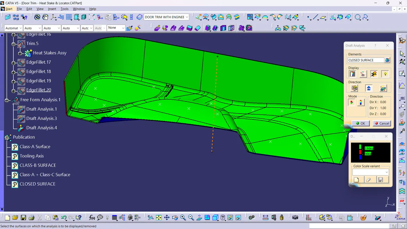
- Performing Draft Analysis on the Solid Part with the Engineering Features using the Tooling Axis: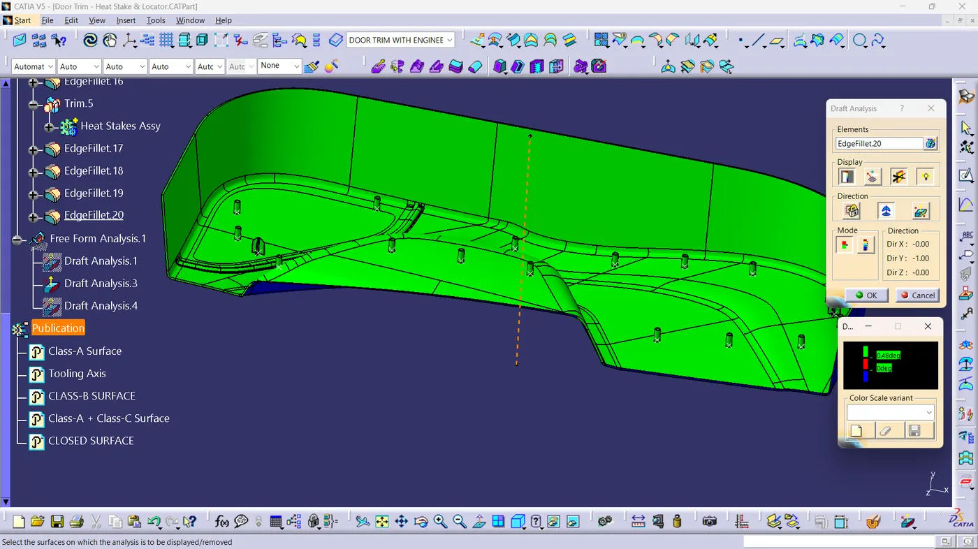
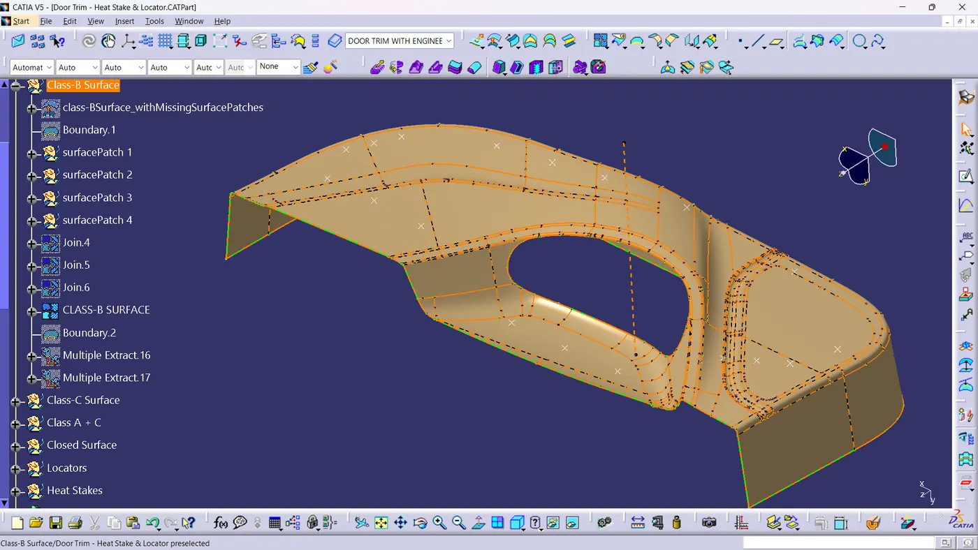
Class-B Surface:
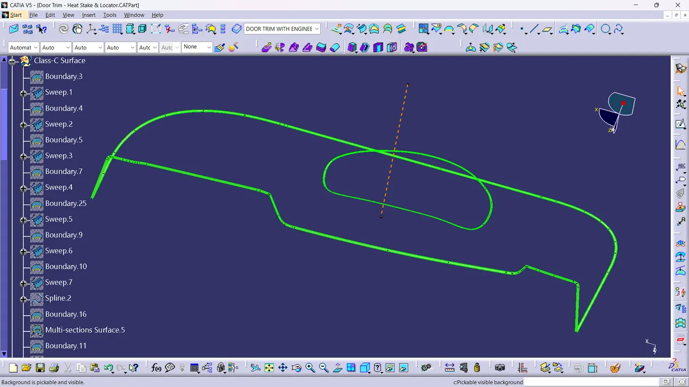
Class-C Surface:
Isometric View: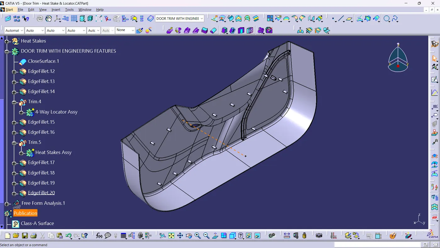
Top View:
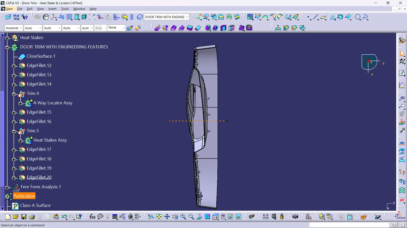
Side View:
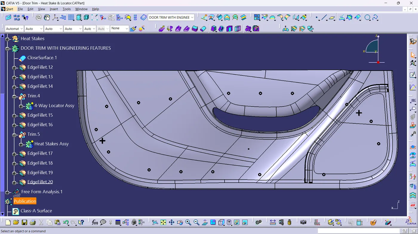
Front View: