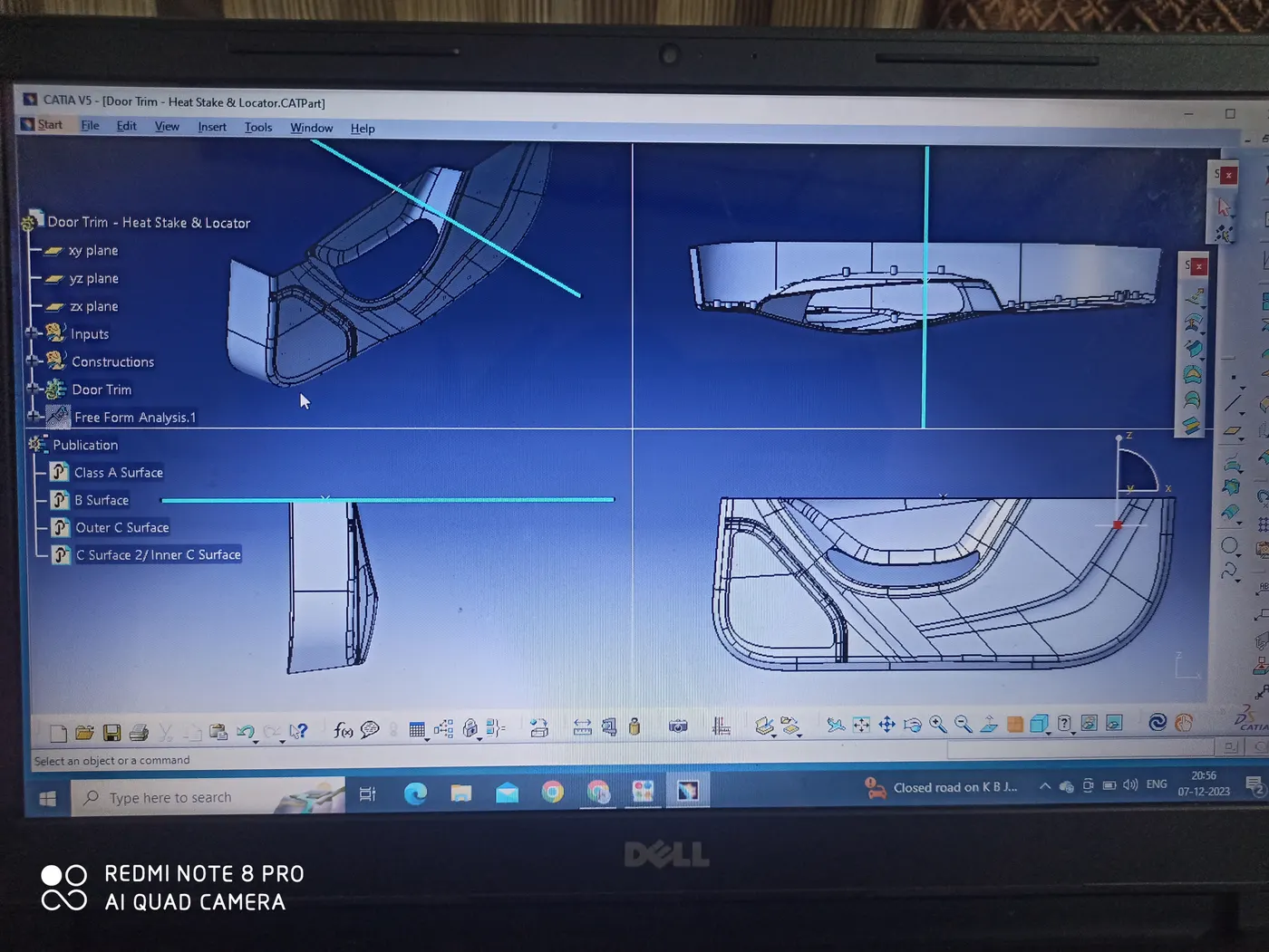
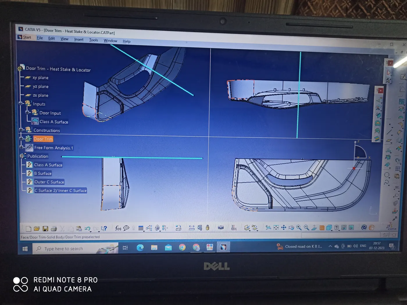
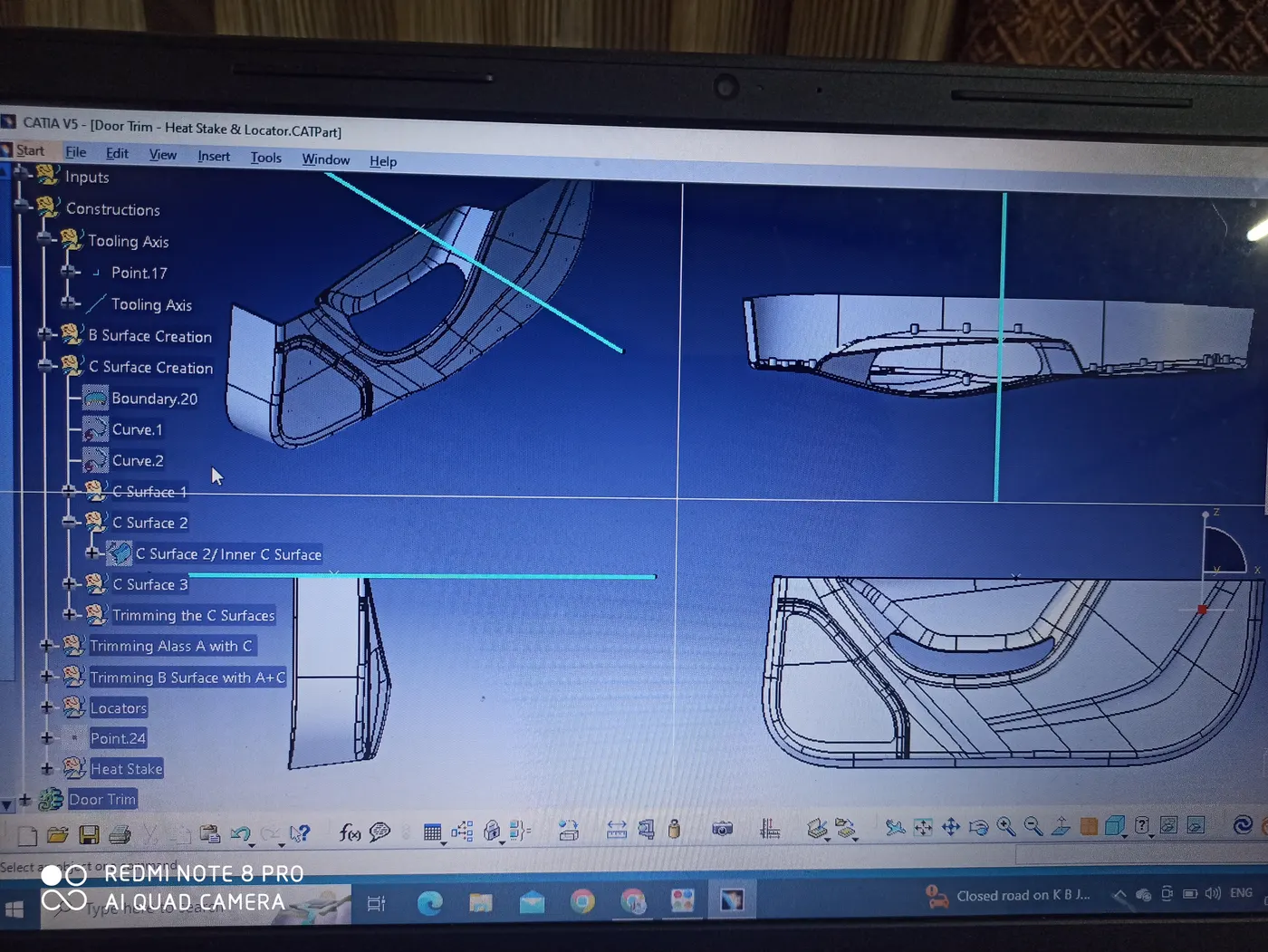
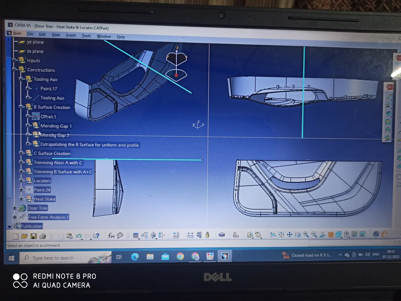
Week 10 - Challenge 3 - Door Trim Lower with Engineering Features
Design Report for Week 10 - Challenge 3- Locatotors and Heat Stakes
Tasks to be done:
-
Creation of Solid Model for Door Trim
-
Creation of Locators
-
Creation of Heat stakes
Based on the design guidelines shown in the tutorial videos.
Inputs:
-
Class A Surface
-
Positions of 4-Way Locators.
-
Positions of the Heat Stakes.
-
Component thickness is not given, hence it is assumed to be 2.5 mm.
Design Steps involved
A) Creation of Solid Model for Door Trim
i) Creation of Tooling Axis
The Class A surface for Door trim was studied thoroughly and its symmetry along xy, yz & zx planets was analyzed. Based on that the Y axis is first taken as the rough tooling axis. After carrying out a draft analysis of the Class A Surface it was noted that the Y axis satisfies the draft requirement of approximately 3 degrees for all the faces. Hence the Y axis is taken as the final tooling axis for the model. See the Draft Analysis for the Class A Surface in the model for more details.
ii) Creation of B Surface
-
The direct offset method has been adopted here, for creating the B Surface.
-
The entire Class A surface was offsetted upwards by a 2.5 mm distance (the component thickness is assumed to be 2.5mm).
-
After offsetting it was noted that the majority part of the Class A gets offsetted properly leaving 2 gaps at the fillet-like curved surfaces. The gaps can be clearly seen in the Class A offset under the geometrical set ‘Creation of B Surface’.
-
These gaps have been mended one by one and can be seen clearly in the geometrical sets named Meding Gap1 & 2 respectively.
-
The resulting B Surface looked slightly irregular along the straight boundary. Hence it was extrapolated entirely along its straight boundary to achieve a regular profile. This is the B Surface for the Door Trim Model and is published likewise.
iii) Creation of C Surface
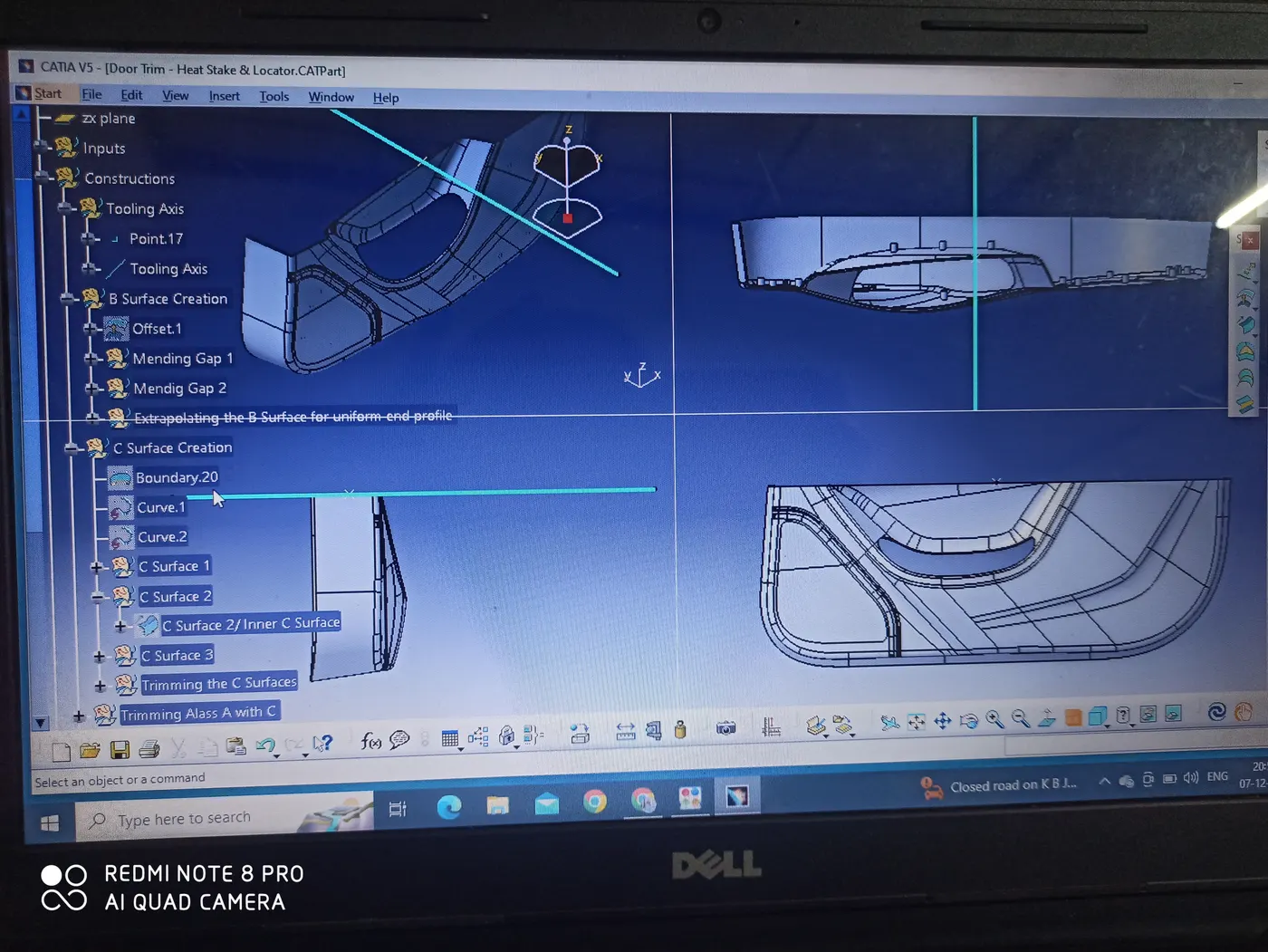
According to the given Class A surface the C Surface for the model can be divided into 3 parts.
-
C Surface 1-This is created by sweeping the corresponding boundary with a draft angle of 3 Degrees to the Tooling Axis.
-
C Surface 2- This is created by sweeping the corresponding boundary perpendicularly to the Class A Surface.
-
C Surface 3 - This is created by sweeping the internal hole boundary perpendicularly to the Class A Surface.
-
The C Surface 1 & 2 are trimmed to get the outed C Surface.
-
The C Surface 3 is the inner C Surface.
iv) Trimming The C Surfaces with Class A
-
The outer C Surface is trimmed to Class A first.
-
Then the inner C surface is trimmed to the trim of Class A & outer C Surface.
v) Trimming the A+C Surface with B Surface
-
An intersection of A+C Surface & B Surface is taken.
-
Wherever they fail to intersect, they are extrapolated and then trimmed to get the Close Surface Body for the Door Trim.
-
This Surface Body is then converted to a solid model by using the close surface command in the part workbench.
-
A Draft Analysis of this model is carried out that validates the accuracy of the model. Refer to ‘Draft Analysis of Door Trim Solid Model’ for more details.
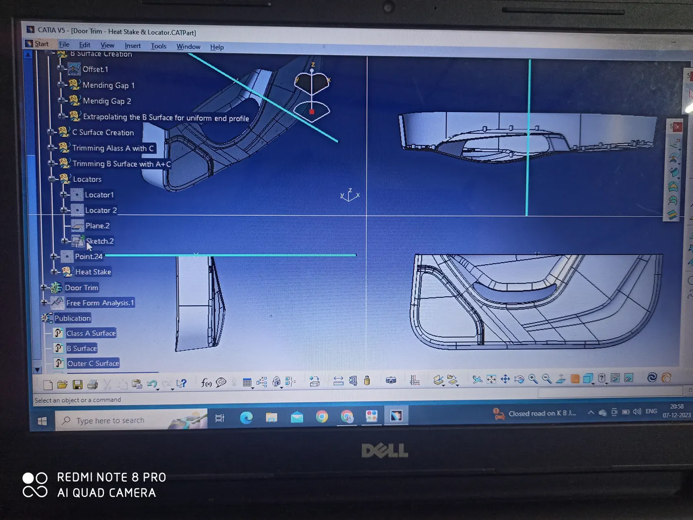
B) Creation of Locators
Based on the positions given in the input picture, 2 4-Way connectors have been provided. The design rules followed for them are the same as for Ribs.
-
A plane perpendicular to the tooling axis is inserted at the point corresponding to the first locator.
-
A sketch having the skeleton for the 4 Way connector is drawn on this plane.
-
This sketch is then padded and thickened inside a new body named as the Locators. The thickness of locator walls is taken as 1.5 mm and it is padded in both directions by 16mm.
-
A tapper of 45 degrees and 3 mm is given on all four corners of the top face.
-
A draft angle of 0.5 degrees to the Tooling Axis and bottom face of the connector as a neutral element, is given on all the vertical walls of the 4-way connector.
-
At the end, a fillet of 0.3 mm radius is provided on all sharp edges of the connector.
-
This connector is copied and special pasted with the link and then translated to the second position.
-
The 2 4-Way locators are the union trimmed to the Door Trim Model.
-
All the edges where the connectors intersect the Door trim model are also given a fillet of 0.3mm each.
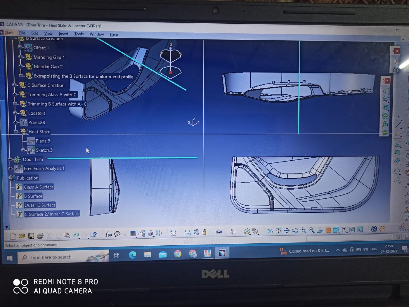
C) Creation of Heat Stakes
According to the positions given in the input Picture, a total of 16 Heat Stakes have to be provided all along the boundary of the Door Trim. We start with the first one.
-
A plane perpendicular to the tooling axis is inserted at the point corresponding to the first Heat Stake.
-
A sketch having the skeleton for the Heat Stake is drawn on this plane. (i.e. 2 concentric circles of radius difference of 2 mm). According to the rib design rules the wall thickness of the heat stake should be 1,5 mm. But we consider 0.5 mm extra to compensate for the top face width loss due to the draft.
-
This sketch is then padded inside a new body named as the Heat Stake. The pad length is 14mm in both directions.
-
A draft angle of 0.5 degrees to the Tooling Axis and bottom face of the Heat stake as a neutral element, is given on all the vertical walls.
-
At the end, a fillet of 0.3 mm radius is provided on all sharp edges of the Heat Stake.
-
This Heat stake is copied and special pasted with the link and then translated to the second position. This process is repeated 16 times to get the Heatstakes at all indicated positions.
-
All the Heat Stakes are assembled inside a new body named ‘Heat stake Assembly’ and trimmed to the solid model for Door trim one by one.
-
All the edges where the Heat Sakes intersect the Door trim model are also given a fillet of 0.3 mm each.
The model and corresponding geometric Sets can be referred to for details whenever necessary. The pictures of the Model are also attached to this report for better understanding.