Week 10 - Challenge 3 - Door Trim Lower with Engineering Features
1. Creation Of Main Tooling Axis :
- First checked for suitable direction for tooling .
- A line normal to surface is created which is clearing the tooling .
- Hence consider as Tooling axis.
2. Draft Analysis of class A :
- Before drafting we have to make sure that in the view mode it is selected for the materials .
- After selecting draft analysis tool need to drag the compass and position it to the main tooling axis
- Lock the compass and select on the component
- change the minimum draft to 3deg.
- use running point tool to check the component.
- And Found Clearing all Areas.
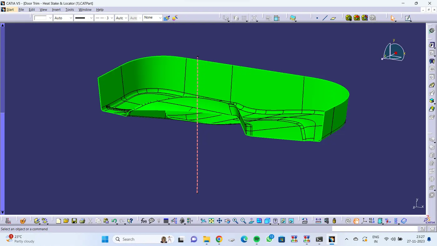
3. B Surface :
- Offseted 2.5 mm from Class A Surface
- Found 5 Patches in the surface
- Worked on each patches , Extracted each surfaces and Extrapolated and Trimed and given Suitable fillet
- Extrapolated B surface for suitable trim .
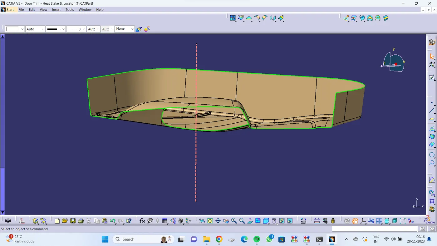
4. C Surface & Final Trim :
- Used Sweep Option with Draft direction 3 deg and Reference surface 90 deg on required areas in Class A Surface and trim all as one surface , Joined C surface with A surface.
- Trimmed C join A surface with Extrpolated B surface and got a closed surface
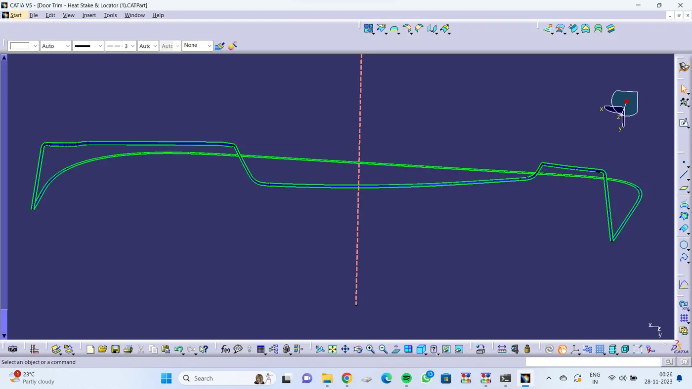
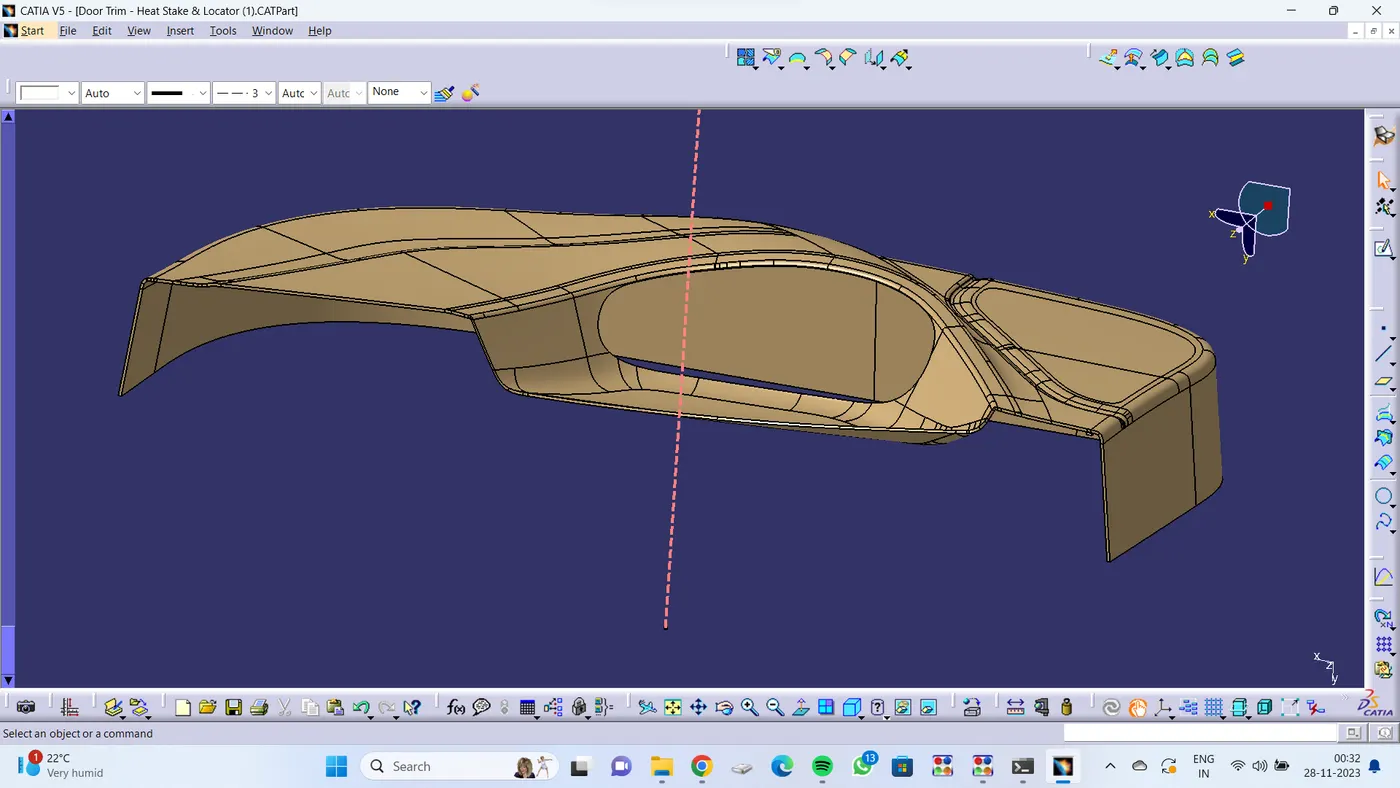
5. Closed Part :
Used Closed Surface option in trimmed surface and formed closed Body..
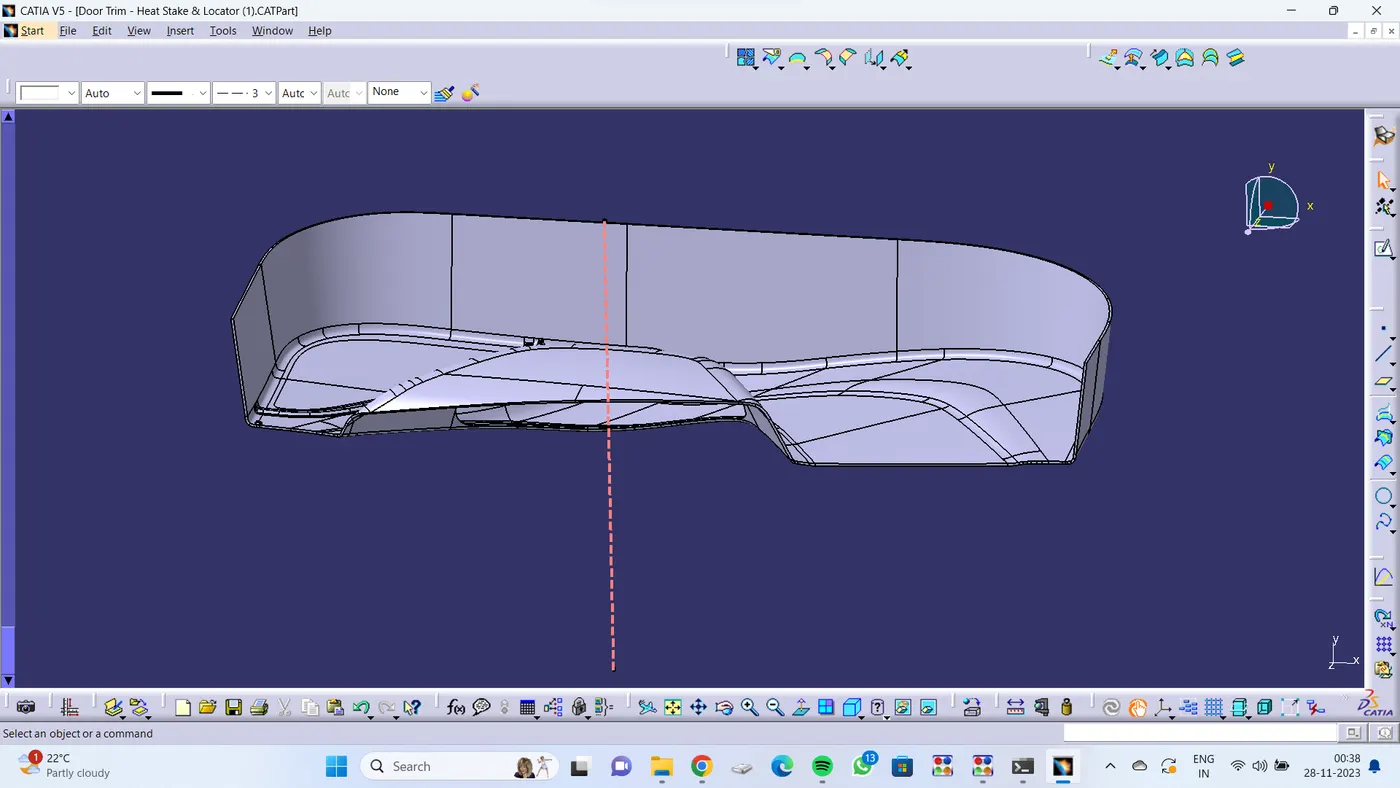
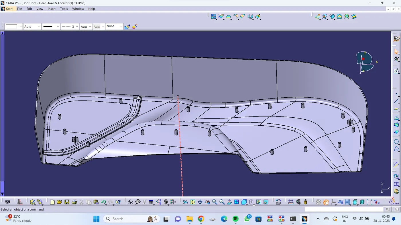
6. Engineering Features:
Created Heat Stakes And Four way Locator in given Areas following design rules and given draft of 0.5 degrees and trimed with main Body
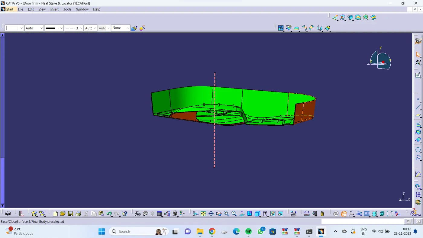
7. Draft Analysis of Final Component :
- we have to make sure that the view mode is in materials.
- Drag the compass and position it to the main tooling axis
- Fix the compass using lock option.
- Draft Angle of 3 deg is given .
- use running point tool to check draft.
- Using colour codes checked the draft and found good .
- For Checking Engineering Features compass is positioned on main tooling axis to check the Heat Stakes & Locators in main part.
- Draft angle of 0.5 deg is given.
- used running point tool to check
- Using colour codes checked the draft and found good.
Thank You..