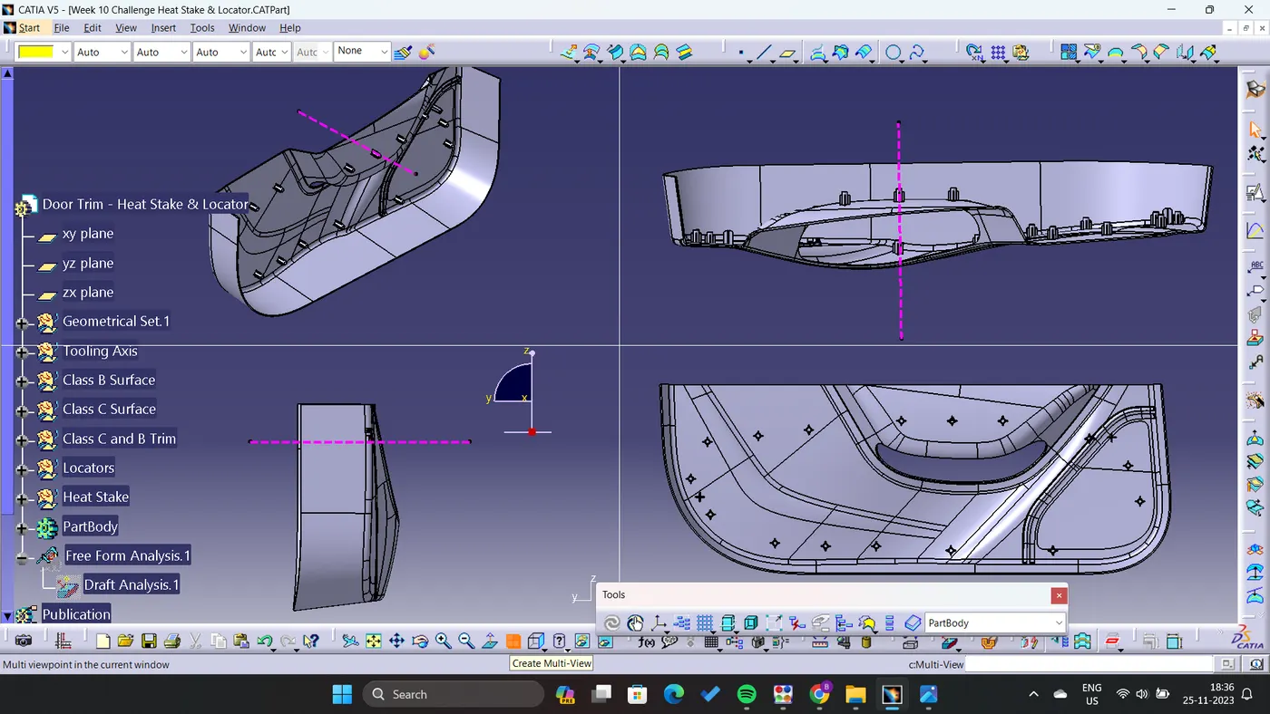
Week 10 - Challenge 3 - Door Trim Lower with Engineering Features
Draft Analysis:
- Visualised the Class A Surface, checked the axis that will clear all edges and slots.
- Created the Main Tooling axis in Y-direction by taking point on the curve as highlighte in Pink color.
- After the tooling axis is created, to perform Draft Analysis go to Insert- Analysis- Feature Draft Analysis.
- First aligne the Compass with the Tooling Axis and lock it their.
- After that set the range of Draft as 0 to 2.5 degree with respective, it will show the results.
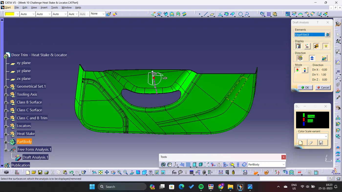
- Class A surface shows the draft of more than 2.5 degrees, highlighted in green color, as shown in image below.
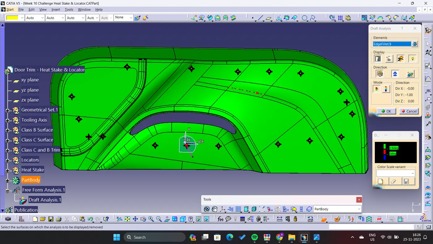
- B side Surface also shows the draft of more than 2.5 degree, except heat stakes and locators, as shown image below.
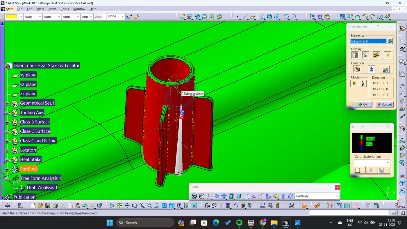
- Draft analysis of Locators: Top surface have enough draft but the verticle walls have 0.5 deg draft, shown in red colour in image below.
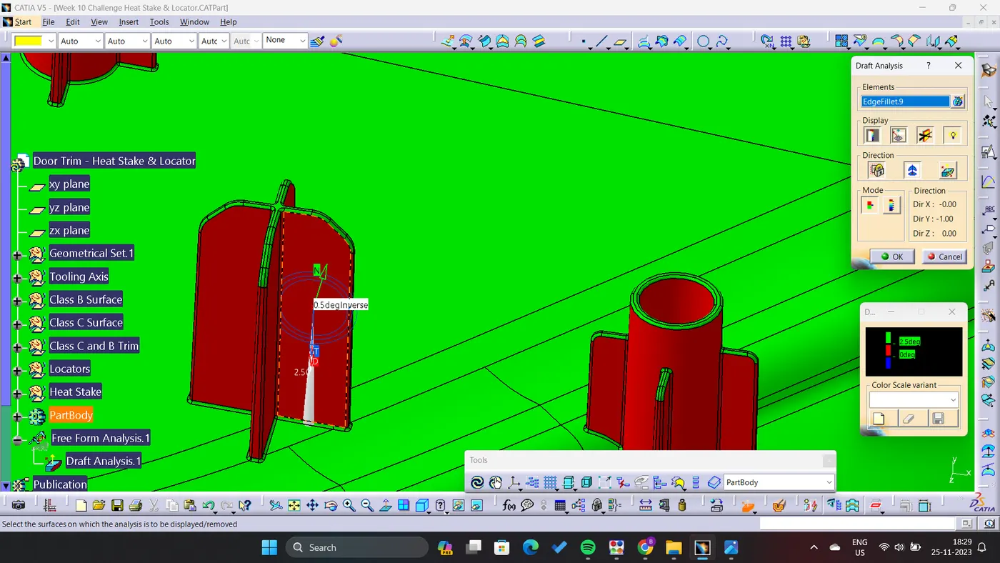
- Draft Analysis of Heat stakes: same as locators, Heat stake's top surface alsso have enough draft but the verticle walls have 0.5 deg draft, shown in red colour in image below.
- Different Views of Final Component: