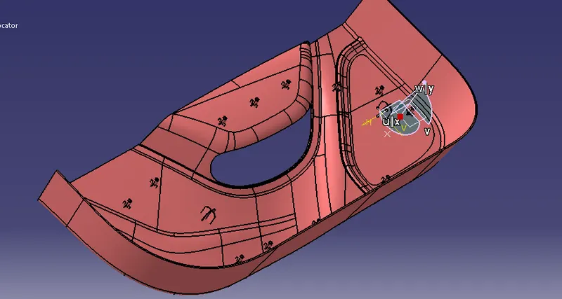
Week 10 - Challenge 3 - Door Trim Lower with Engineering Features
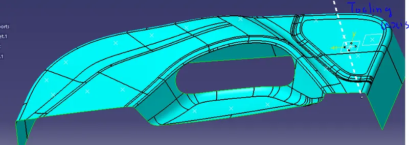
CREATING TOOLING AXIS.
- First, we create a plane on the surface. Then draw two lines based on the projection of class A or using the intersection of the point’s method.
- Now Using the Normal to-the-surface method, We have to create the tooling axis.
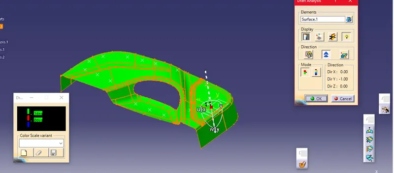
DRAFT ANALYSIS FOR SURFACE A
- After creating the Tooling axis, I checked for the draft analysis by clicking insert-->Analysis-->Draft analysis.
- Surface A Passed the Draft Analysis Test.
CREATING CLASS B AND CLASS C SURFACES.
- Then I created the Class B surface, Using the following commands.
- Offset.
- Trim.
- Multi-surface.
- Boundary.
- Split.
- Join.
- Untrim.
- Extract.
- Multi-Extract.
- Then I created the Class C surface, Using the following commands.
- Sweep.
- Boundary.
- Smooth- Surface.
- Multi-Extract.
- After creating the Class B and Class C Surface, I Joined the Surface A and Surface C and Trimmed them with Surface B.
Join A+C.
Trim A+C-B.
- After creating the Closed Surface, I checked for the closed surface using the Boundary Condition.
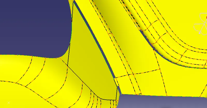
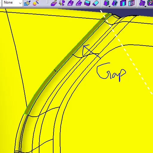
While offsetting there, a gap is formed.
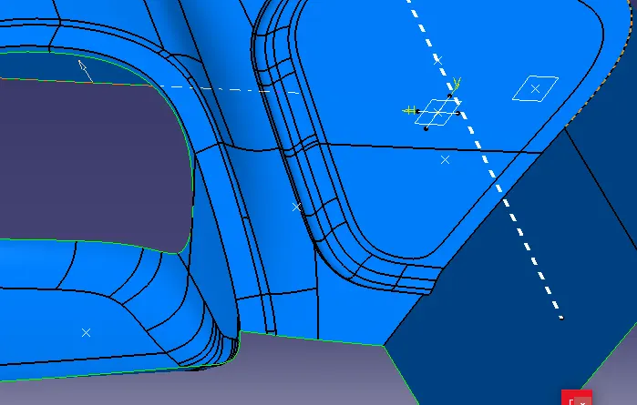
All the gap is filled using the Multi-Surface and Extrapolate commands.
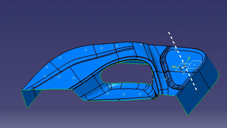
SURFACE B
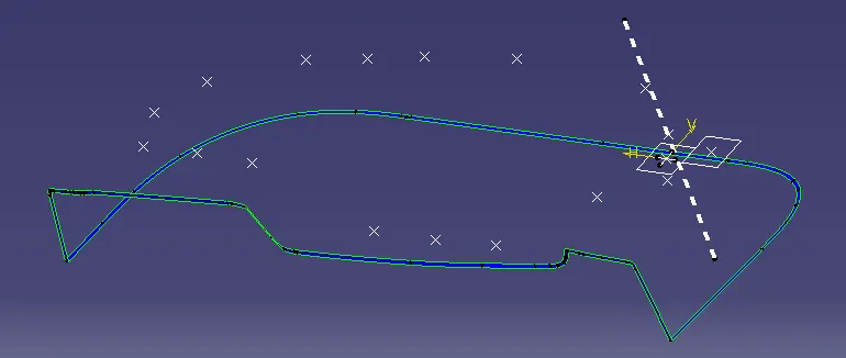
SURFACE C
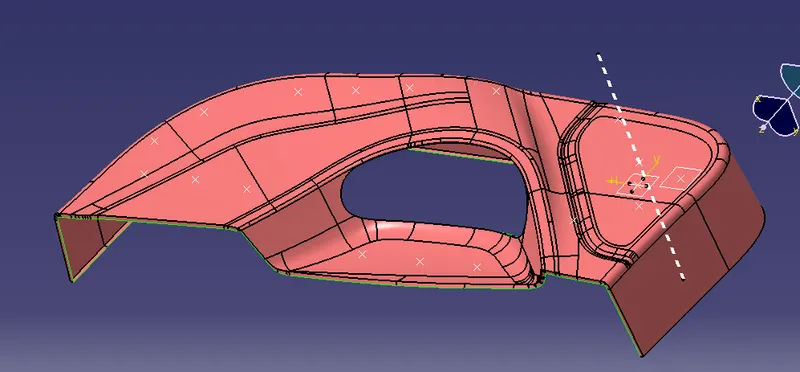
SURFACE A+C(jOINING A AND C SURFACE USING JOIN COMMANDS)
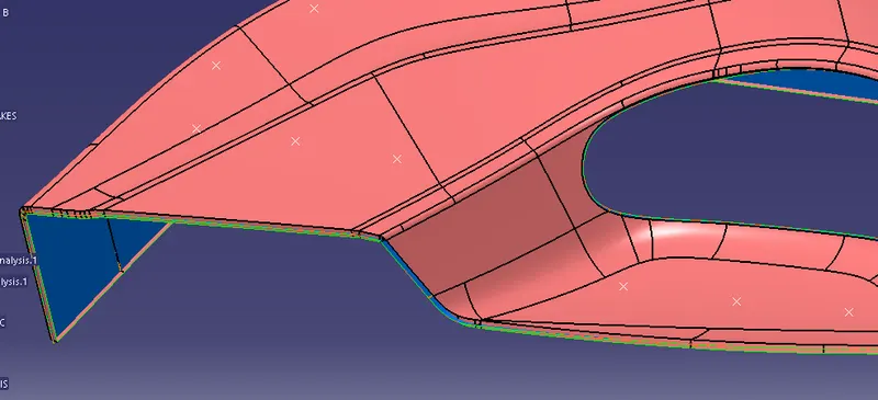
TRIMMING (A+C) AND B
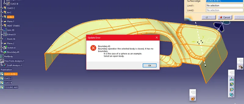
SURFACE A+B+C (Checked for closed surface)
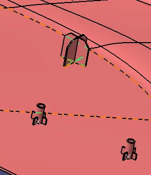
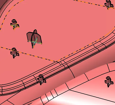
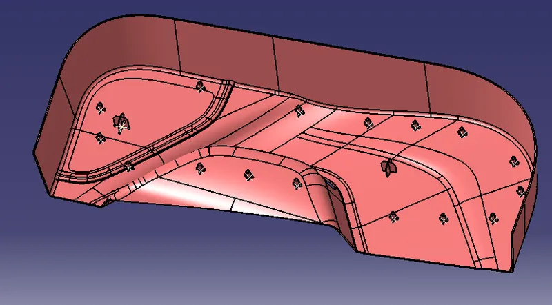
FINAL PRODUCT WITH HEAT STAKES AND LOCATORS
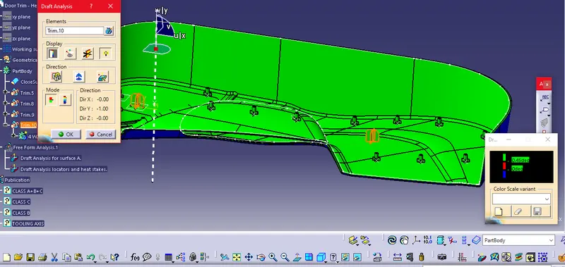
DRAFT ANALYSIS FOR THE FINAL PRODUCT
- After creating the closed surface, I checked for the draft analysis by clicking insert-->Analysis-->Draft analysis.
- And My Closed surface passed the draft analysis test for the heat stakes and locators.
DIFFERENT VIEWS
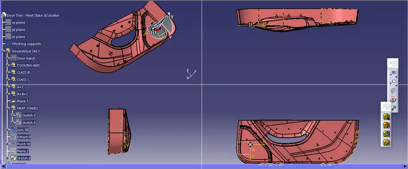
ISOMETRIC VIEWS