Week 10 - Challenge 3 - Door Trim Lower with Engineering Features
DOOR TRIM LOWER WITH ENGINEERING FEATURES
AIM:
- Write A detailed report explaining the draft analysis of class A surface, final component and engineering features
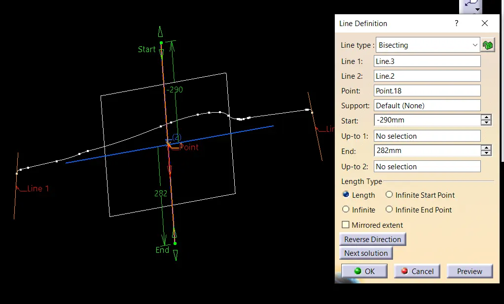
- An explanation should be given on the way of creating the tooling axis, particularly the Bisecting method
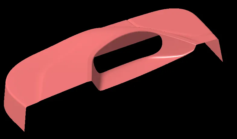
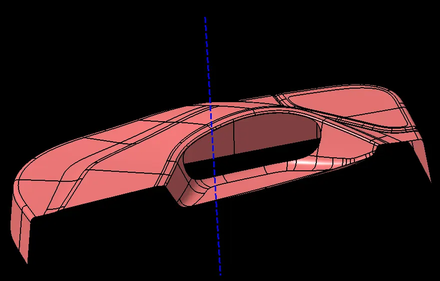
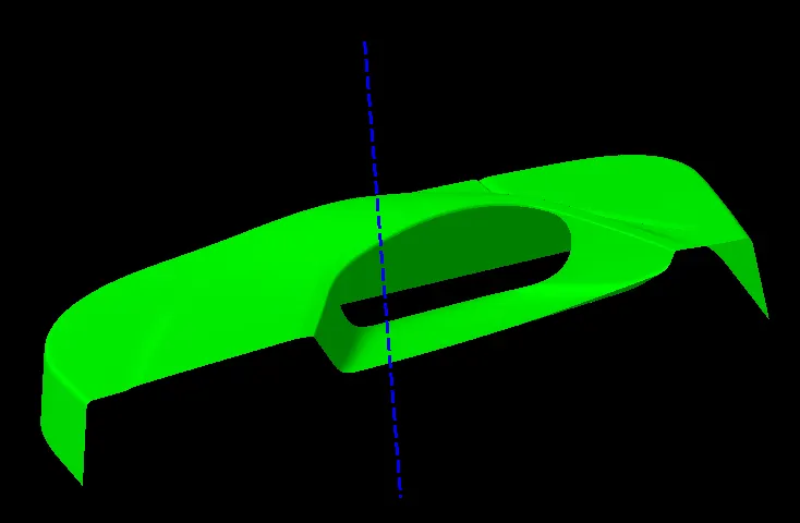
GIVEN CLASS A SURFACE
Tooling axis
It is defined as the direction in which the core and cavity open. Here I created tooling axis using the bisecting method. Selection of the direction of the tooling axis depends on the ease at which components can be easily ejected
Steps to create tooling axis
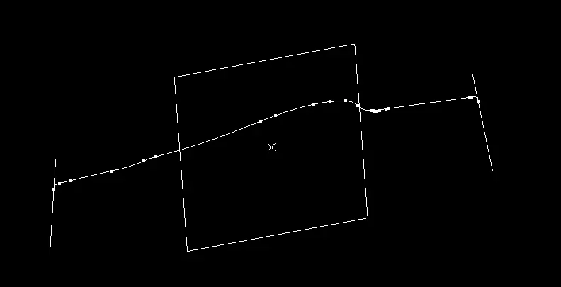
create a point on center of gravity of class A surface And create a XY plane on that point now creating an intersection on a that plane with the class A surface
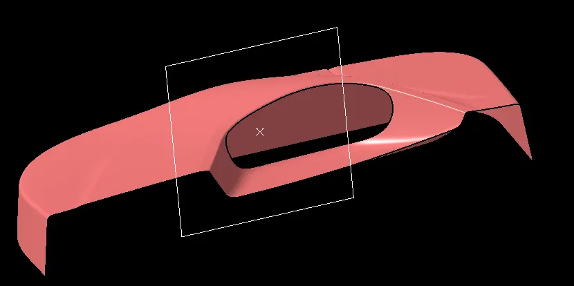
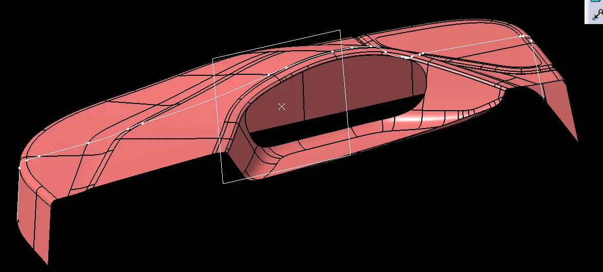
Using the intersection, lines will be created along the inclined walls, these lines are used for creation of tooling axis by bisecting method where the two lines and point will be selected as inputs. Name this Line as main tooling axis
Draft analysis
Before going to drat analysis go to customized view parameter >under mesh >check material and then click ok.
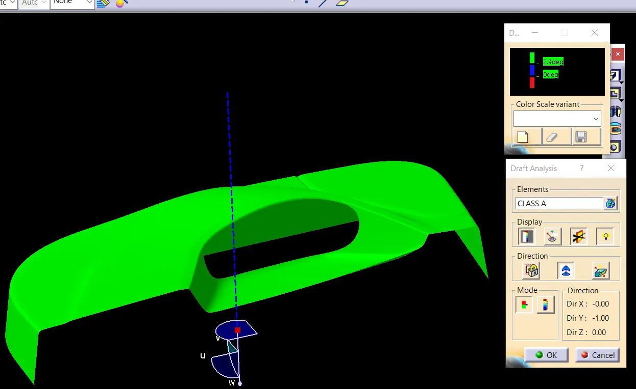
- Now for draft analyses go to insert » analysis » feature draft analysis.
- Use the compasss to define the draft direction.
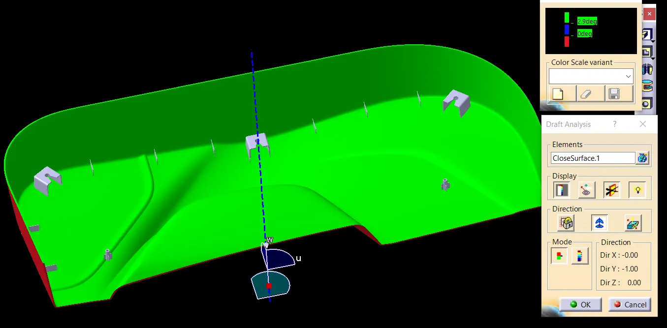
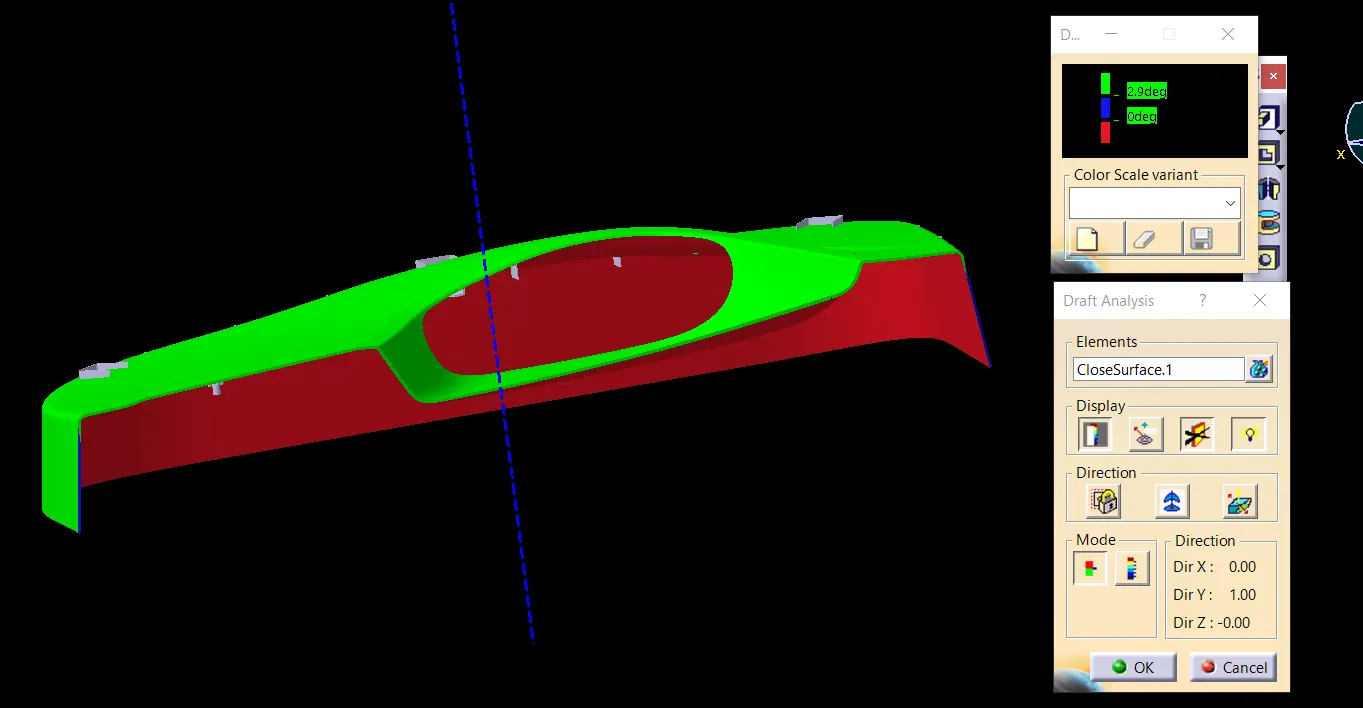
- Nominal draft considers is 3 degree
CLASS A
All areas are within minimum draft of 3 degree
CLASS B
All areas are within minimum draft of 3 degree
Class C
All faces of C surface clearing 3 degree draft
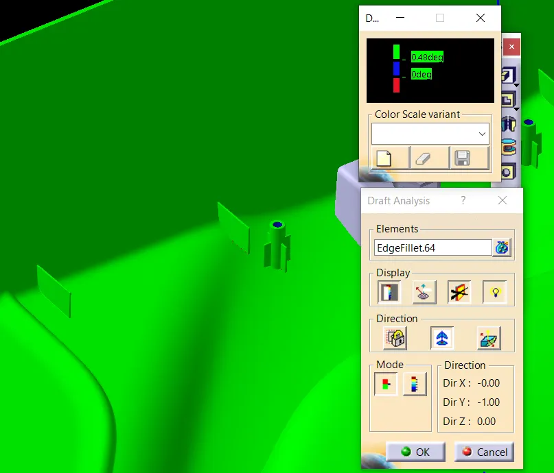
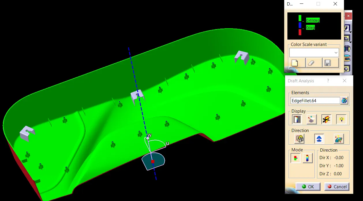
HEAT STAKES
All heat stakes clearing the draft of 0.48deg with respect to tooling axis
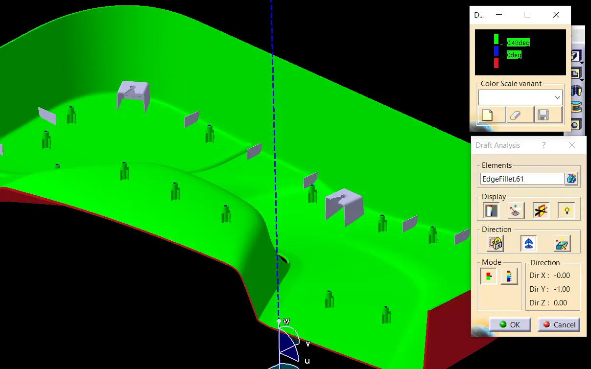
RIBS
All ribs clearing the draft of 0.48deg with tooling axis
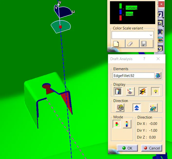
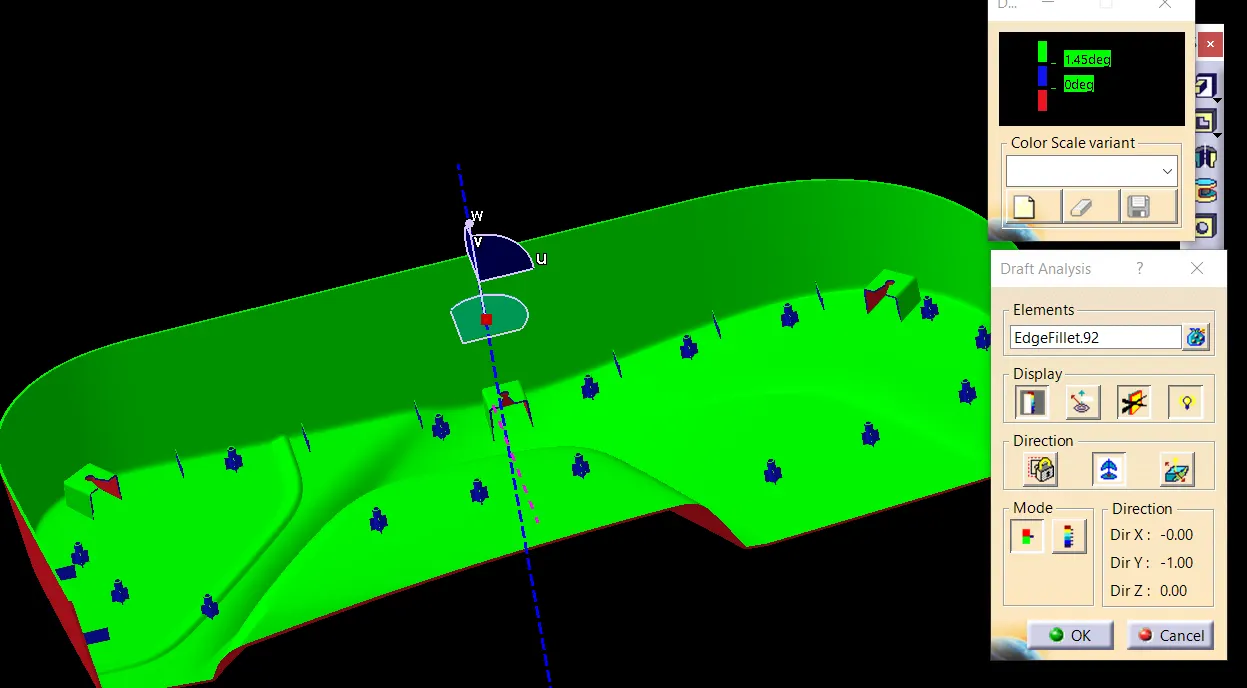
DOG HOUSE
WITH TOOLING AXIS
FOR DRAFT 1.45deg
WITH SIDE CORE AXIS
FOR DRAFT 0.48deg
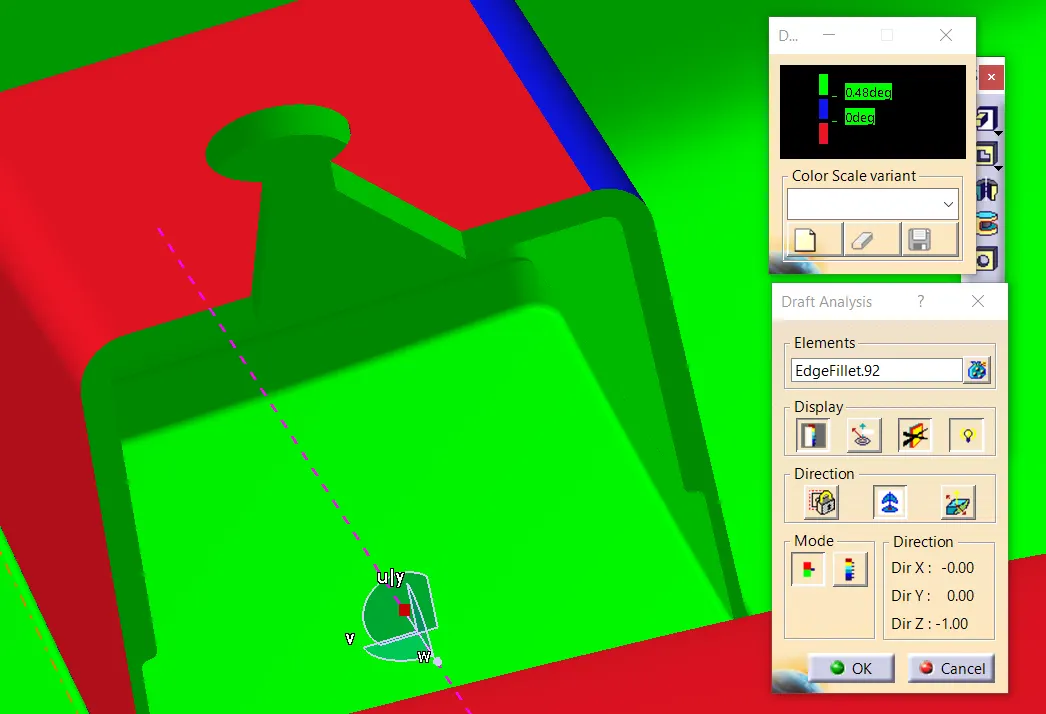
DRAFT ANALYSIS OF PART BODY
FOR 3deg DRAFT
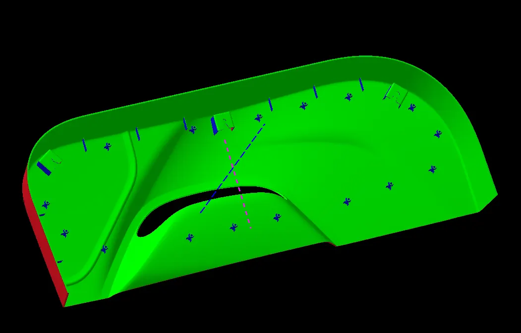
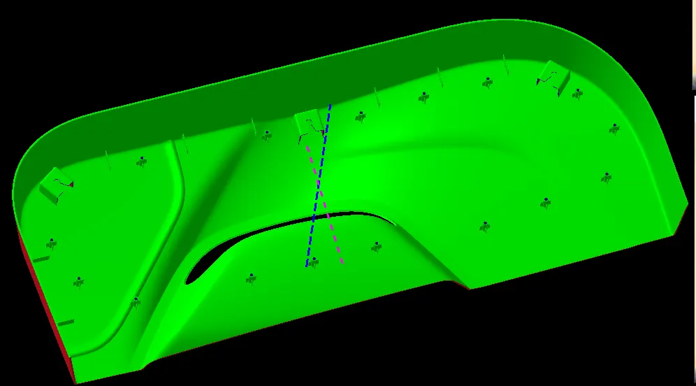
FOR 0.48deg DRAFT
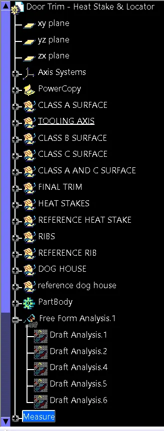
TREE STRUCTURE