Week 10 - Challenge 3 - Door Trim Lower with Engineering Features
DOOR TRIM LOWER WITH HEAT STAKES AND THE LOCATOR:
AIM:
To create the door trim lower solid component through given class A surface and then consider the design rule to create heat stakes and locators in the door trim solid part.
Procedure:
- Create the tooling axis and then check the draft analysis
- Create a class B & C surface through the Class A surface
- Create the solid component and check it is draft analysis.
- Create heat stackes and locators considering the design rule.
Tooling axis:
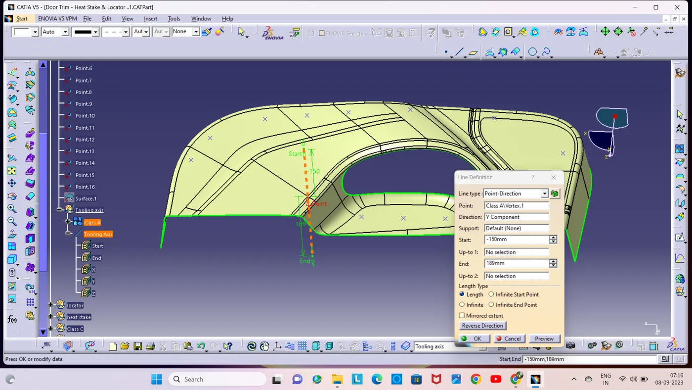
A tooling axis is created on the mold in the direction of openinig and closing the mold and cavity.
I select the center surface and extract the surface and then create point on the surface. Next i created a line through the point using the point and direction line command.
Draft analysis on class A surface:
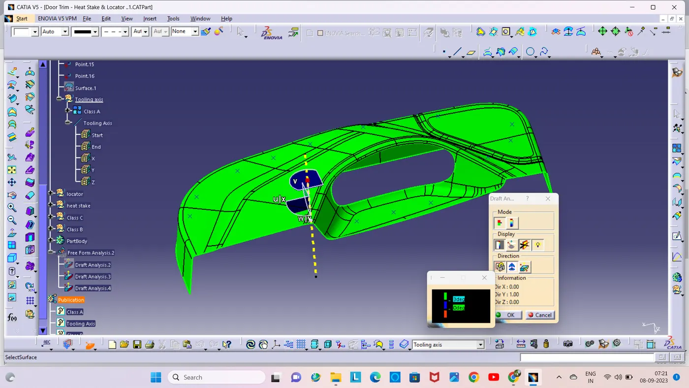
Class A surface is checked with the help of draft analysis and Tolling axis.
Given a surface angle of minimum 3 degerees, the whole component truns green. If the component truns green, Go to next operation.
Class B surface:
The Class-B surface is the secondary surface in the plastic component. Class B-Surface is extracted from the A-surface and it is offseted at 2mm in downward direction.
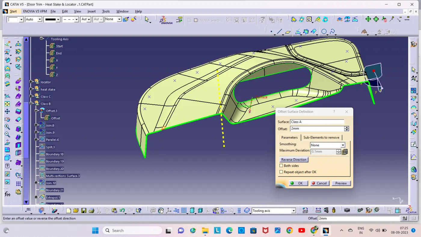
Some parts were missing from the created class b surface so i used extract ,extrapolate and multi sections surface commands to fix that.
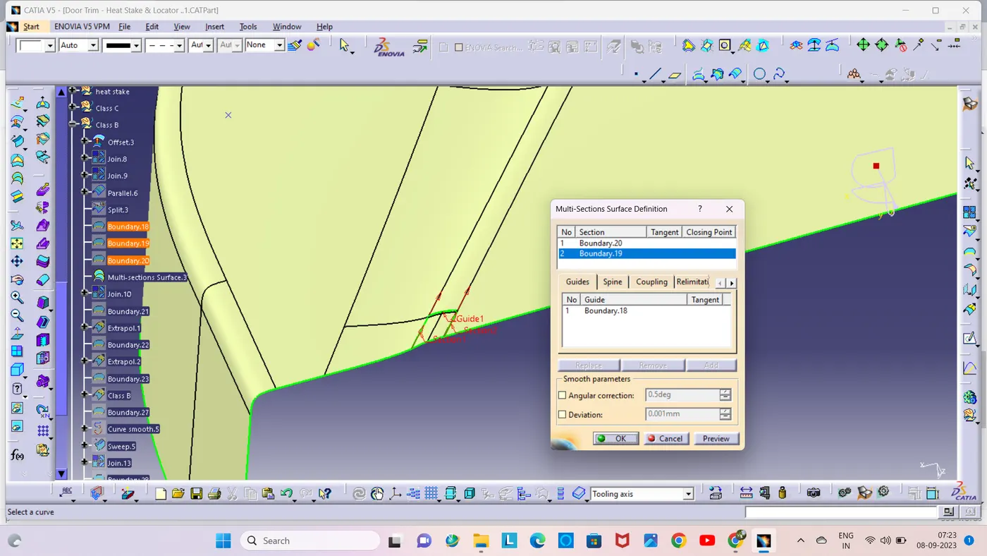
finally created a Class B surace and then used the boundary command to check for any irreguler surface or gap, if there no defect, go to the next step.
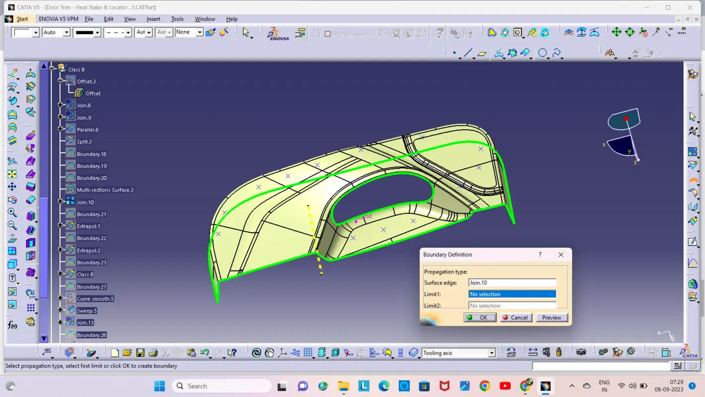
Class C surface:
To create a Class-A outer boundary with the boundary command, Then Create a Class-C surface using the sweep command over the boundary.
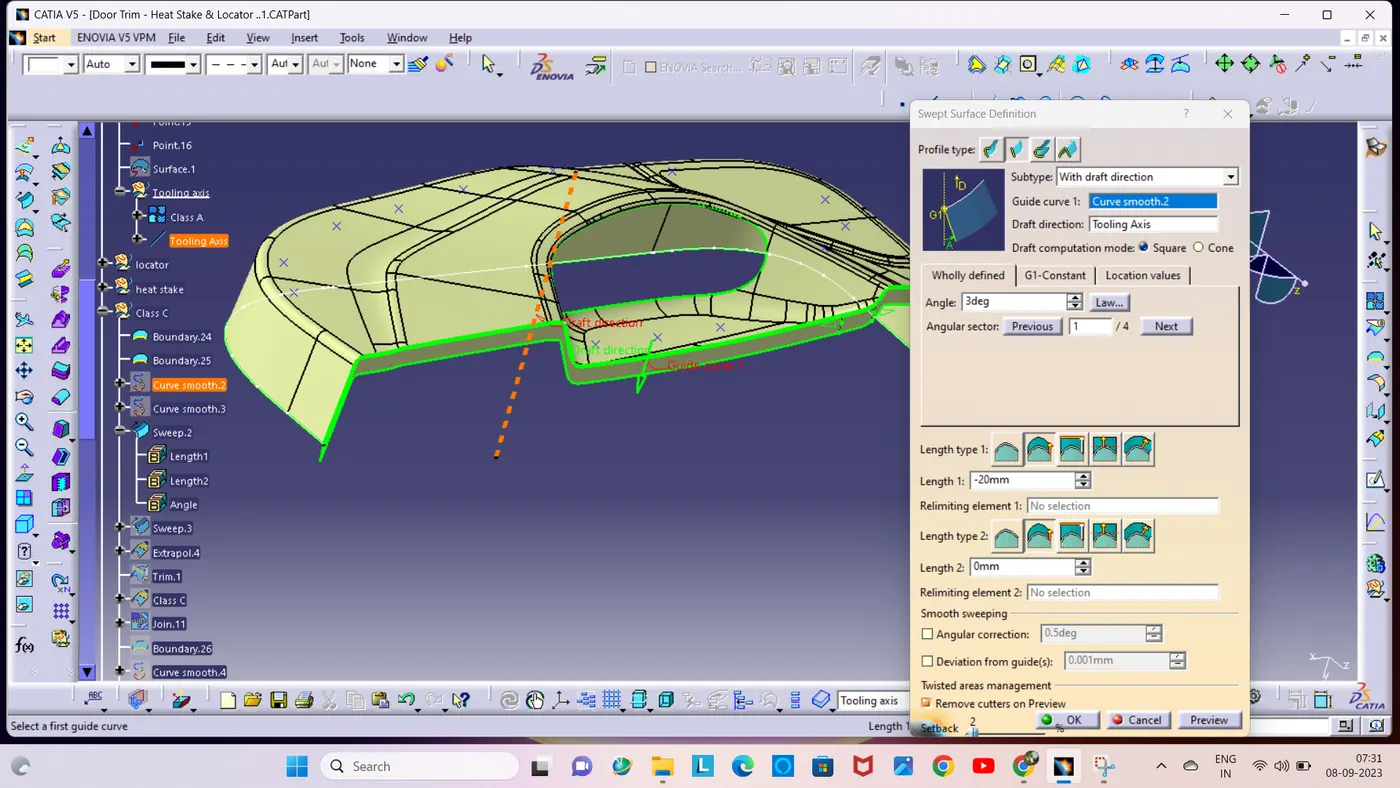
The Class-C surface is created by giving a minimum draft angle of 3mm in the sweep command.
Now, let's combine both the Class-A and the sweep surface to get a complete Class-C surface.
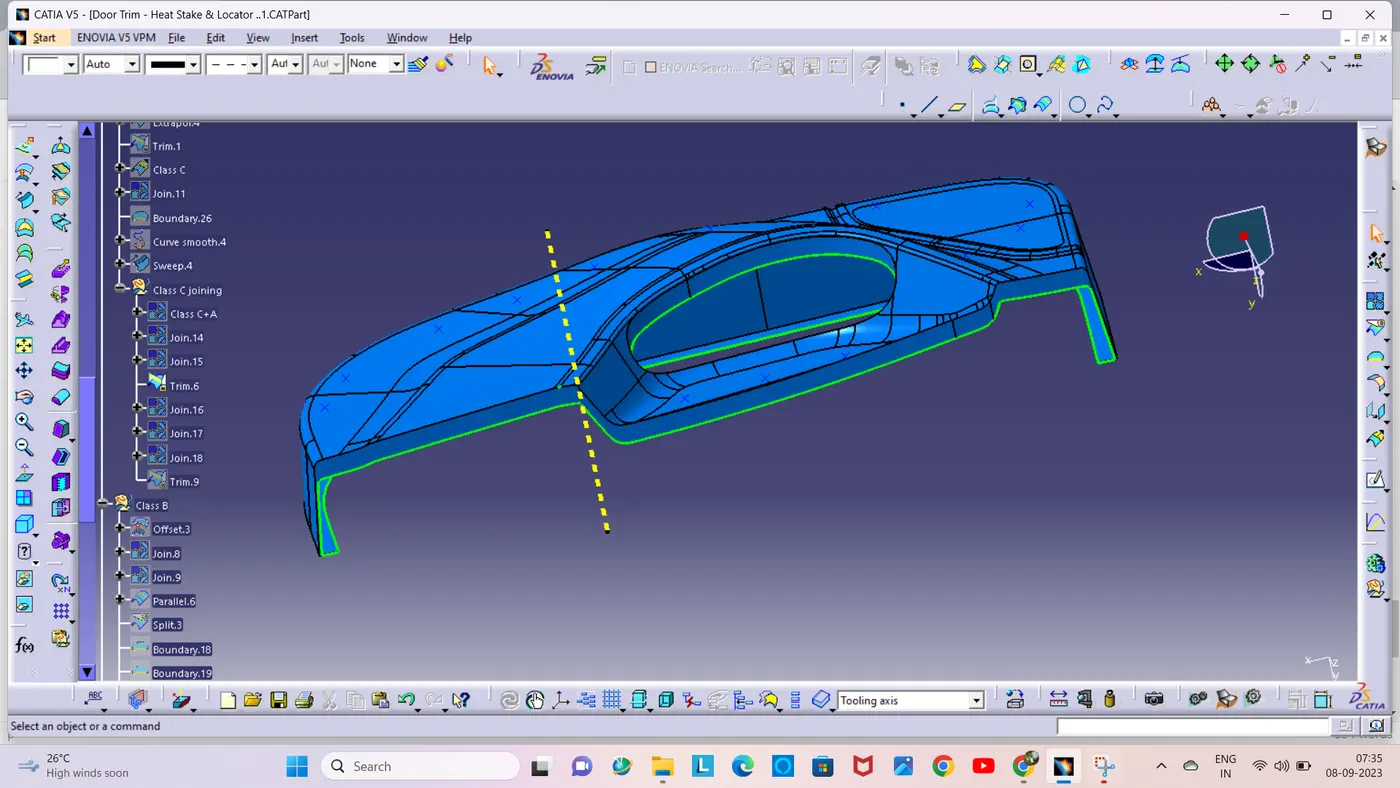
Trimmed surface:
Check that the Class-B surface intersects the Class-C surface correctly.
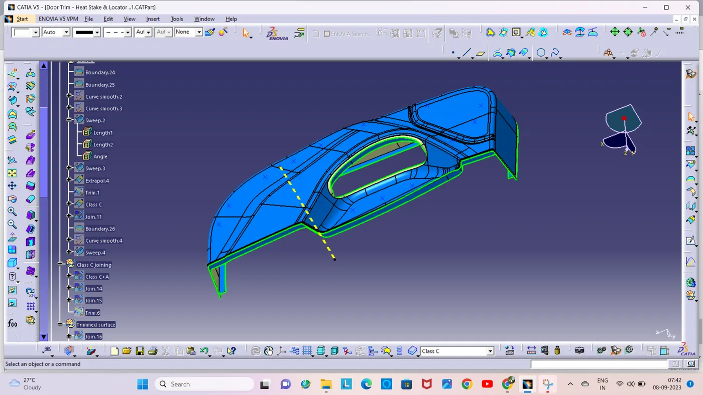
A trimmed surface is created using the Trim command in Class-C and Class-B surface.
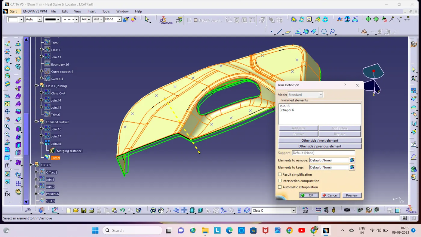
Solid Part;
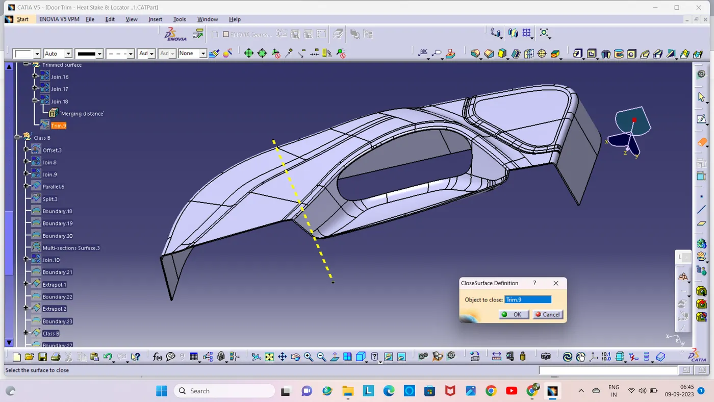
To check the trim surface created using the boundary command, if it does not get the boundary, got a closed surface.
A solid part is created using the closed surface command on a trimmed surface.
Creating Locators:
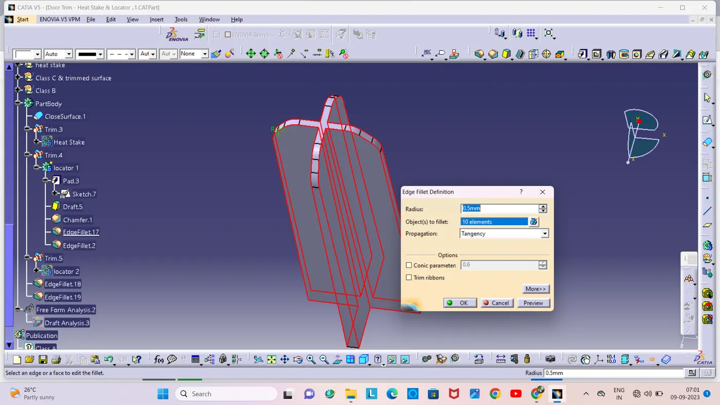
First i created two points on the created solid part, then i created a sketch inn that solid part centered on that point using position sketch.
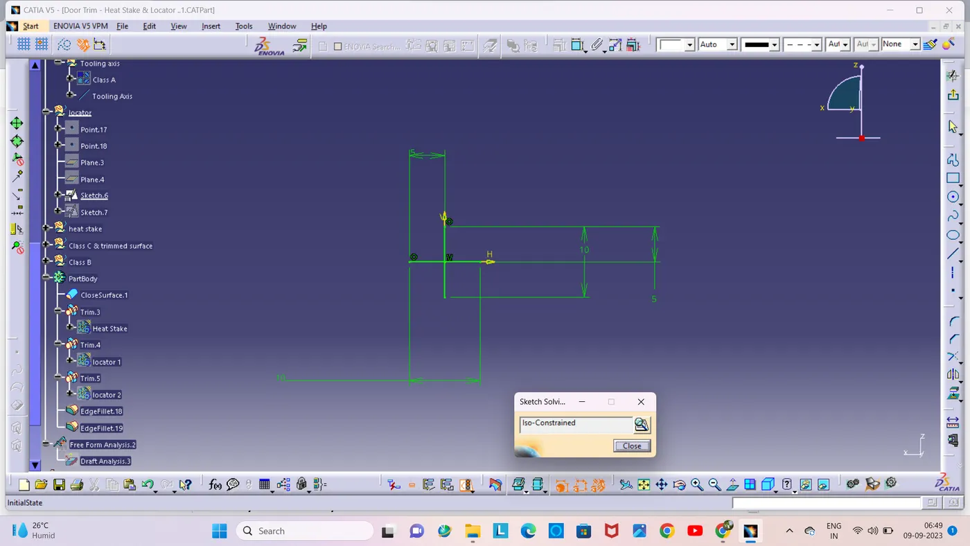
Then i used the sketch with help of pad command and i pad it 20mm height, made it 1mm thick and drew 0.5 degrees in the direction of the tooling axis.

I gave a 3mm chamfer with a 45 degree incline and then a 0.5mm radius fillet.
Creating Heat stakes:
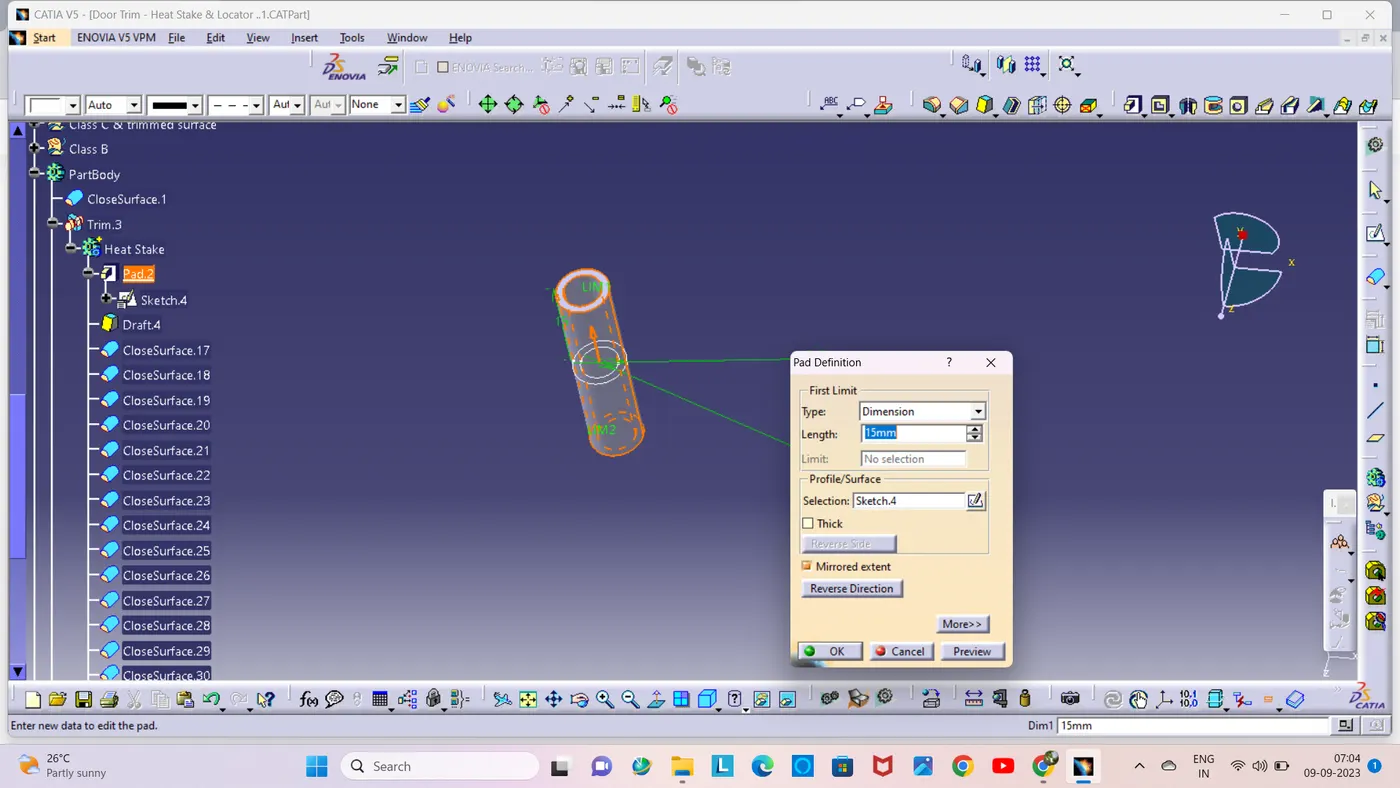
To create the heat stakes, I draw a sketch on the surface. After the creation of the sketch, I pad it to 15mm height and I gave a draft angle of 0.5deg on both sides (inside and outside) and then I gave a fillet with a 0.25mm radius.
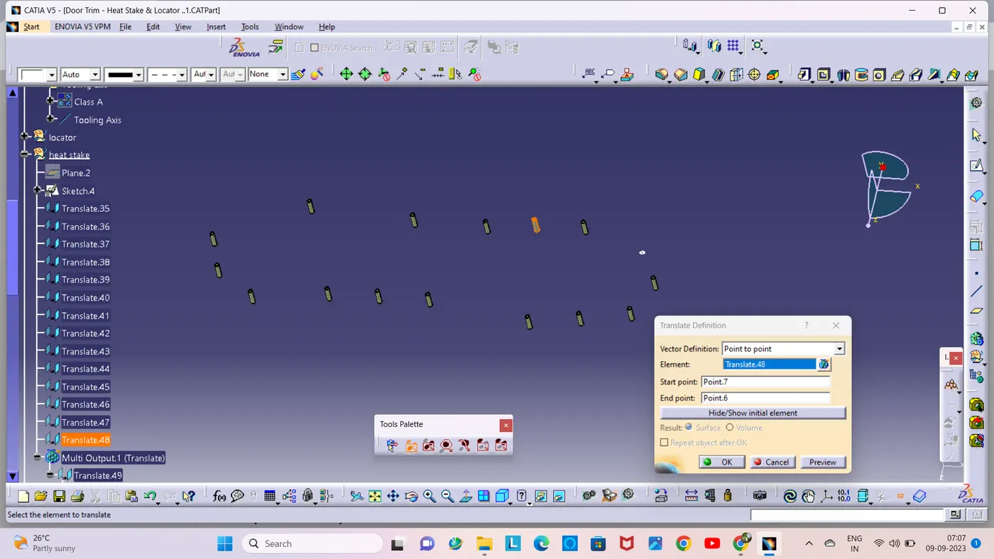
Then i created the heat stakes at the given points using the translate command.
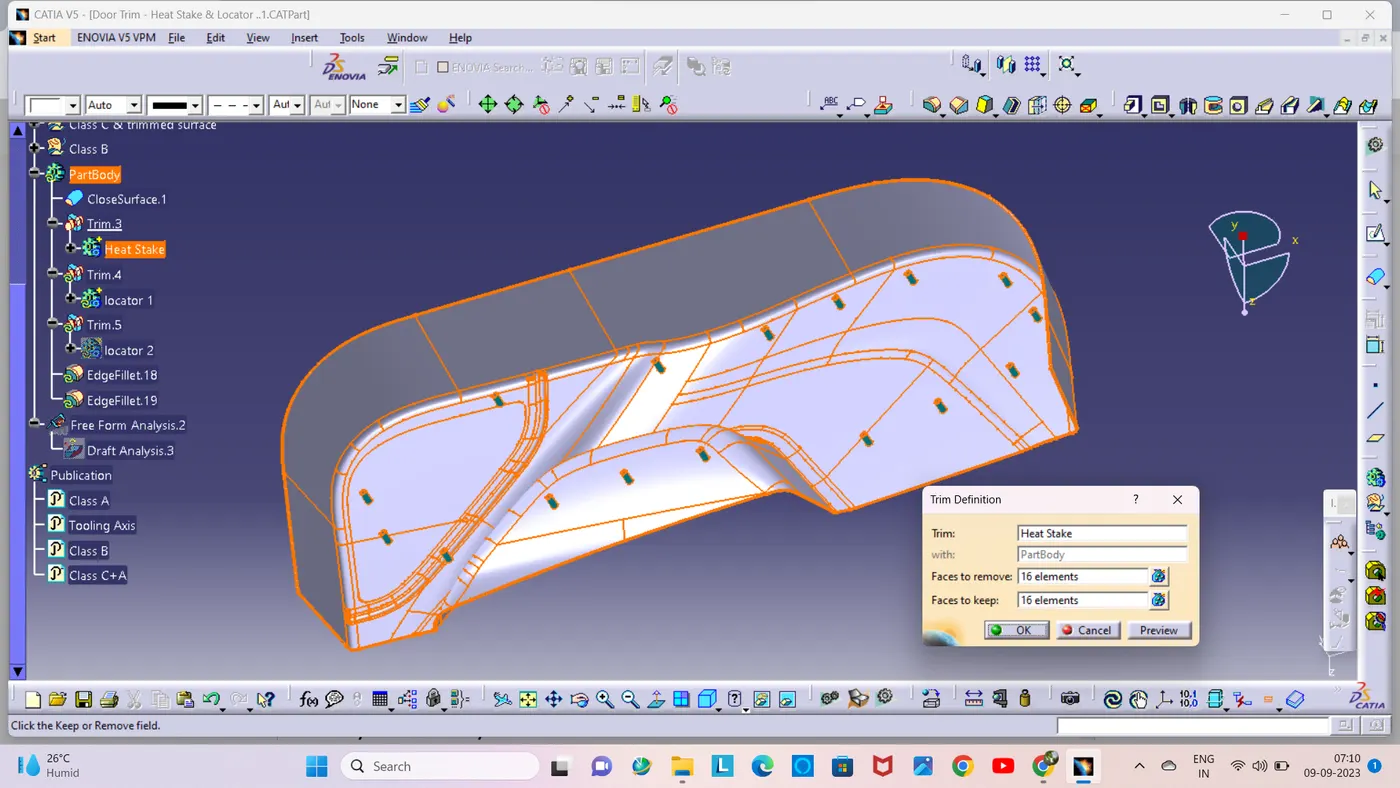
After creating the heat stakes and locators are attached to the solid model using the union trim command.
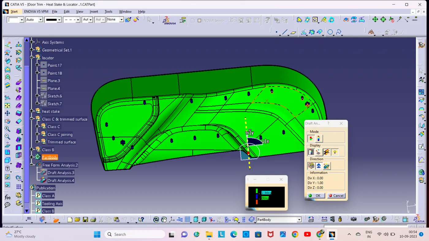
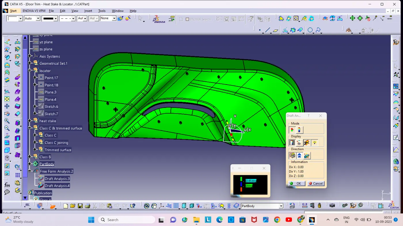
Draft analysis on solid body:
Draft analysis checks at 2.9 degrees.
Draft analysis checks at 0.45 degrees.
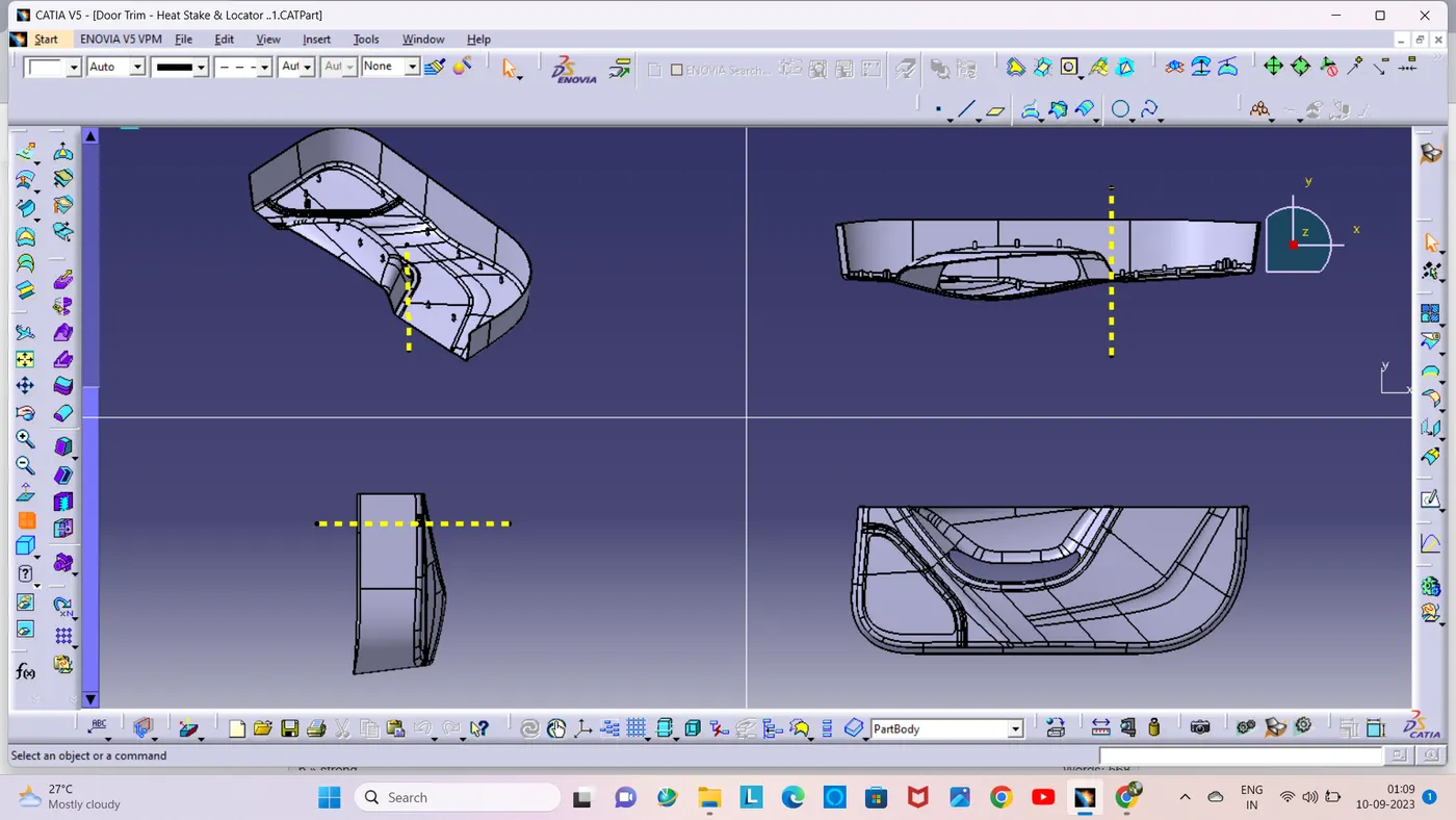
Finally got Door Trim Lower with Engineering Features:
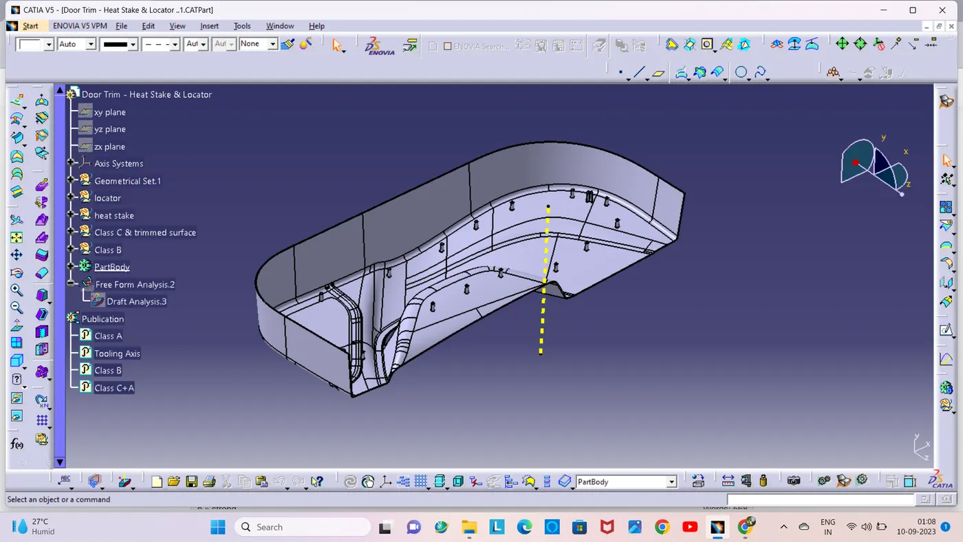
Isemetric,Front,Side and Top view: