Week 10 - Challenge 3 - Door Trim Lower with Engineering Features
Week 10 Challenge
Door Trim Lower with Engineering Features
Aim:
Create the Heat Stakes and the locators for the Door applique considering the design rules.
Steps:
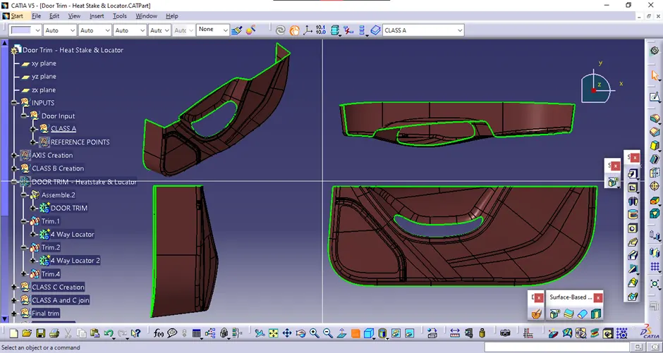
Given Class A:
<!--[endif]-->
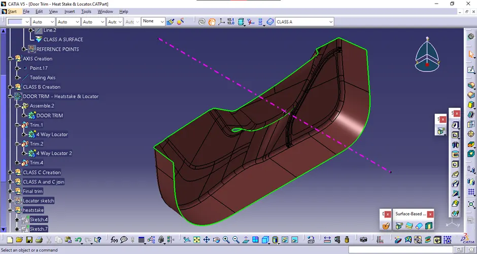
Tooling Axis:
Considering the Ejection from the cavity of the mold after manufacturing the component, it must have a nominal 3-degree draft angle.
The tooling direction is created by considering the above factor. And hence the tooling axis is created along Y-axis.
<!--[endif]-->
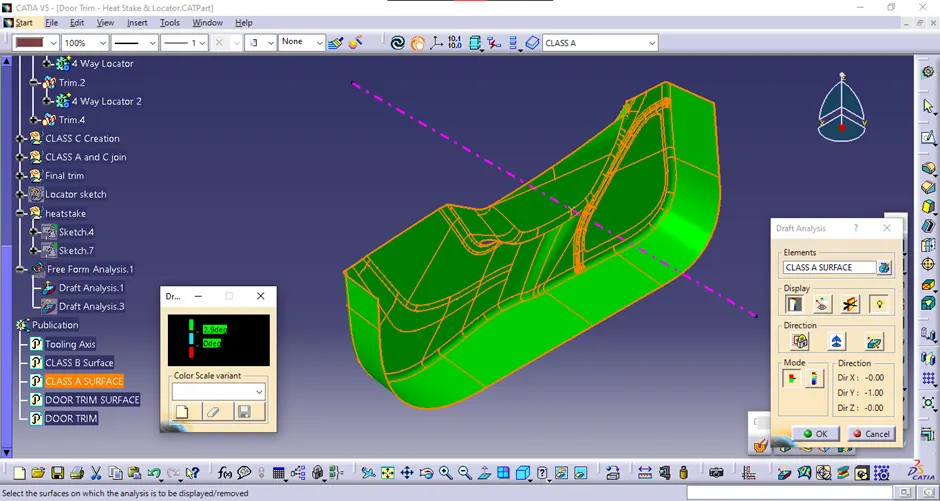
Draft Analysis of Class A:
To make the red zones into green, positive draft side draft angle was decreased from 3 to 2.9 degrees.
<!--[endif]-->
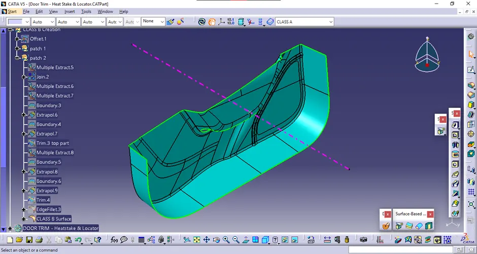
CREATION OF CLASS B SURFACE:
Class B surface has been created by offsetting the Class A surface.
There were some fillet errors while creating offset. Those errors were corrected by extracting and creating separate fillets.
<!--[endif]-->
CREATION OF CLASS C SURFACE
The required outer edges of the A-Surface were extracted using Multiple Extract.
Then by using the sweep command the Class C surface was created with appropriate draft angle.
Then, using extrapolate command, the edges were intersected between the surface corners, which eases the trimming operation.
Now the required portion of the C – the surface was trimmed out.
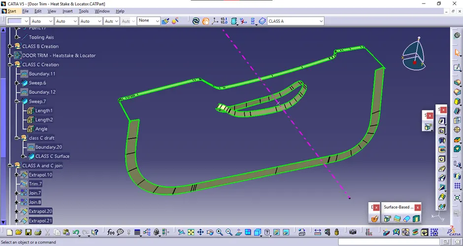 <!--[endif]-->
CREATION OF CLOSED SURFACE
Now the class – A and Class- C surfaces were joined together by removing the gaps in between.
Then the exact surface of the Bumper was trimmed from the above-resulted trim surface with the class-B surface.
Then, by using the Closed Surface command in Part Design, the component's solid body is created.
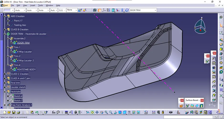
<!--[endif]-->
Draft analysis of Door applique:
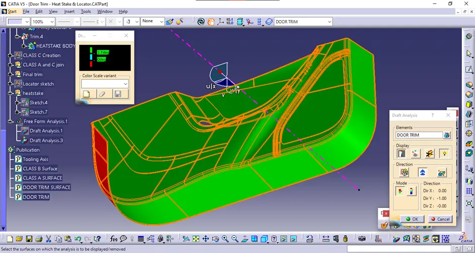
<!--[endif]-->
4-Way Locator
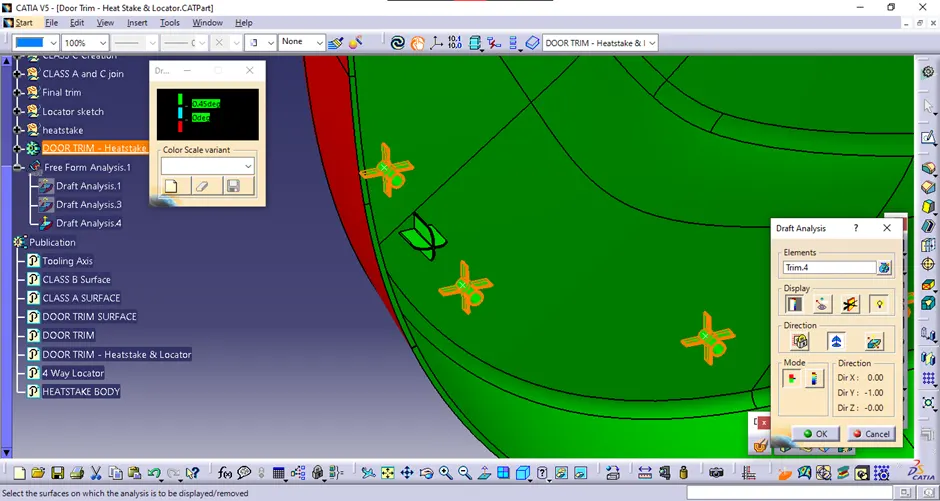
A 4-way locator was created using pad and chamfer in the direction of tooling axis. Also, a fillet was also provided. A copy of the locator was made and translated using point-point translation.
<!--[endif]-->
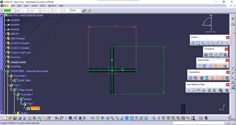
<!--[endif]-->
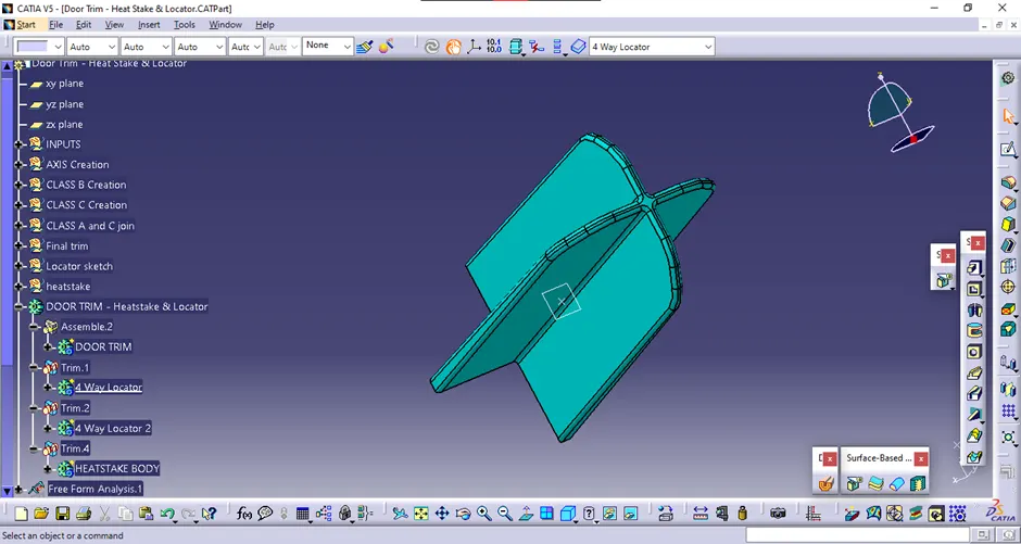
Draft analysis of 4-Way Locator
<!--[endif]-->
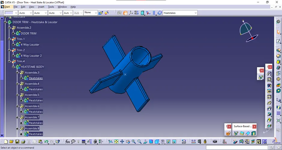
Heatstake
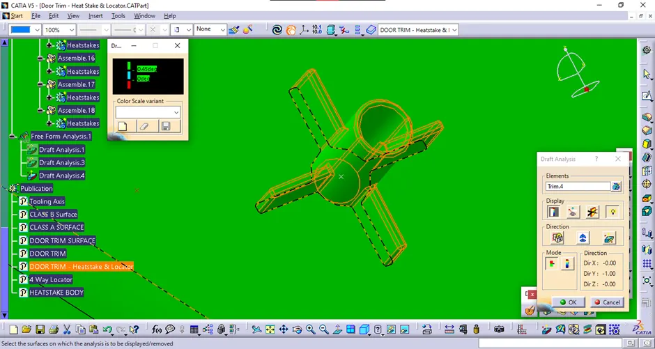
Heatstake was created by using pad and union trim. Ribs were also created to strengthen it. Draft values and fillets were given to the heatstake. And the, it was translated to each given points.
<!--[endif]-->
Draft analysis of heatstake
<!--[endif]-->
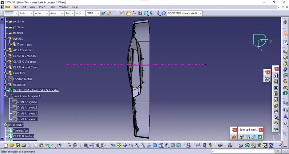
Draft analysis of Final Component:
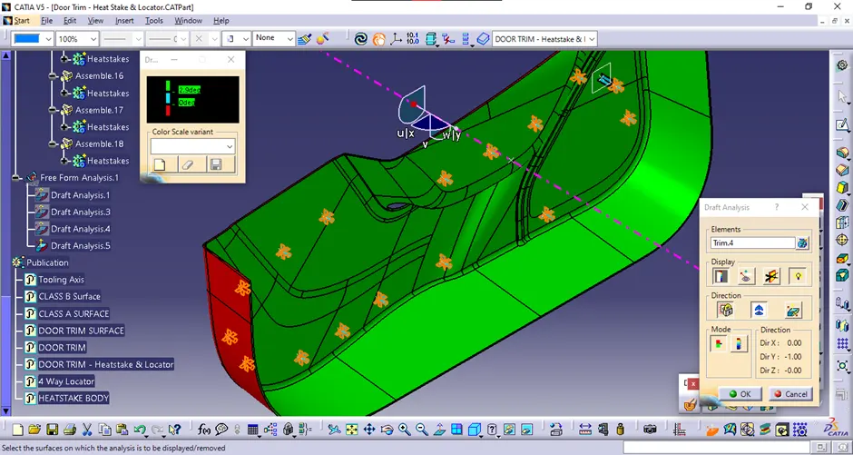
<!--[endif]-->
Screenshots:
Isometric View
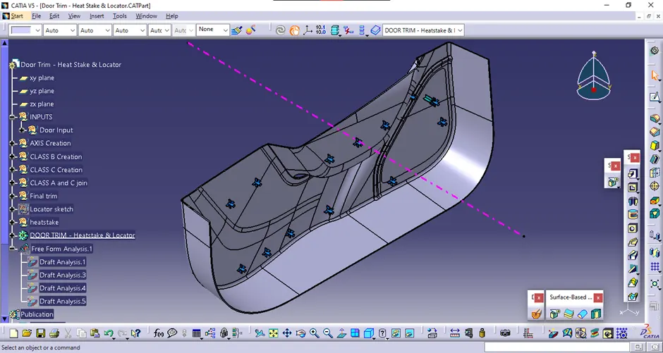
<!--[endif]-->
Front View
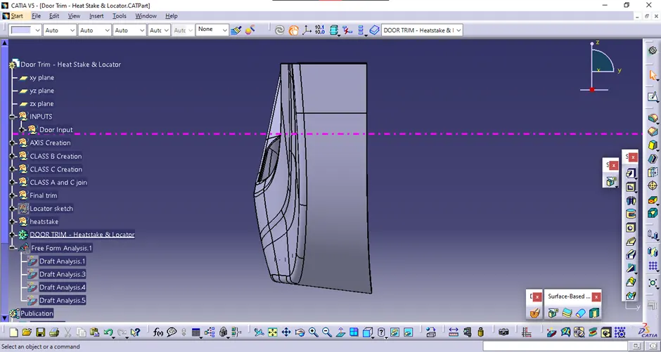
<!--[endif]-->
Right View
<!--[endif]-->
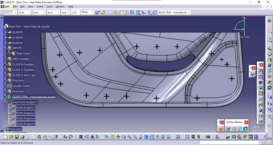
Top View
<!--[endif]-->