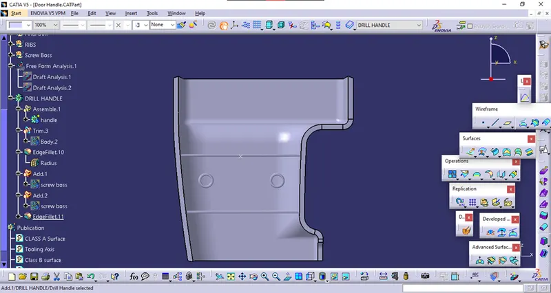
Week 10 - Challenge 1- Attachment Feature Creation (Ribs & Screw Boss)
Week 10 Challenge
Ribs & Screw Boss
Aim:
Create the rib and screw boss for the Drill Handle considering the design rules.
Steps:
Given Class A:
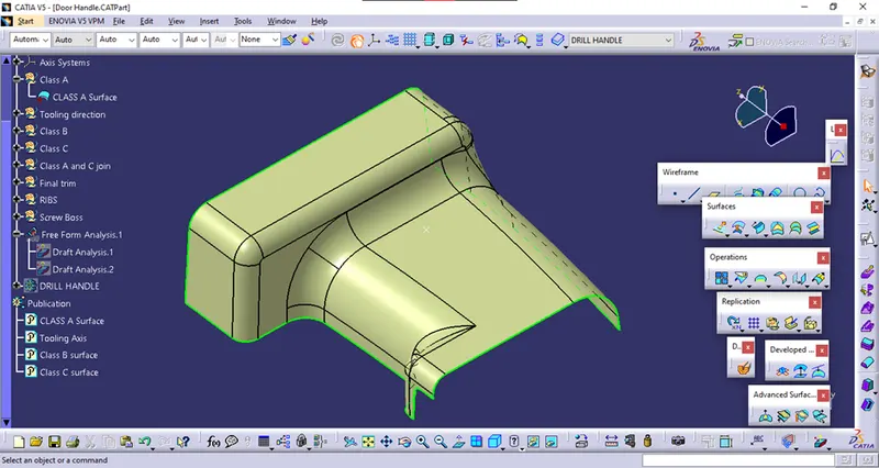
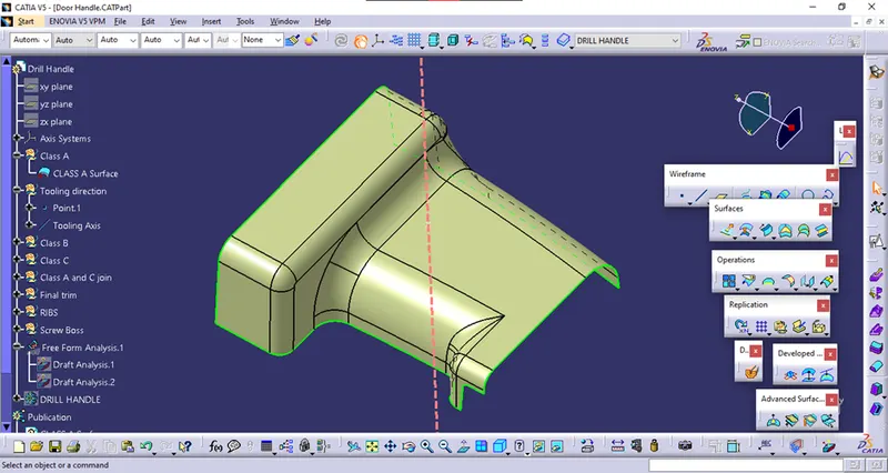
Tooling Axis:
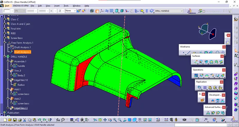
Considering the Ejection from the cavity of the mold after manufacturing the component, it must have a nominal 3-degree draft angle.
The tooling direction is created by considering the above factor. And hence the tooling axis is created along Y-axis.
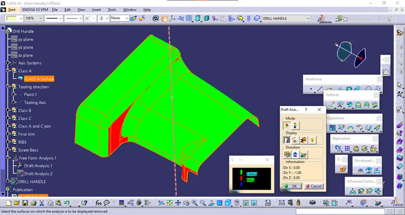
Draft Analysis of Class A:
To make the red zones into green, positive draft side draft angle was decreased from 3 to 2.8 degrees.
CREATION OF CLASS B SURFACE:
Class B surface has been created by offsetting the Class A surface.
There were some fillet errors while creating offset. Those errors were corrected by extracting and creating separate fillets.
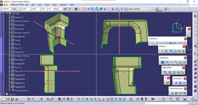
CREATION OF CLASS C SURFACE
The required outer edges of the A-Surface were extracted using Multiple Extract.
Then by using the sweep command the Class C surface was created.
Then, using extrapolate command, the edges were intersected between the surface corners, which eases the trimming operation.
Now the required portion of the C – the surface was trimmed out.
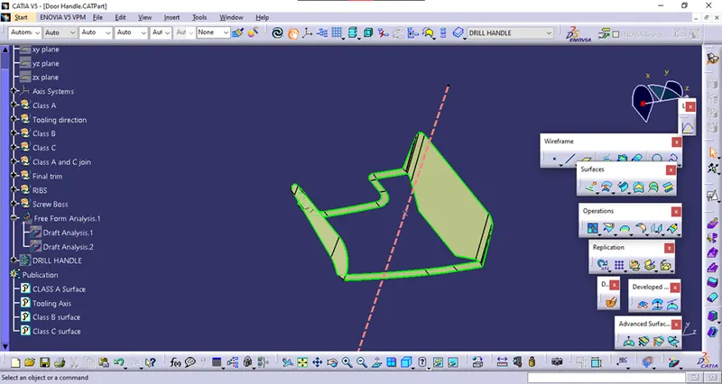
CREATION OF CLOSED SURFACE
Now the class – A and Class- C surfaces were joined together by removing the gaps in between.
Then the exact surface of the Bumper was trimmed from the above-resulted trim surface with the class-B surface.
Then, by defining the part body by using the Closed Surface command in Part Design, the component's solid body is created.
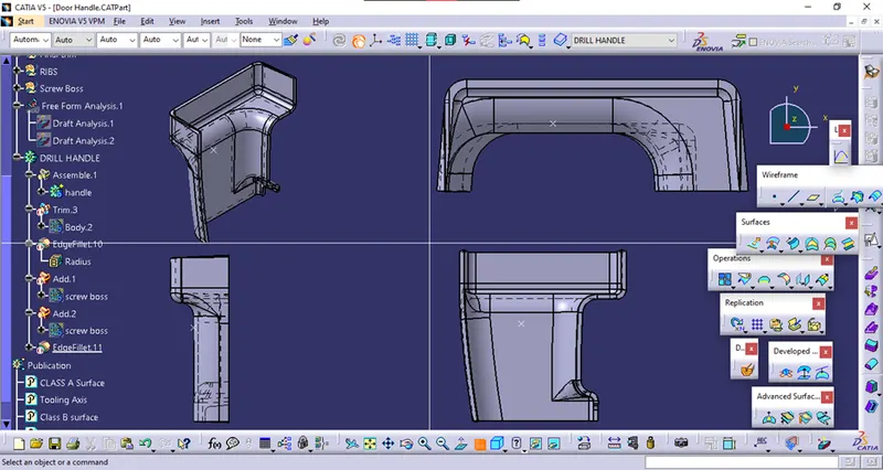
Draft analysis of Drill Handle:
Rib and Screwboss:
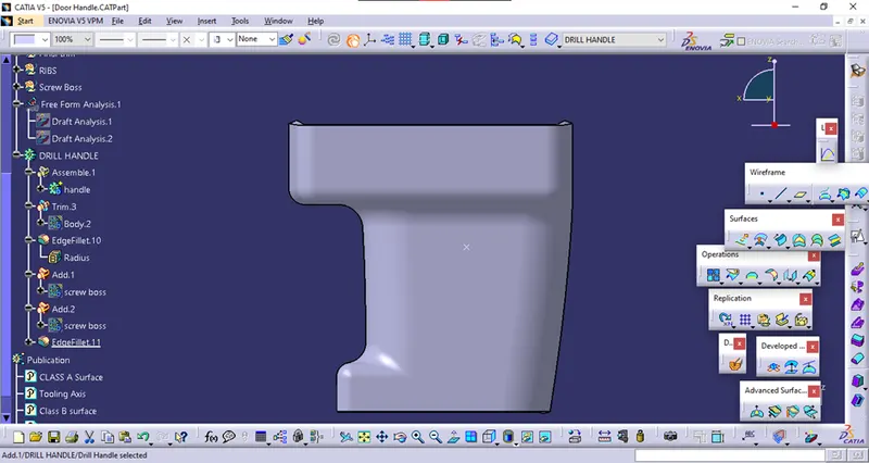
Ribs and screwbosses were created using the guidelines given.
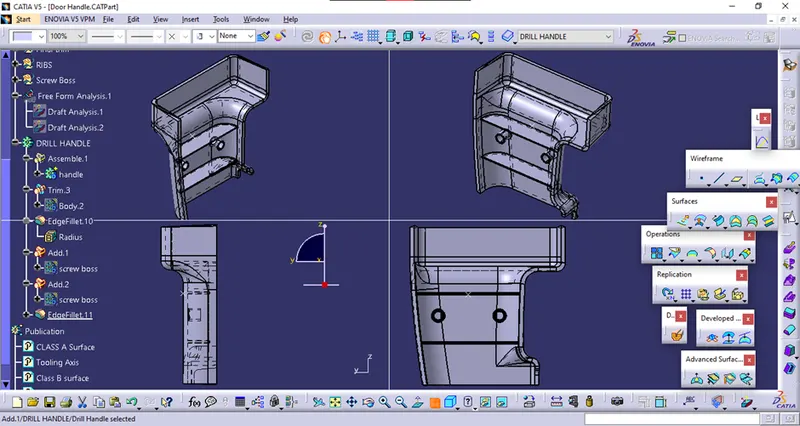
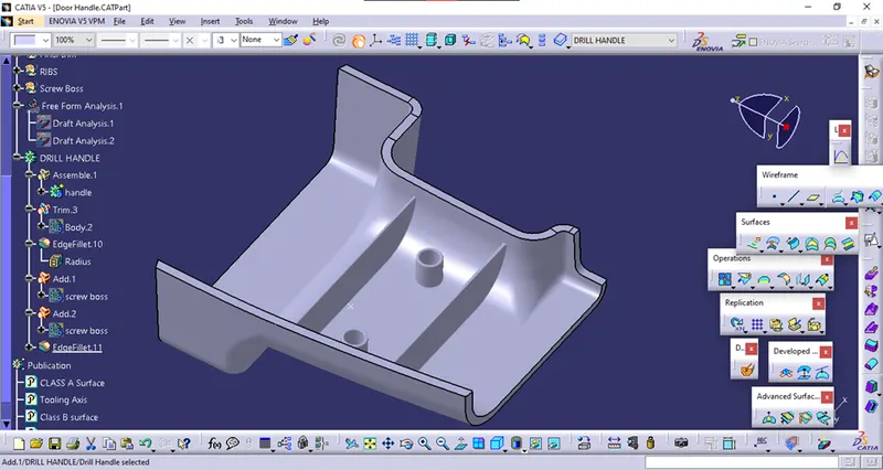
Screenshots:
Isometric View
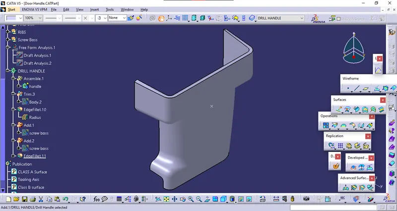
Front View
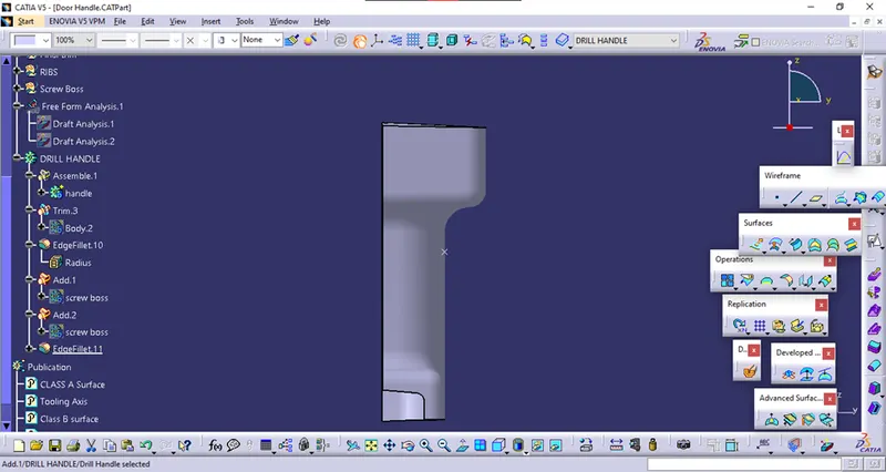
Right View
Left View