Week 10 - Challenge 3 - Door Trim Lower with Engineering Features
WEEK 10 - CHALLENGE 3 = DOOR APPLIQUE
AIM = Create the Door Trim Lower Plastic component through the given Class-A surface. Create the Heat Stakes and the locators considering the design rules mentioned in the video for the door applique and perform Draft analysis.
REPORT
- To create Door trim lower with engineering features was the objective like locators, heat stakes as per design rules for Door Applique and to perform Draft Analysis.
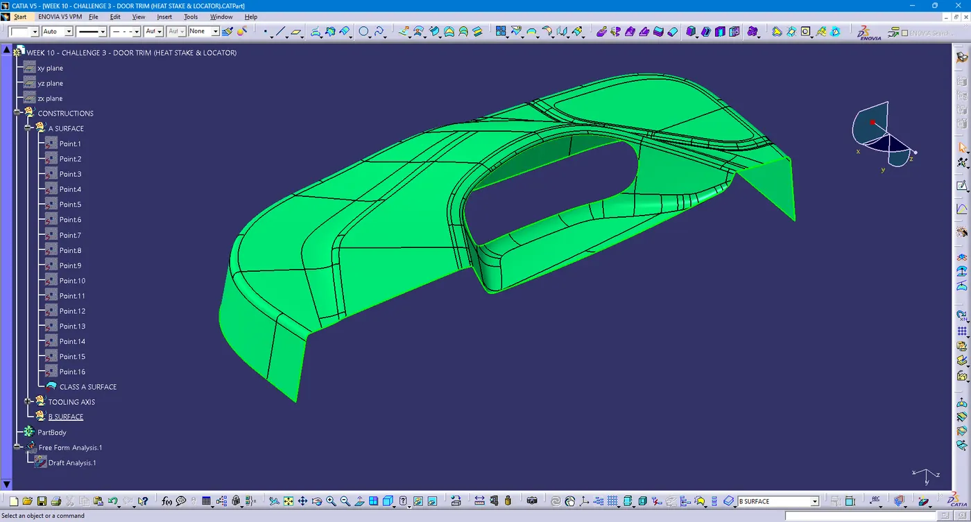
- As similar, Class A Surface is given with detailed location points for heat stakes.
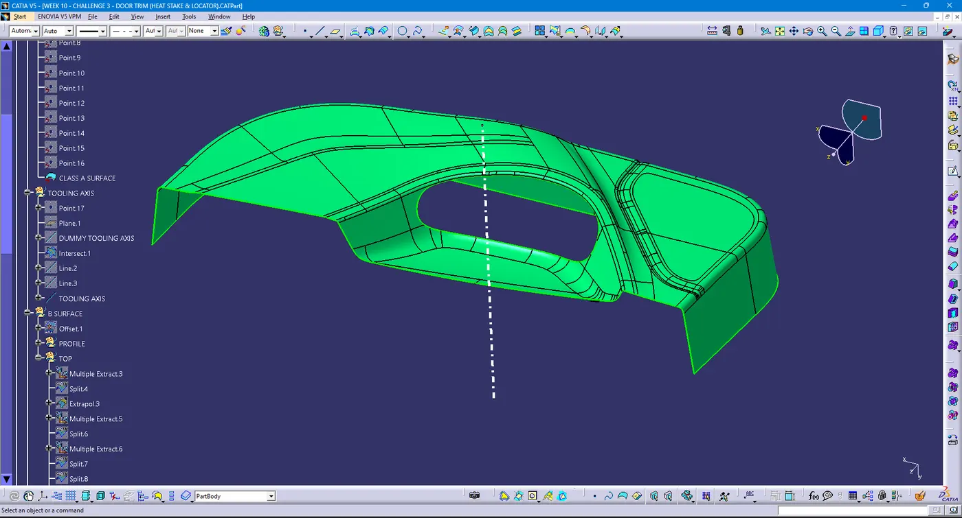
- Tooling Axis is created through Bisecting method as mandated in question using Intersection, plane, line commands. Class A and Tooling Axis are subjected to publication.
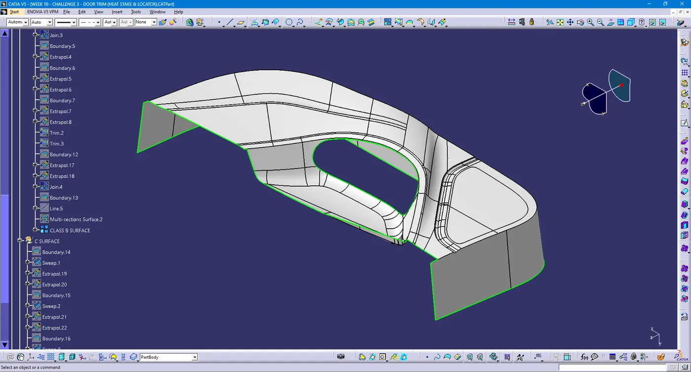
- Class B surface creation has initiated. The given Class A has been offsetted to 2.5mm inward to maintain its wall thickness. Minor substrates are absent in the offsetted surface and is defined to complete the part by differenting it into Profile, Top (as mentioned in tree structure).
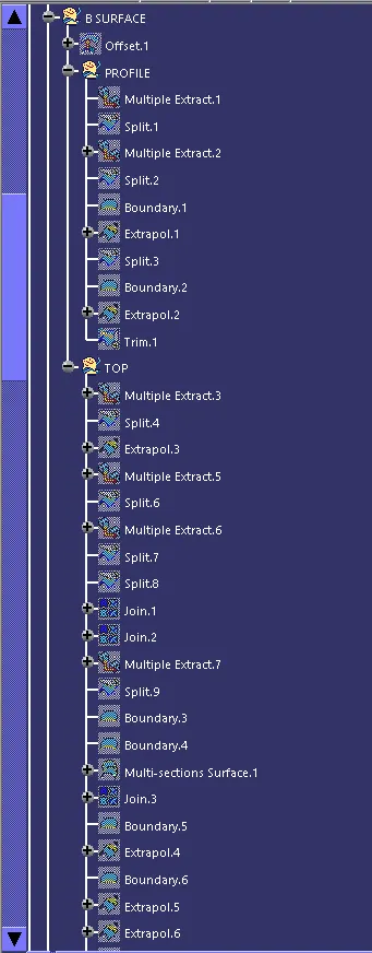
- Multiple Extract, Extract, Split, Extrapolation, Trim, Join with sub-elements to remove, line, Multi surface section, Boundary are used in creation of Class B surface and finally edge fillet command is used to speculate Class B.
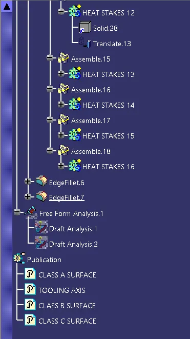
- Class B is published in the workbench.
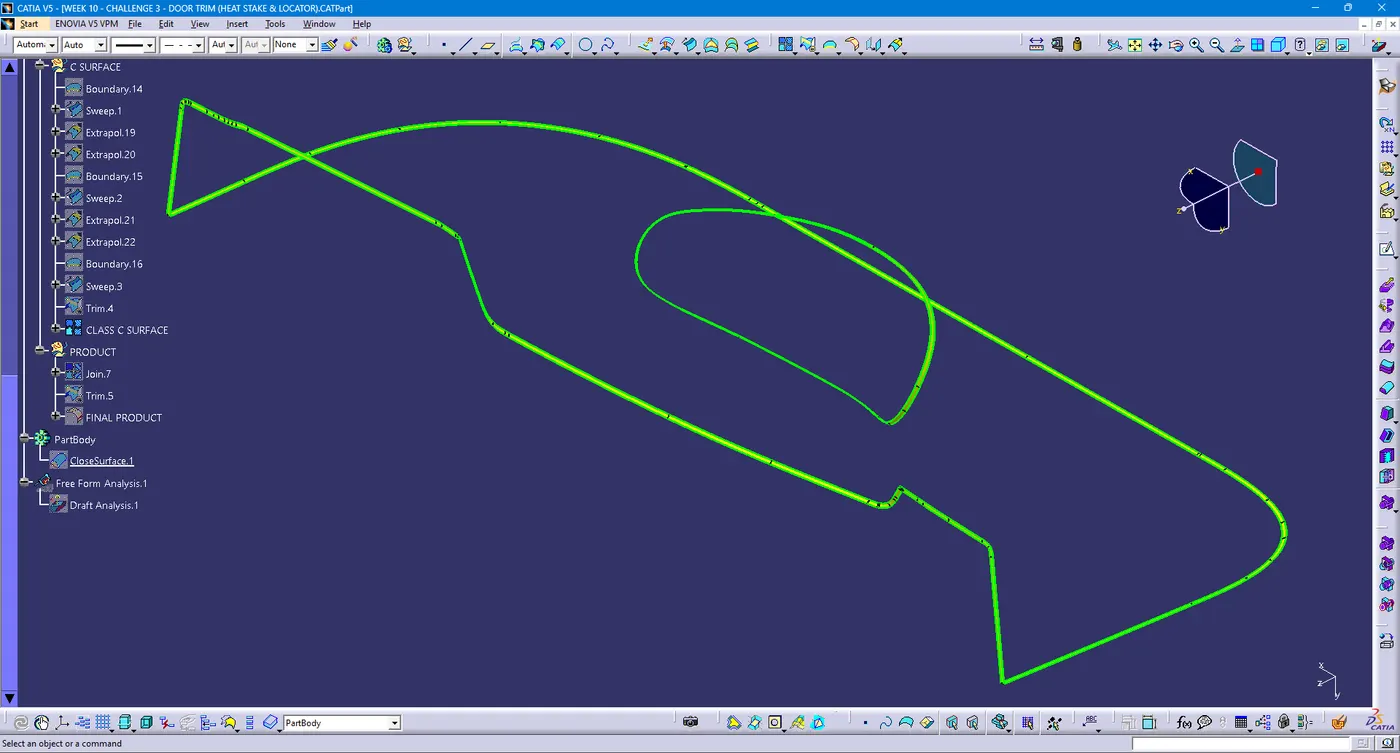
- Initiated Class C creation with help of Class A surface in which Boundary, Sweep, extraplation, trim, join commands are used.
- Then it is subjected to Class A and C join followed by final trim with Class B to generate the final product.
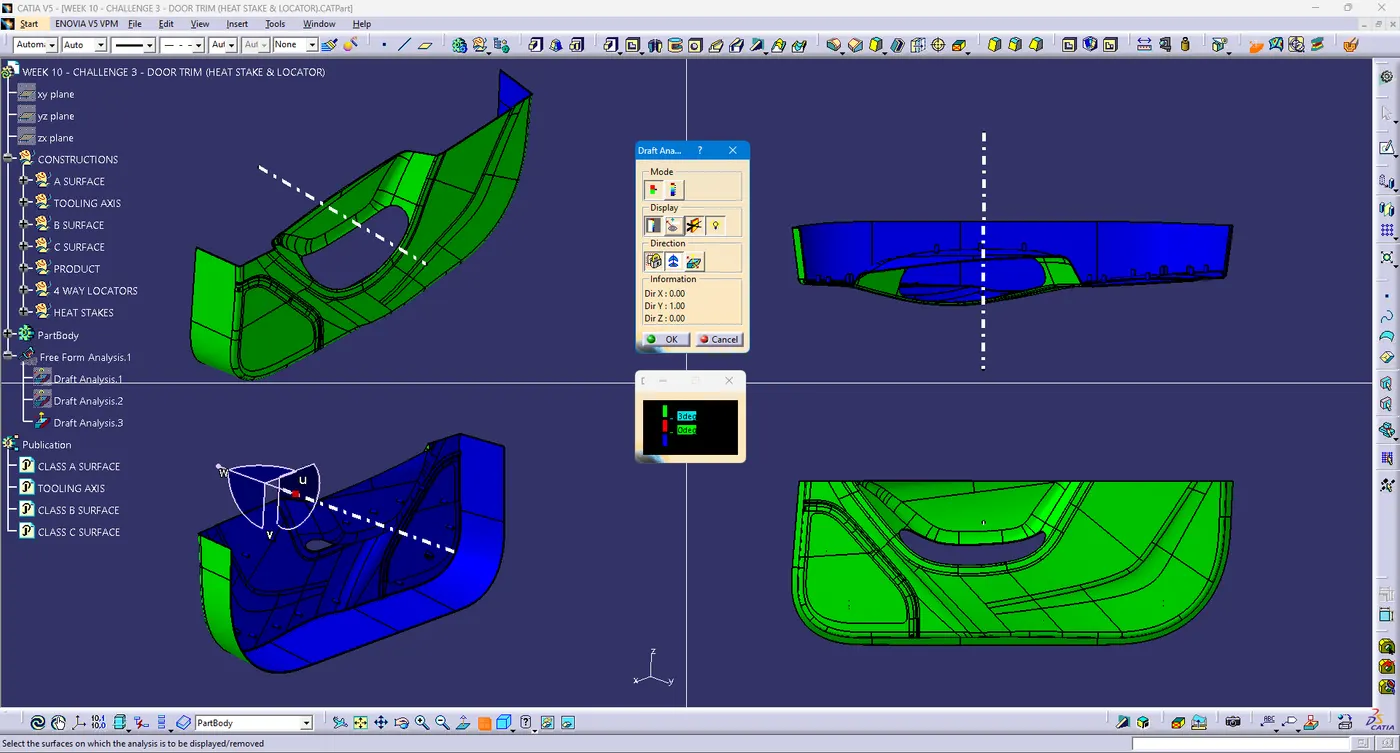
- Class C is published and Final product is subjected to draft analysis and is cleared with 3 deg draft.
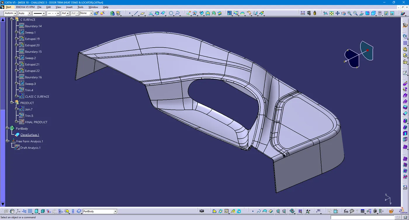
- Final partbody is featured with close surface.
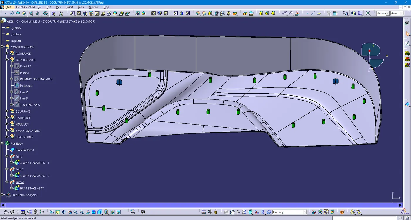
- Started the creation of engineering features like locators and heat stakes mandated in the question.
- Position sketch is selected for the base drawing of locators, created it with
- 15 x 15 mm in cross over direction,
- Pad it for 20 mm,
- 0.5 deg min. draft,
- 3mm chamfer with 45deg on the edges of locators,
- fillet of 3mm on top curvature and 0.3 mm for locator leafs.
- Second locator is created through translation method and both are performed with union trim operation to being part of the partbody.
- Heat stakes are also created with position sketch;
- Dia. of 5mm and 7 mm
- Height of 17 mm
- 0.5 deg min. draft,
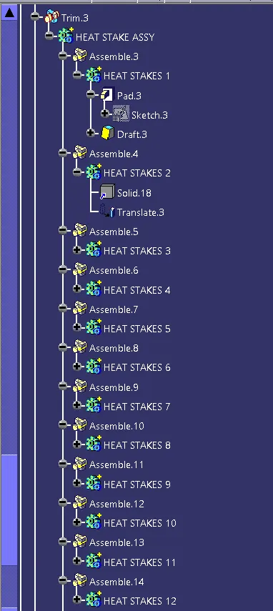
- Done the translation operation to another 15 locations as per given inputs. Suppossed to union trim to join it too with partbody and are provided in Heat stake assy body.
- Final fillets are provided to the base of locators and heat stakes as 0.25mm.
- Detailed screenshots, drawings and tree structure is attatched below for reference.
IMAGES
- CLASS A SURFACE
- TOOLING AXIS
- CLASS B SURFACE
- CLASS C SURFACE
- FINAL PRODUCT
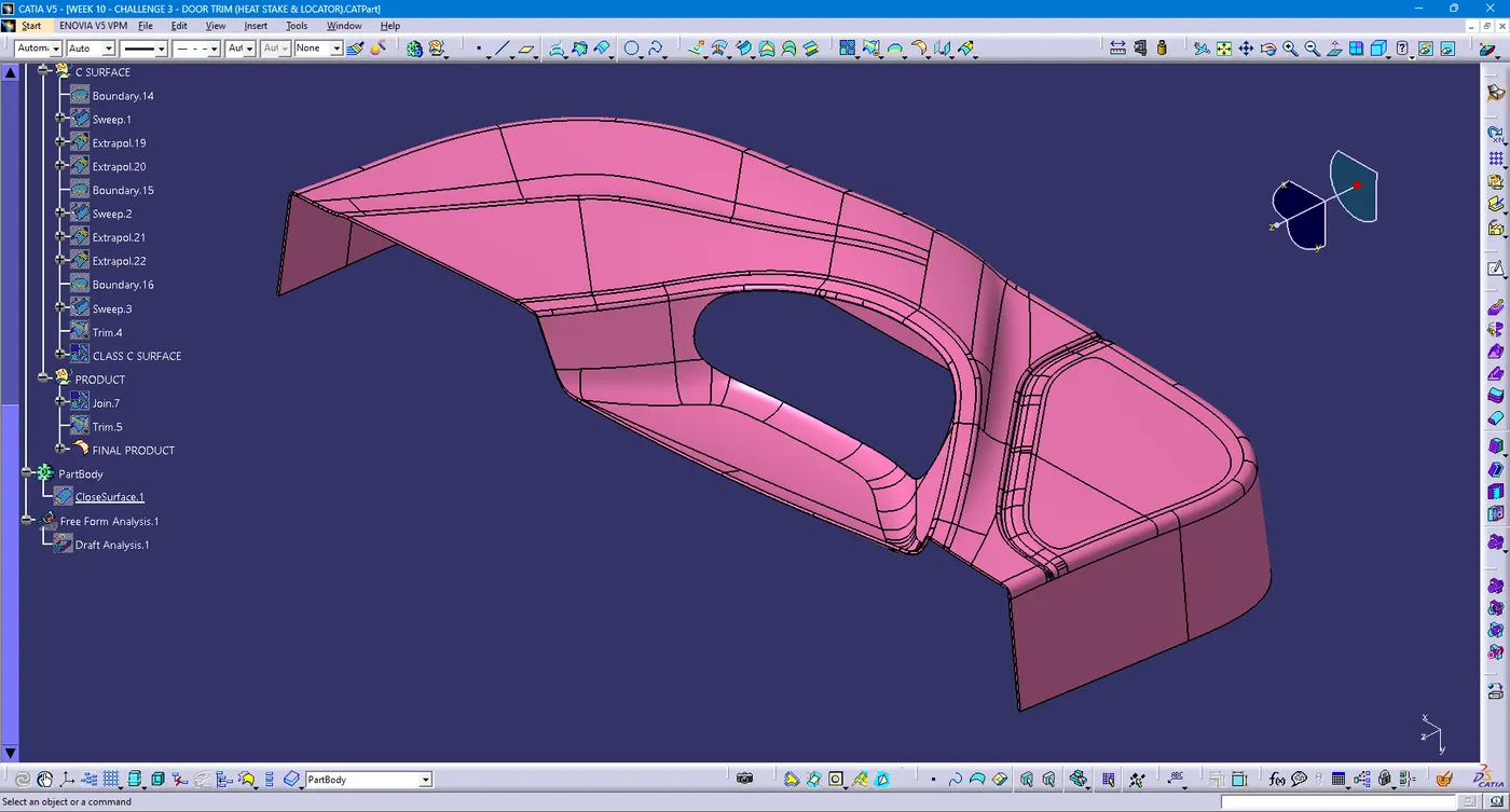
- DEFINED PARTBODY
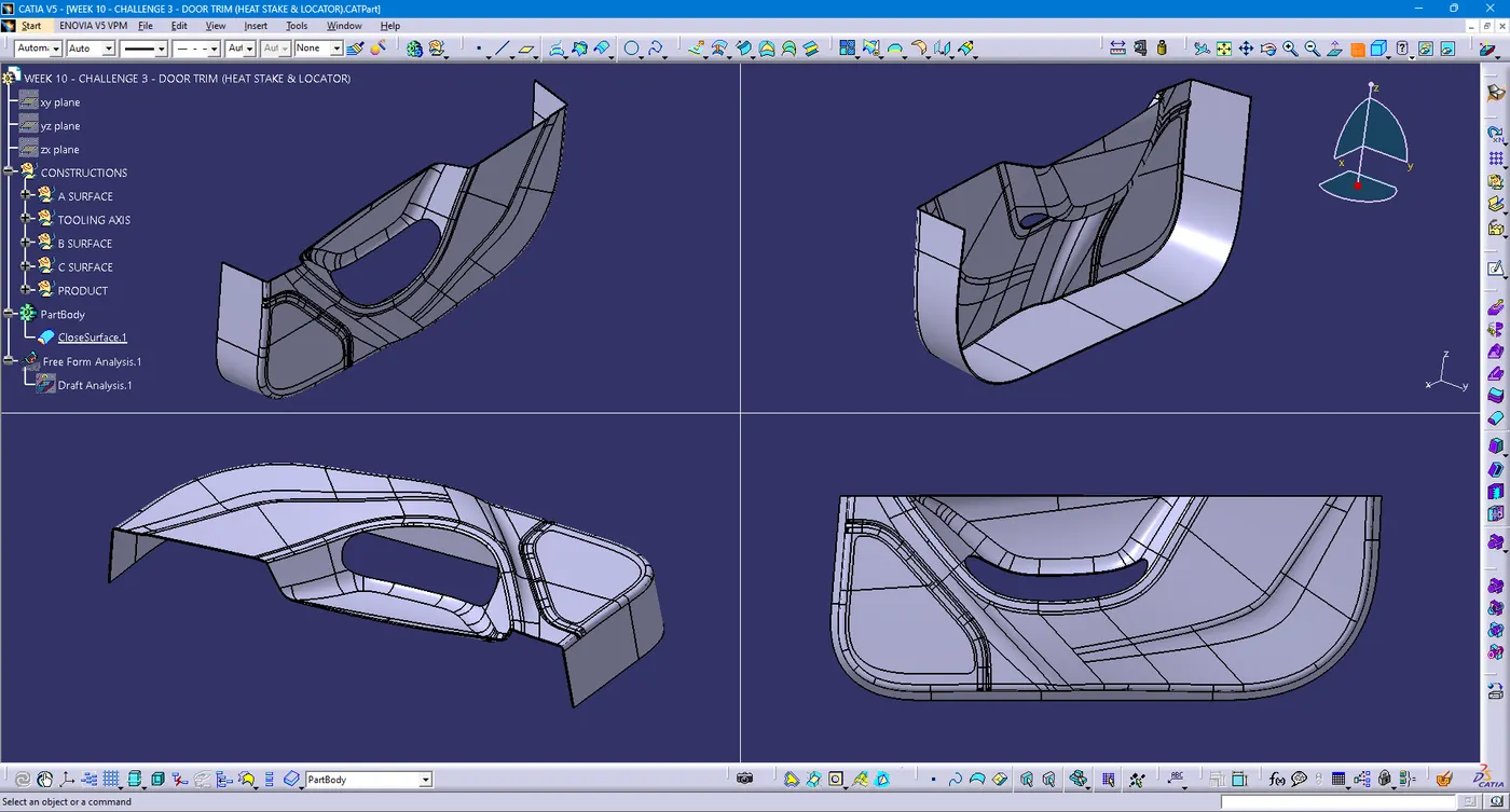
- DIFFERENTIATED VIEWS
- LOCATORS AND HEAT STAKES
- DRAFT ANALYSIS OF CLASS A SURFACE
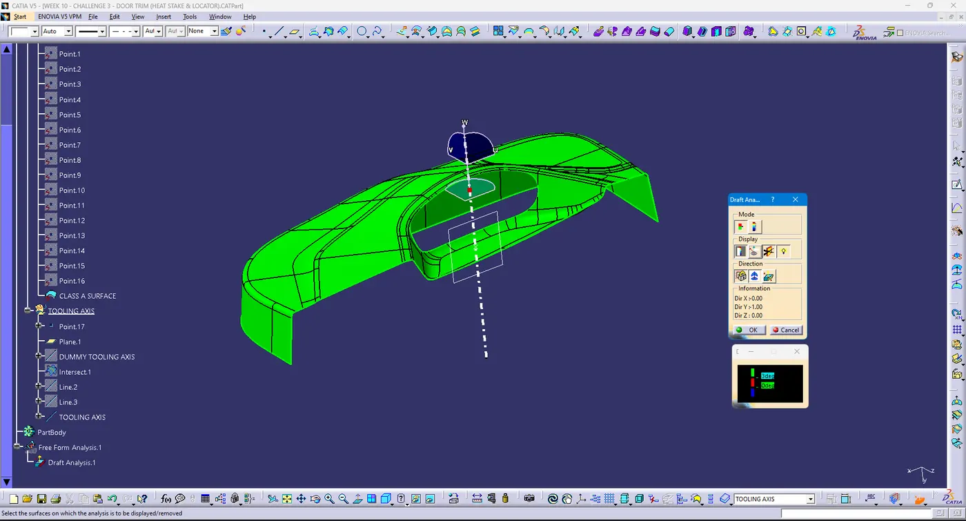
- DRAFT ANALYSIS OF FINAL PRODUCT
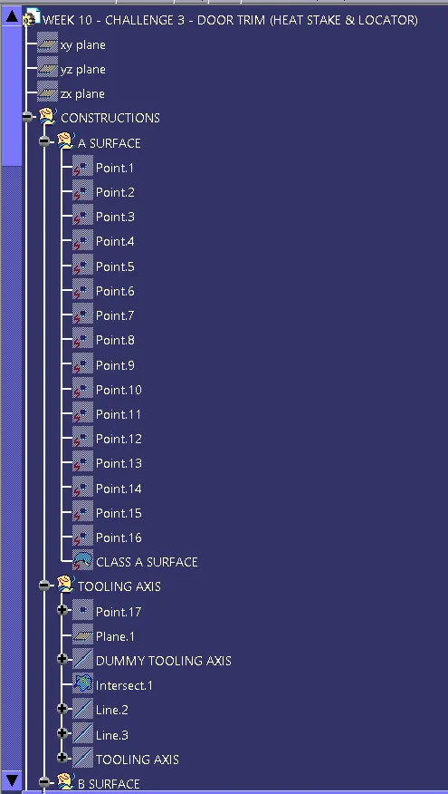
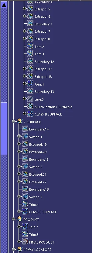
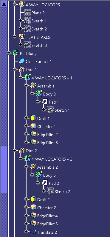
- DETAILED TREE STRUCTURE
NOTE:
- Positioned sketches are used and are Iso-Constrained
- Given model is used as reference to create the locators and Heat stakes
- Proper Tree Structure is maintained
- Geometrical sets are properly named based on the sketches present inside and all sketches are created under geometrical set.
- Tooling axis is created using Bisecting method
- Draft analysis is done properly.