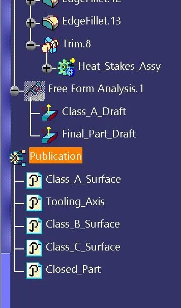
Week 10 - Challenge 3 - Door Trim Lower with Engineering Features
Aim:
Create the Door Trim Lower Plastic component through the given Class-A surface. To begin with, the tooling axis for the given Class-A Surface should be created meeting the requirements of the draft angle and at the end perform the Draft analysis on the model.
Create the Heat Stakes and the locators considering the design rules mentioned in the video for the door applique.
Door Trim Lower:
Class_A_Surface:
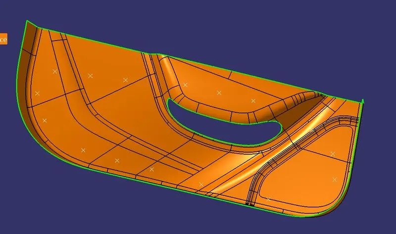
The above A_Surface is the source part for creating the B and C surface of the Door Trim.
Tooling Axis:
To create the tooling axis first we have to check the best suitable direction for tooling by using the compass. The Y direction is suitable for creating the tolling axis because in the Y direction most of the surfaces are clearing while performing draft analysis.
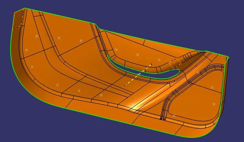
Draft analysis of Class- A
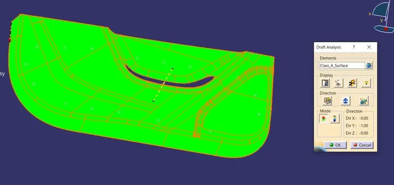
After creating a tooling axis we do the draft analysis. Before drafting we have to make sure that in the view mode it is selected for the materials.
After selecting the feature draft analysis tool we drag the compass from its position to the tool axis. Then lock the compass. After that select anywhere on the component and it will give you the result.
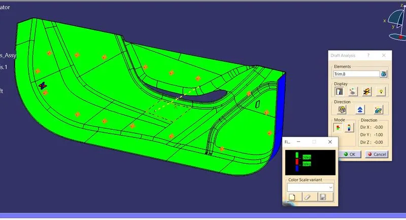
We change the minimum draft for the component to 3°.
Class_B_Surface:
In this part we are going to use the another method for B_Surface creation, for this we can offset the A_Surface directly to the outward direction. After offseting we have some errors on the B_Surface. Because some fillet patches are not offset perfectly, they'll make incomplete surface gaps. So we want to create the near surfaces for getting the final B_Surface for the plastic component surface creation.
Offset_B_Surface:
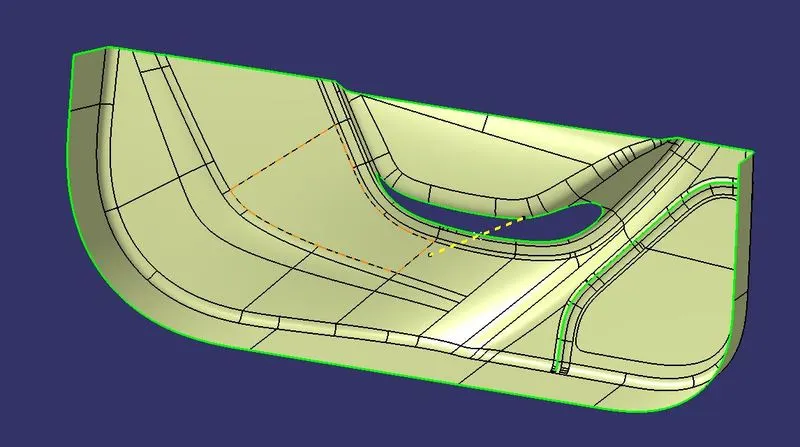
We can see some errors on this surface for the B_Surface creation, after completing all the patwork done on this surface we can get the final_B_Surface.
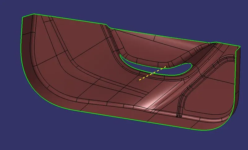
Class_C_Surface:
In this we are going to use the A_Surface edge boundaries to create the C_Surface for the by using the sweep tool. In that sweep we'll use the draft direction to 3deg, and also using the reference surface to create the C_Surface.
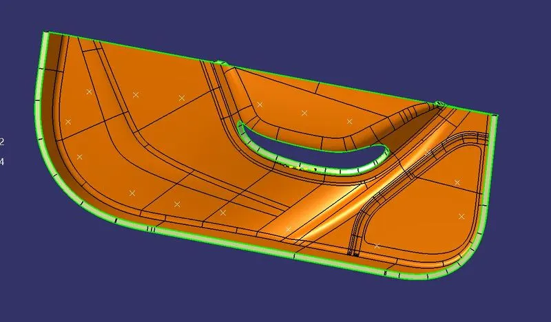
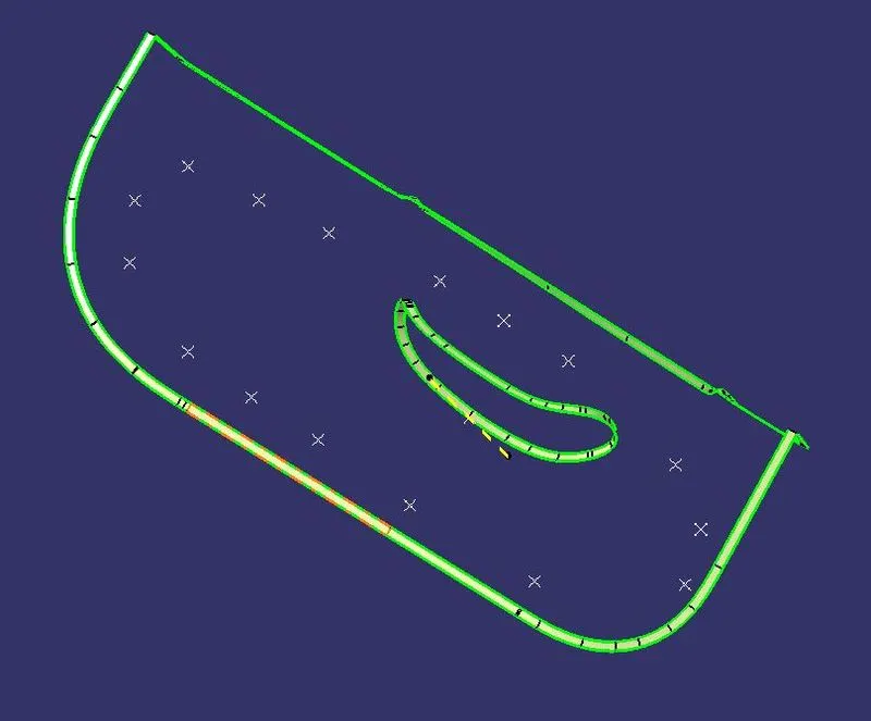
Then we are going to join the A_Surface and the C_Surface, later we'll get this surface. Then we can trim with the B_Surface, Later we'll get the final part surface.
Final Component Surface:
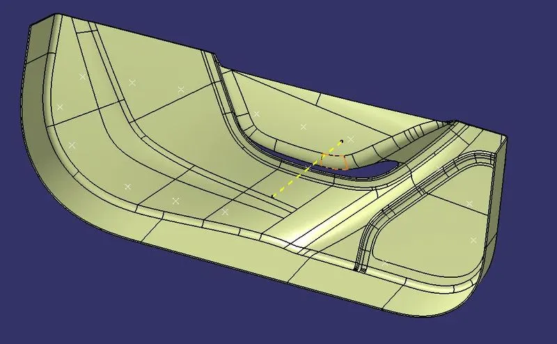
Final Plastic Component:
By using the close surface tool in the part workbench we'll get the final part as solid profile.
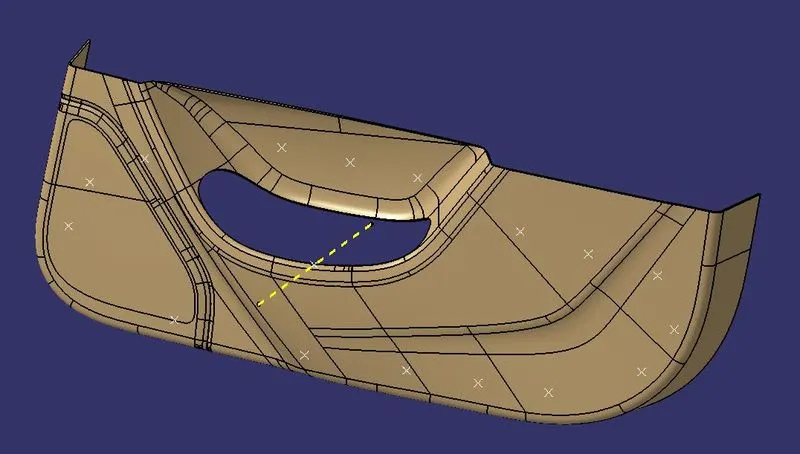
CREATION OF LOCATORS:
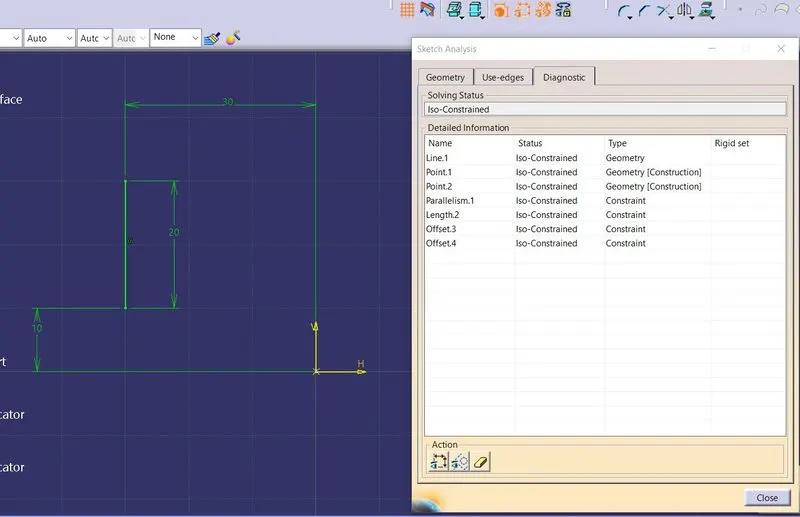
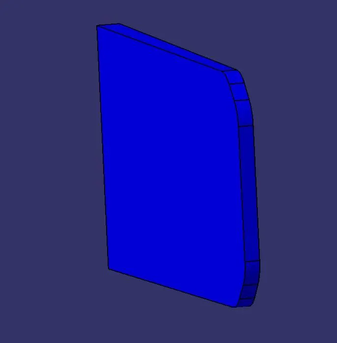
To create the locators, I created a sketch on the body. After creating the sketch, I pad it 15mm in height and thicken it to 1.3mm and I drafted it with 0.5deg in the direction of the tooling axis. I gave 3mm of chamfer with 45deg of inclination and after I gave a fillet of 0.3mm radius.
4-way locator:
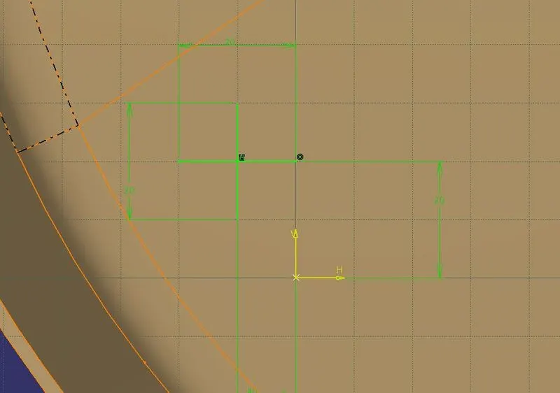
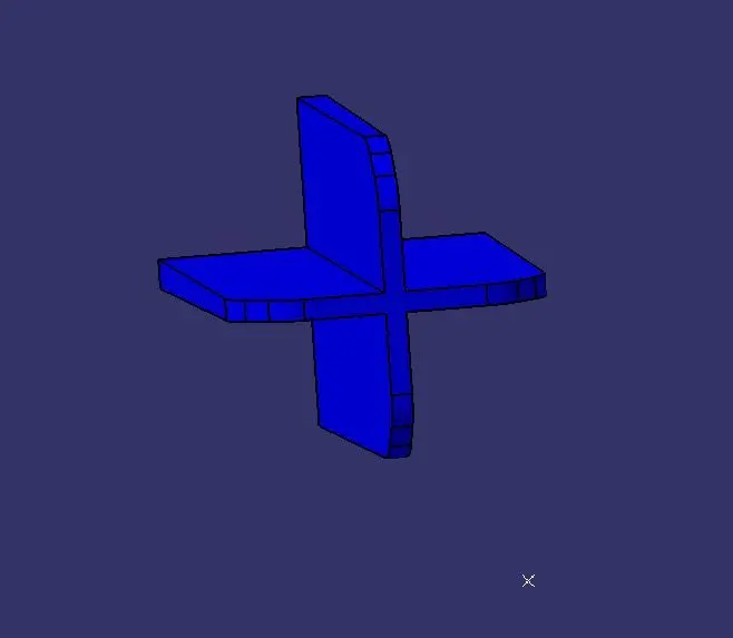
2_Way_Locator:
CREATION OF HEAT STAKES:
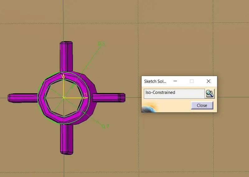
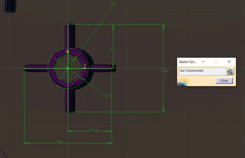
To create the heat stakes, I draw a sketch on the surface. After the creation of the sketch, I pad it to 15mm height and I gave a draft angle of 0.5deg on both sides (inside and outside) and then I gave a fillet with a 0.25mm radius. After creating the heat stake, I created the ribs for supporting purposes. To create the ribs, I draw a sketch and padded it to 10mm in height and 1mm in thickness. After padding the ribs, I drafted 0.5deg in the tooling asix direction and filleted it with a 0.25mm radius. Finally, I union trim the ribs with a heat stake to remove the ribs, which are present inside the heat stakes.
Heat stake sketch:
Rib Support for Heat Stake:
Heat stake with supporting ribs:
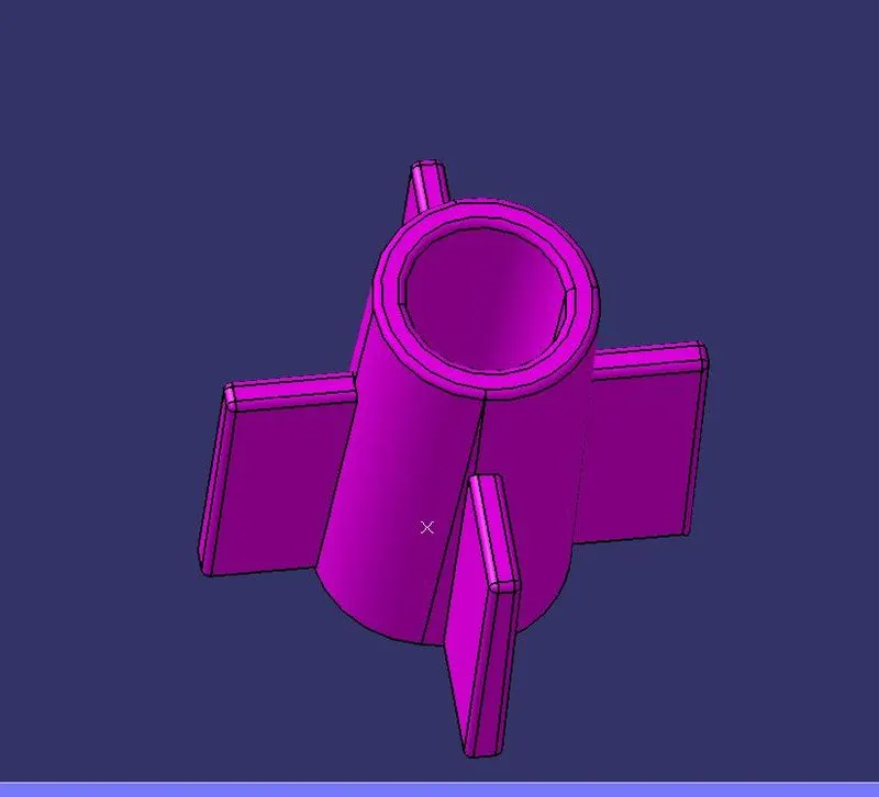
Then I use the user pattern by using the position option to locate these heat stakes to place on this component.
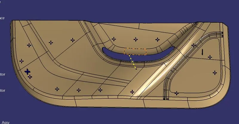
And also use the 4way and 2way locators to place in this by using the boolean operations on it.
Final output part:
Draft Anlysis for the Final Component:
3D_View with various Orientations:
Front View:
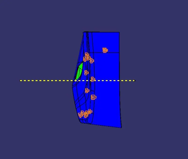
Top View:
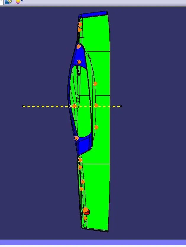
Side View:
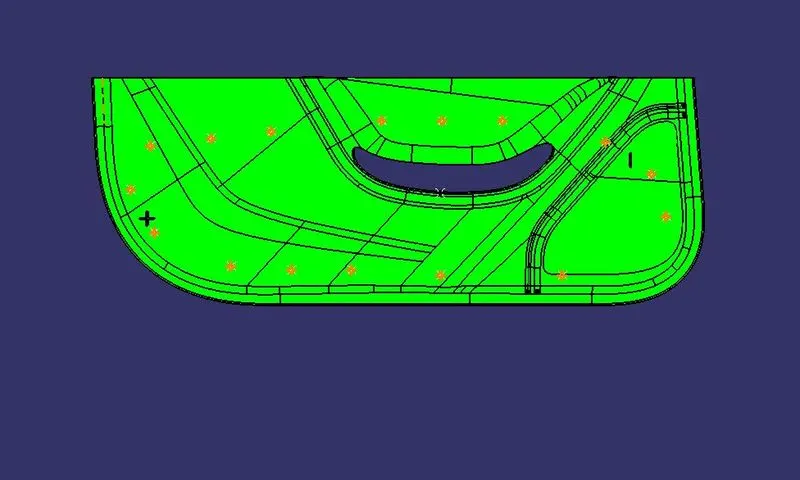
Isometric View:
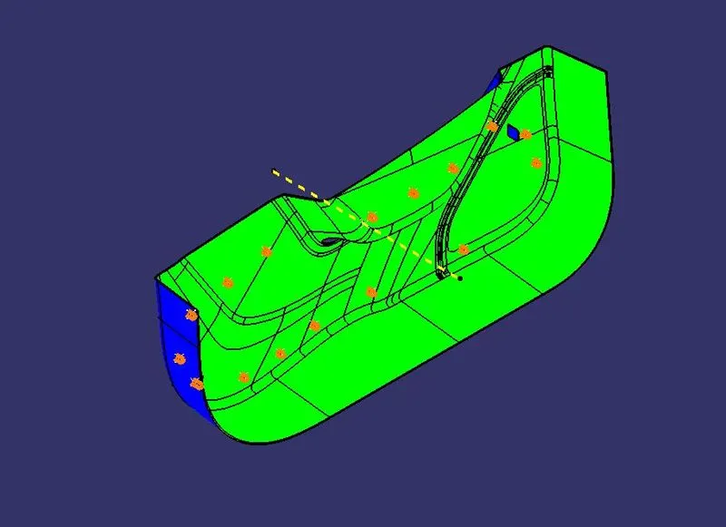
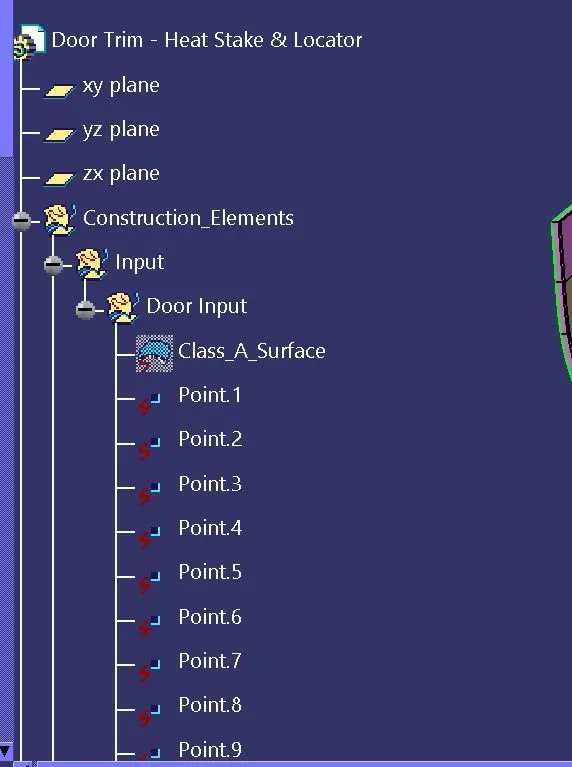
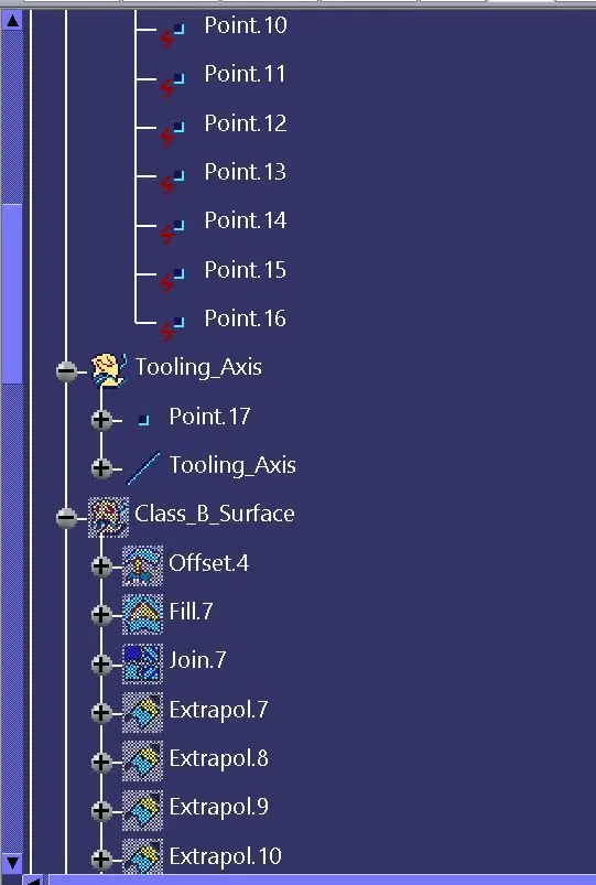
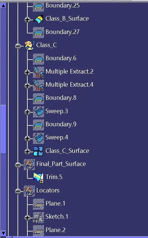
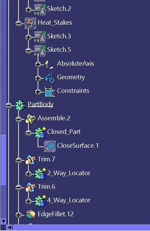
Tree Structure: