Week 10 - Challenge 3 - Door Trim Lower with Engineering Features
AIM:TO Create the Door Trim Lower Plastic component through the given Class-A surface. To begin with, the tooling axis for the given Class-A Surface should be created meeting the requirements of the draft angle and at the end perform the Draft analysis on the model. And to Create the Heat Stakes and the locators considering the design rules mentioned in the video for the door applique.
Requirements
- Sketches
- Use Positioned sketch
- Sketches should be Iso-Constrained
- References
- Use the given points in the model to create the locators and Heat stakes
- Refer to the below-given image for more details
- Tree Structure
- Ensure Proper Tree Structure
- Geometrical sets should have a proper name based on the sketches present inside of it
- All the sketches should be created under the Geometrical set
A reference of the approximate location of the locators
Below is a image of the class A surface
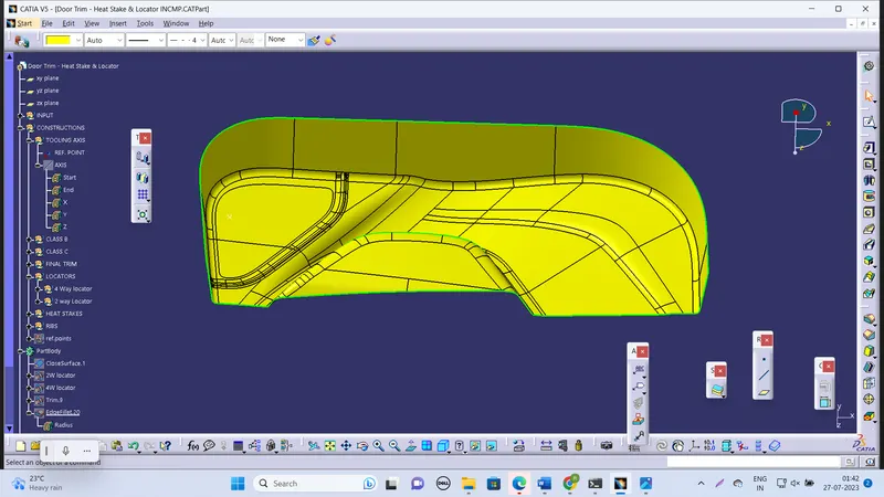
I have created a tooling axis by creating a point on the extract of the flat surface of the given class A and by using point two direction option i've created a line in Y direction because this is the appropriate tooling direction and this could clear the draft
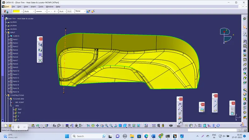
After that I've created the Class B by offsetting the Class A to a distance of 2.5 mm as given after offsetting I have faced many mistakes in the surface so I worked on it to get final B surface
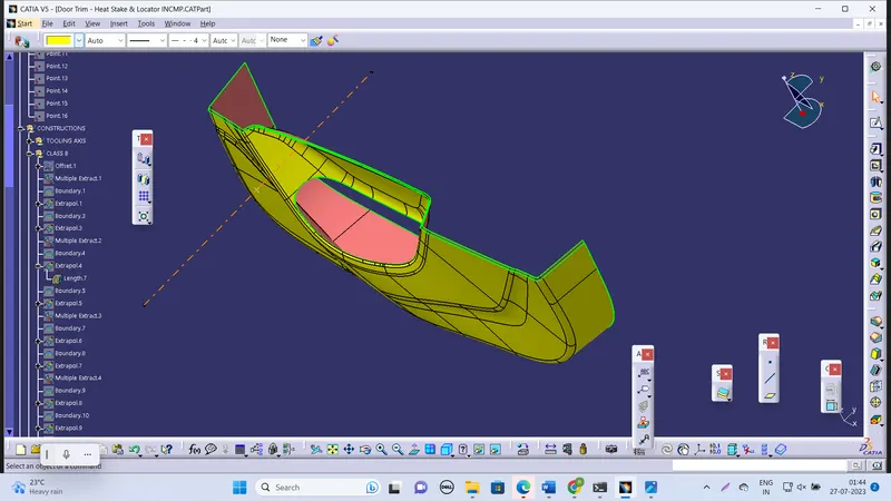
After that I created classy surface by using sweep Here I have given a draft degree of 3 for the sides which require and also with reference to surface I have given 90 degrees.
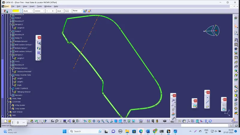
All the surfaces A and B and C are trimmed to get final closed surface which is after made into solid
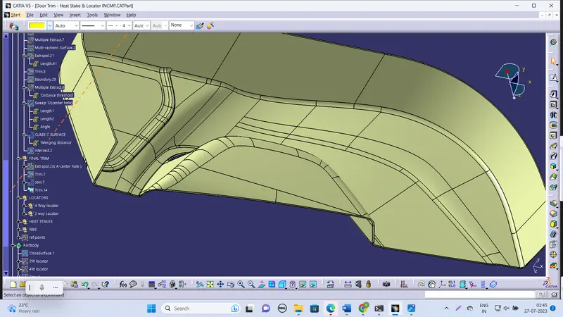
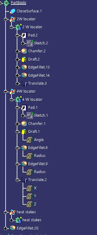
After creating a main body I've created the engineering features like 4 WAY locator and two WAY locator and heat stakes and ribs.
4 way locator
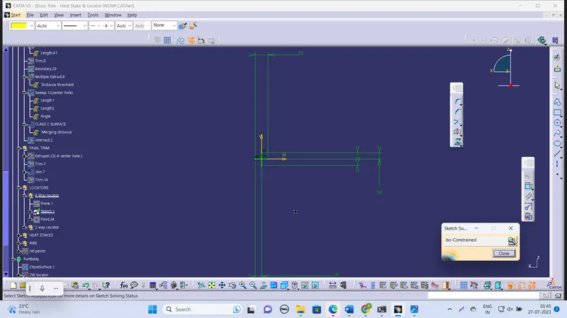
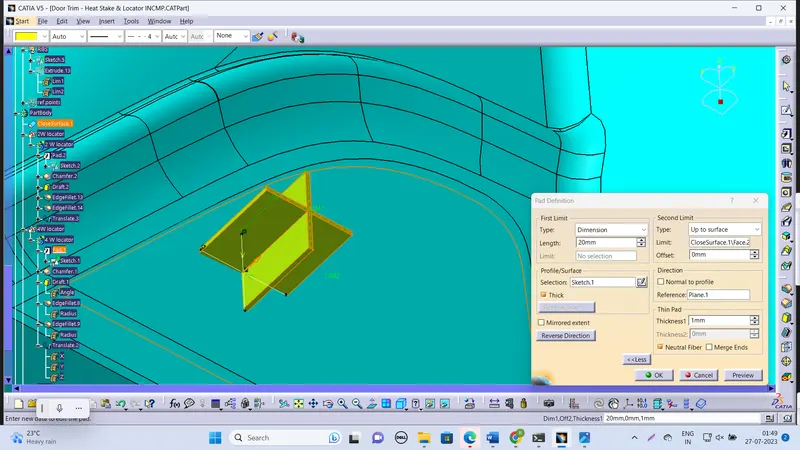
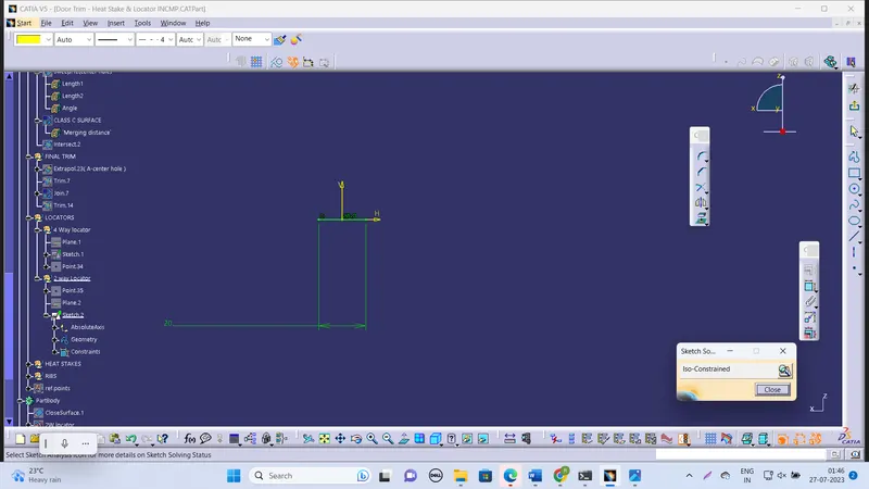
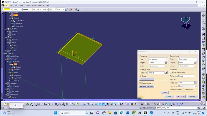
2 way locators sketch
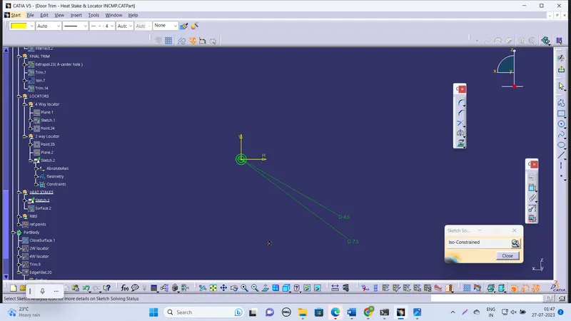
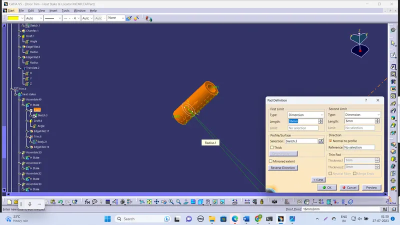
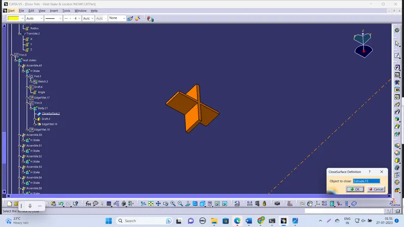
Heat steak sketch
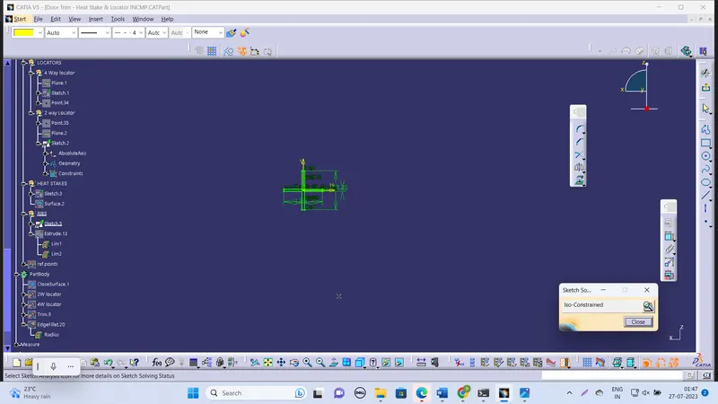
ribs sketch
Draft analysis in CATIA is a powerful tool used to evaluate the manufacturability of a designed part for molding processes. By analyzing the draft angles of the part's surfaces, it helps to determine whether the component can be easily ejected from the mold without any interference or undercuts. The draft analysis provides visual feedback using color mapping to identify regions that do not meet the required draft angle criteria.
This analysis is crucial during the early stages of product development, as it allows designers and engineers to identify potential issues that could arise during the molding process. By ensuring sufficient draft angles, the risk of production problems and costly modifications to the mold can be minimized.
During the draft analysis, CATIA examines the angles between the part's surfaces and the direction of mold opening. Proper draft angles enable smooth ejection from the mold without causing any damage to the part or the mold itself. The color range displayed on the analyzed element helps users quickly visualize problematic areas that require adjustments to meet the necessary draft angle specifications.
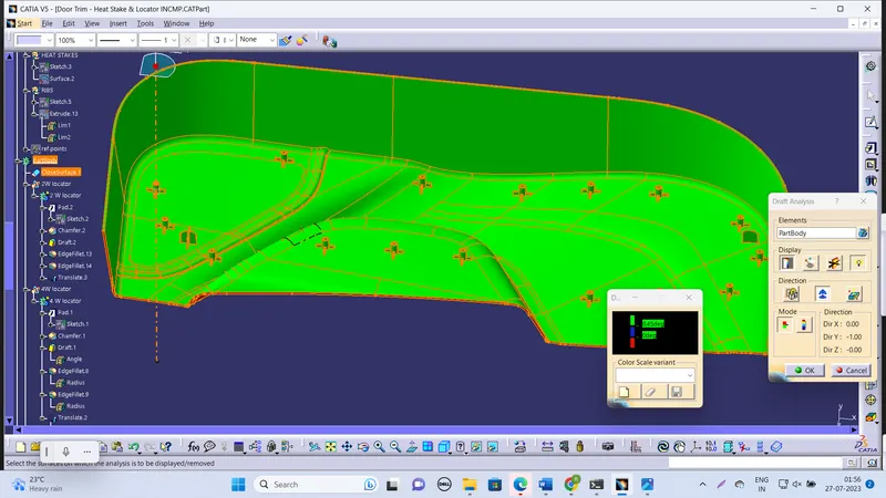
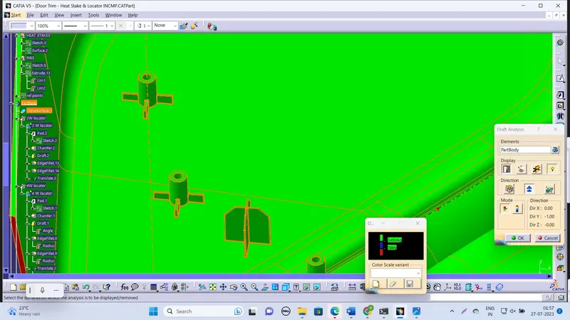
1.Here the draft degree of three degrees are used for the main component and 0.5 degree is used for the engineering features like it takes ribs and locators
2. Draft analysis of Class A is okey
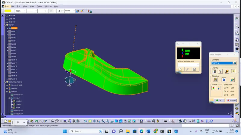
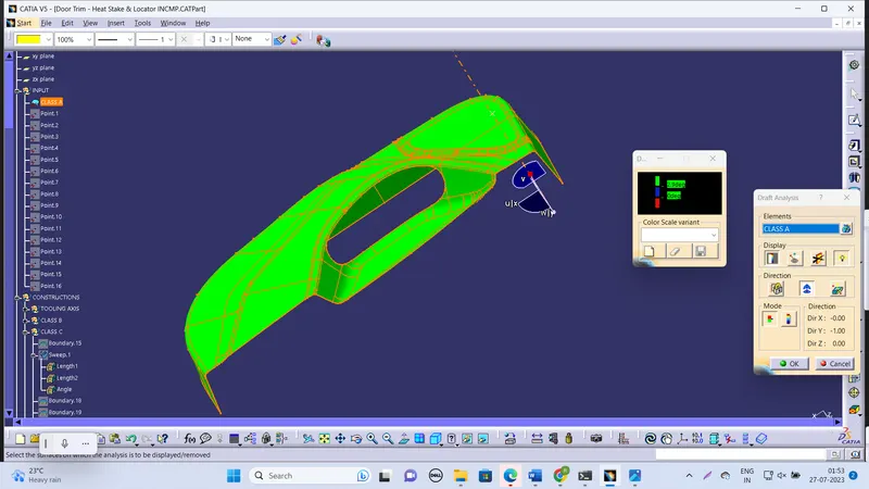
3. Draft analyst of the solid
4. here at the left and right extremes as shown in figure it is not clear so it is it should be noticed by the stylish engineer
That is clear at 2.6 degrees as shown in the below figures
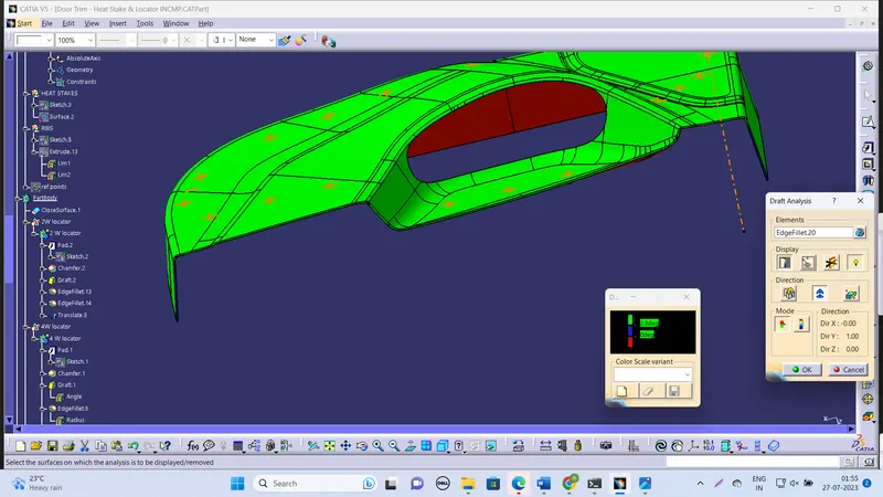
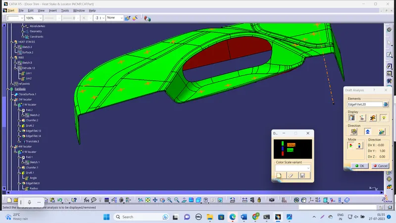
5. The draft analysis is clearing for 0.5 degrees for all the engineering features like heat stakes and locators
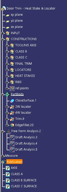
Tree structure
different views
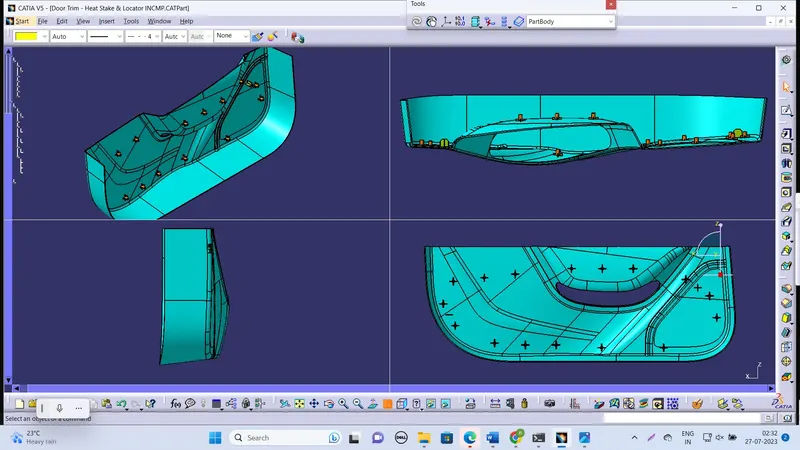
finally the work is done and there is a small draft is not clear that should be corrected as mentioned earlier.