Week 10 - Challenge 3 - Door Trim Lower with Engineering Features
AIM -
Create the Door Trim Lower Plastic component through the given Class-A surface. To begin with, the tooling axis for the given Class-A Surface should be created meeting the requirements of the draft angle and at the end perform the Draft analysis on the model.
Create the Heat Stakes and the locators considering the design rules mentioned in the video for the door applique.
THEORY -
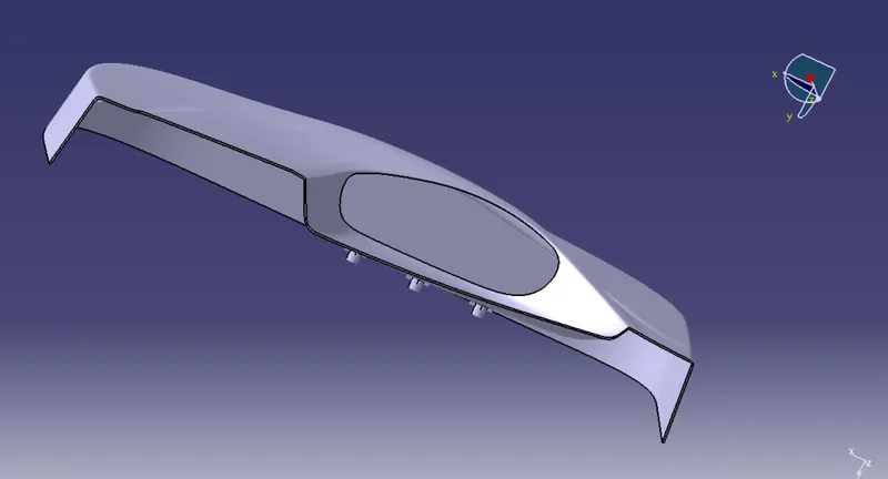
CLASS A SURFACE - We have a given Class A surface in this challenge.
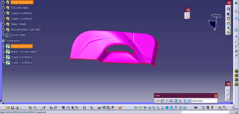
TOOLING AXIS - To create a tooling axis we check the whole given class A and then pick the flat surface on it after picking that surface we have to make the point on it by giving 0 in coordinates and making a straight line with reference to the axis and the following picture shows the tooling axis.
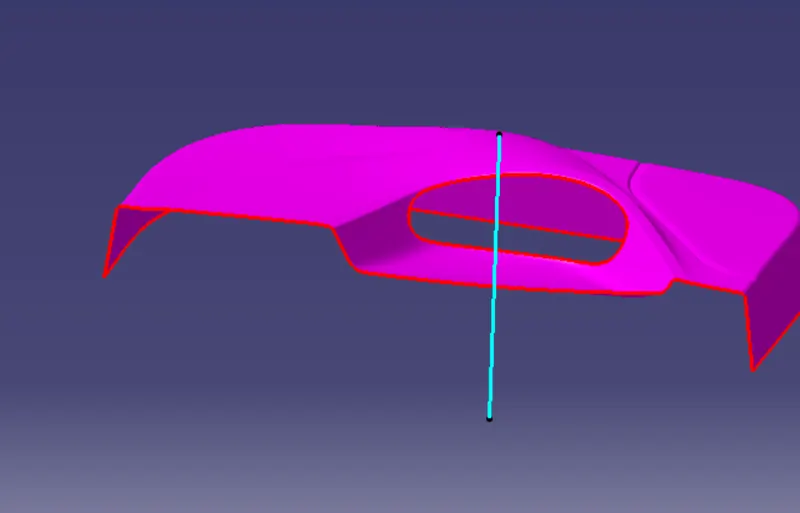
The blue line indicates the tooling axis.
CLASS B SURFACE - For the class B surface we have to make an offset of Class A at 2.5 mm.
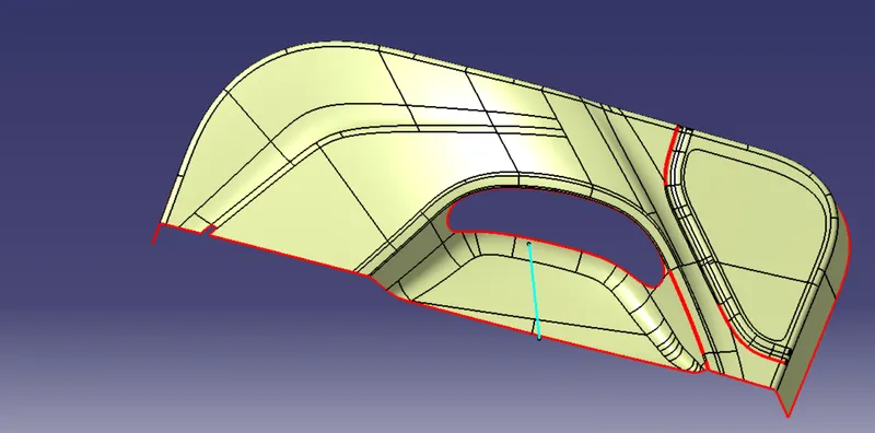
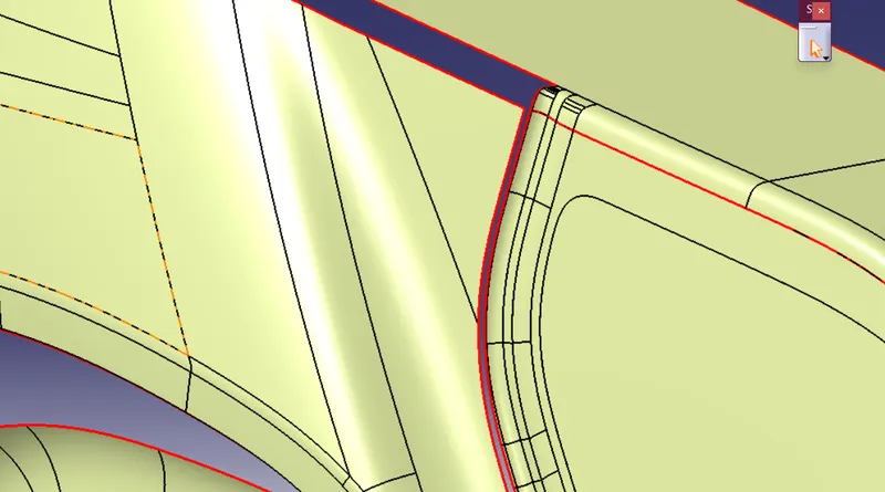
After taking off set we have a surface with 4 patches in it now we have to fill these patches so we work on each patch one by one and we are following the extrapolating and trimming approach to properly fill the patches.
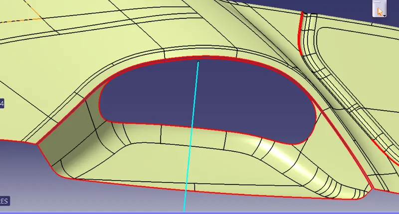
After extrapolating and trimming the surface will look like this .
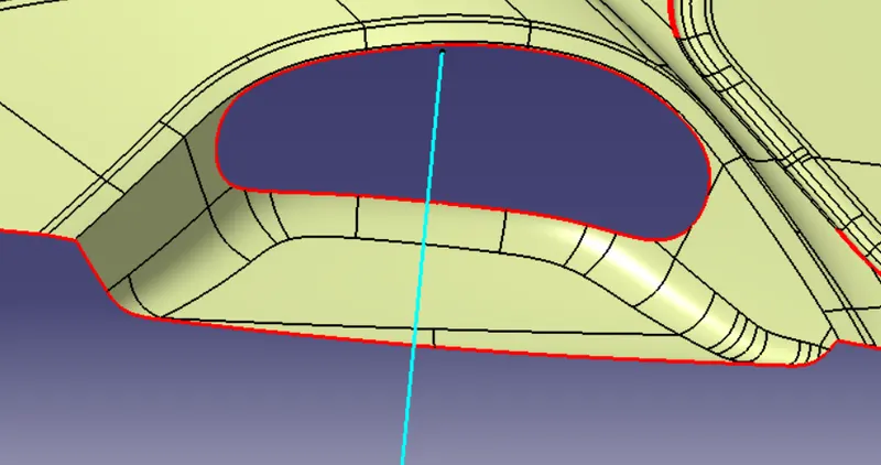
Now by following the same approach, we can fill all the other patches.
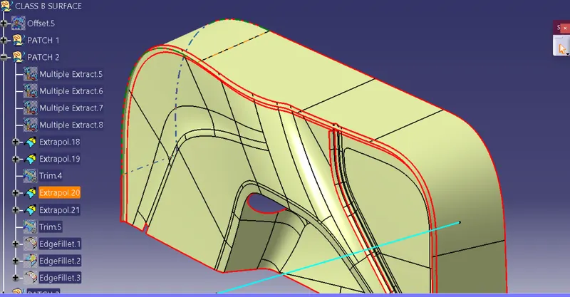
A complete patchless B surface would look like this.
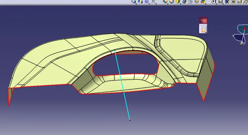
CLASS C SURFACE - Class C surface is a link between Class A and Class b the class A and B will look like this after
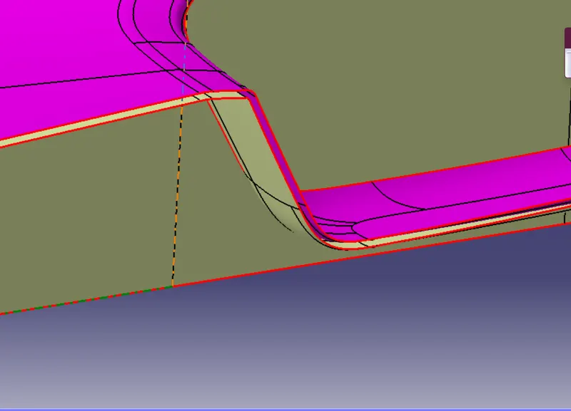
So to fill the gap and to make a whole closed surface we have to make a surface between them and to make the surface we have to use the sweep command. For using the sweep command we have to take boundaries first from class A surface and then choose (With Reference surface) in subtype with a 90-degree angle and 10 mm length.
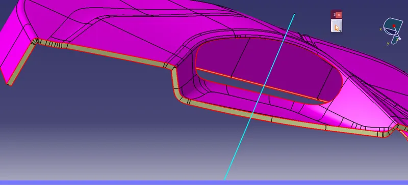
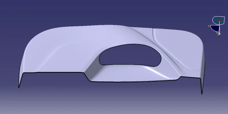
COMPLETED SURFACE - After completing All Class surfaces we have to Join Class C and Class A and then trim it with class b so that we got a closed surface in all three dimensions.
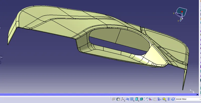
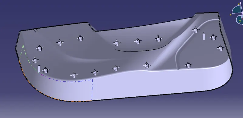
From this point, Our work in the surface workbench is almost completed and now we move to the part workbench. After moving in part workbench we have to run close surface to make it a solid part so in command we have to select our closed surface then it will create a solid part.
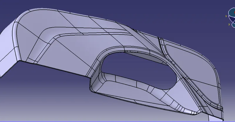
POINTS IN GIVEN CAT PART FILE - We have some given points on the body to create some Four-way locators and Heat stakes.
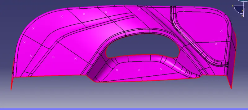
FOUR-WAY LOCATORS - Four-way locators are the locators made to place the part correctly because as per its name, it's used to identify the part fitting location. For making a four-way locator we have to follow these steps.
- we have to make as ketch on specified point on this surface i.e
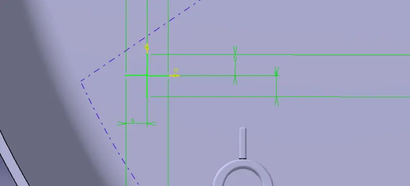
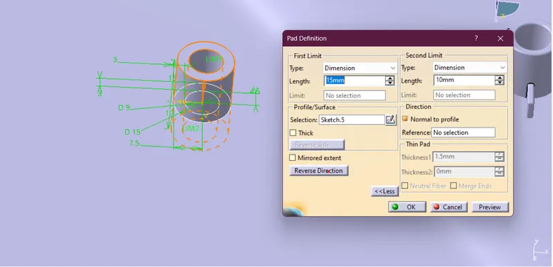
- After that, we have to pad it with these given details.
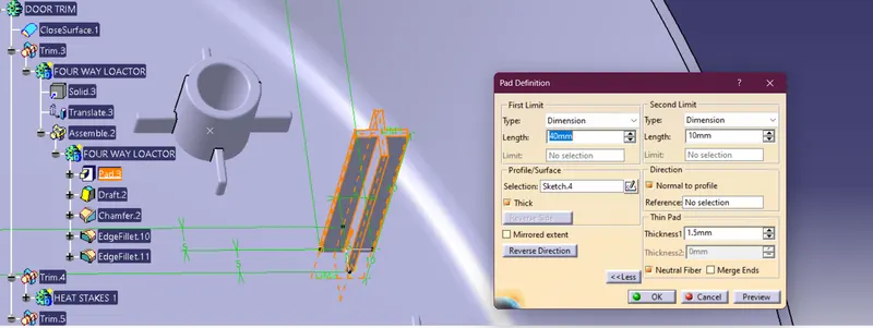
-After Applying the pad command we have to make it suitable according to the door trim so we have to draft it
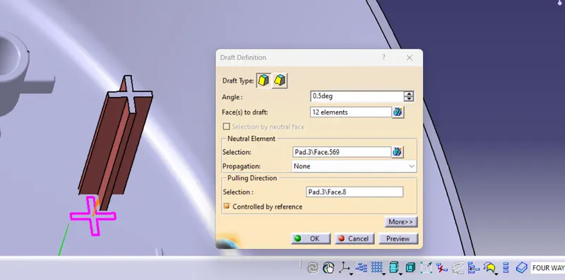
-After applying the draft we use chamfer.
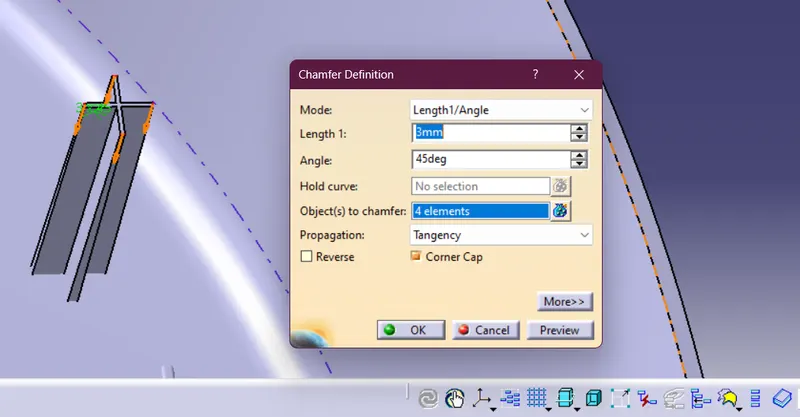
- After chamfer, we have to give edge fillets and our four-way locators are ready.
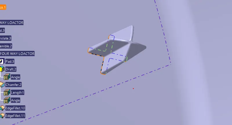
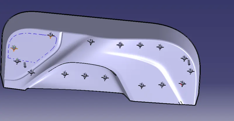
- Now we just have to copy and paste it to another point just by using the translate command with point-to-point translation.
HEAT STAKES - Heat stakes are another engineering feature that is used to make fitment of screws for making it we have to follow these steps.
- First, we have to draw a sketch with the following dimensions.
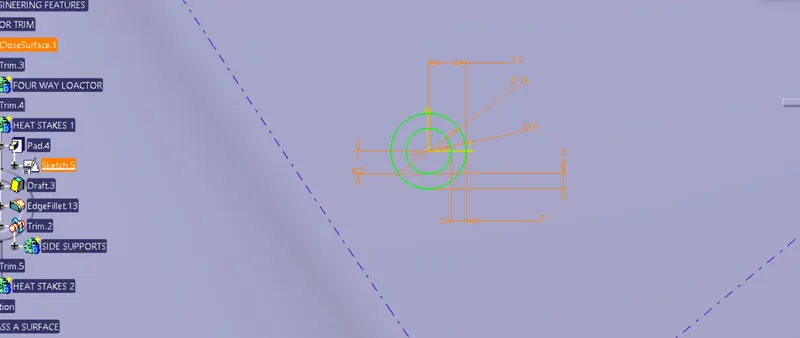
- Now we have to use the Pad tool to make it 3d and solid.
- By using draft we get
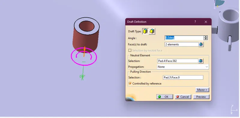
- Now we have to make side supports of this for this we have to make a sketch and give them a pad at the neutral face and trim it with the previous pad and as a result we get a completed heat stake.
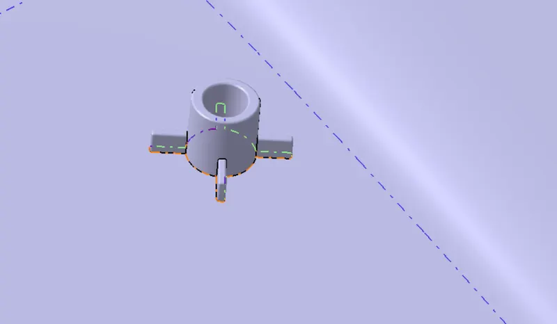
Now we just have to translate the heat stakes at given points and after translation, we get this -
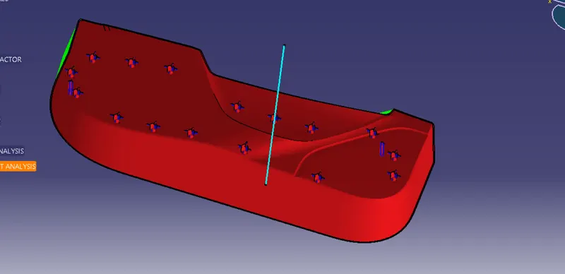
DRAFT ANALYSIS -
Class A draft analysis -
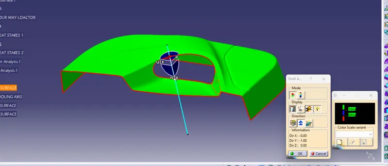
final part draft analysis -
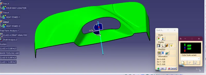
FULL BODY -
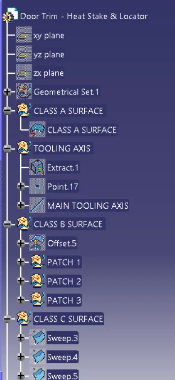
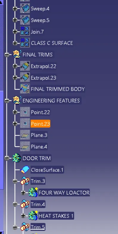
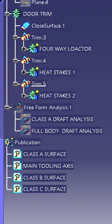
TREE STRUCTURE -