Week 10 - Challenge 3 - Door Trim Lower with Engineering Features
DESIGN OF THE DOOR TRIM LOWER WITH ENGINEERING FEATURES INCLUS HEAT STAKES,LOCATORS & RIBS
Aim: To design the door trim lower component from the given class A surface and create the engineering features ( heat stakes and locators ) on the component using CATIA V5 software
Objectives:
Creation of Tooling axis with appropriate draft angle.Creation of other surfaces (eg, B and C surfaces) for creating a solid component. • Perform Draft analysis on Class A surface and Solid model hence created.
Procedure followed:
The following steps are included while designing the door handle with B side features
- Tooling axis creation
- Draft analysis of class A surface
- Class B surface generation
- class C surface generation
- Final trim
- Solid body generation
- Draft analysis of the solid body
- Locator creation
- Heat stake creation
- Translation
- Draft analysis of the B side features
Class A surface:
Class a surface is an asthetic surface with a polished surface which will be visible for the customers, and with the aid of the class A we could be able top geneate the class B and class C surfaces
Class B surface:
class B is an engineering surface where the B side features include the ribs, screw bosses , doghouses are located
Class C surface:
Class c is an intermediate surface between the class A and class B surfaces.It is generated by sweep feature either with reference surface or with the draft direction.If the generated C surface is parallel yo the tooling axis then we make the aid of the draft direction or else proceed with the reference surface
Commands deployed:
Surface commands:
- Extract
- Boundary
- Extrapolate
- Sweep
- Join
- Trim
- Intersect
- Multi section surface
- Surface extrude
- Multi extract
Part Workbench commands:
- solid surface
- Thicken
- Pad
- Draft
- Fillet
Tooling axis creation:

Draft analysis on class A surface:
Now perform the draft analysis of the Class A surface with respect to the tooling axis created so that the surface of the Class A need to clear the draft of 3mm. So the class A surface is perfectly claering the draft analysis so we need to move further for the creation of the class B surface
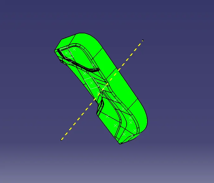
Class B surface creation:
Now offset the class a surface to a thickness value of 2.5mm so there in the offsetted surface we encounter some patches, so we need to work on them to create the Class b surface
For working on these patrches I divided the class A surface into 4individual patches excluding the fillets as the fillets would create miore problem so we need to apply them at the end and extrapolate them to a sufficient length
so , thet proper interaction should be formed between the patches.Now apply the trim to form a combined surface and apply the fillet value to obtain the required class B surface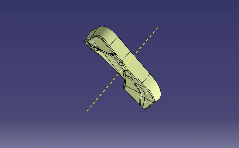
CREATION OF LOCATORS:
To create the locators, I created a sketch on the body. After creating the sketch, I pad it 22mm in height and thicken it to 1.3mm and I drafted it with 0.5deg in the direction of the tooling axis. I gave 5mm of chamfer with 45deg of inclination and after I gave a fillet of 0.3mm radius. 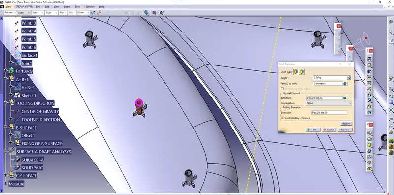
please find attached cat.prt