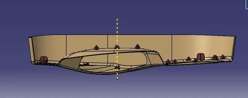
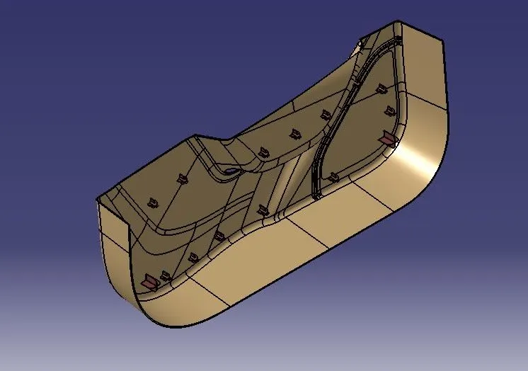
Week 10 - Challenge 3 - Door Trim Lower with Engineering Features
Door Trim Lower with Engineering Features
OBJECTIVE:-
• Creation of the Tooling axis with appropriate draft angle.
• Creation of other surfaces (eg, B and C surfaces) for creating a solid component.
• Perform Draft analysis on Class A surface and Solid model.
REPORT
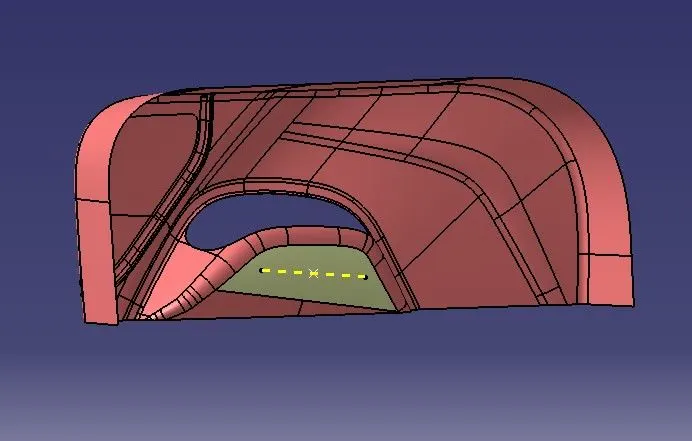
TOOLING AXIS
Tooling axis is the direction in which mold or core and cavity opens. The ejection of the part from mold depends on the draft. A zero draft can result in difficult or no ejection due to shrinkage. It is recommended to add a minimum of 0.5 to 1 degree of the draft for non-textured surface & 3 to 5 degree of draft for textured surfaces.
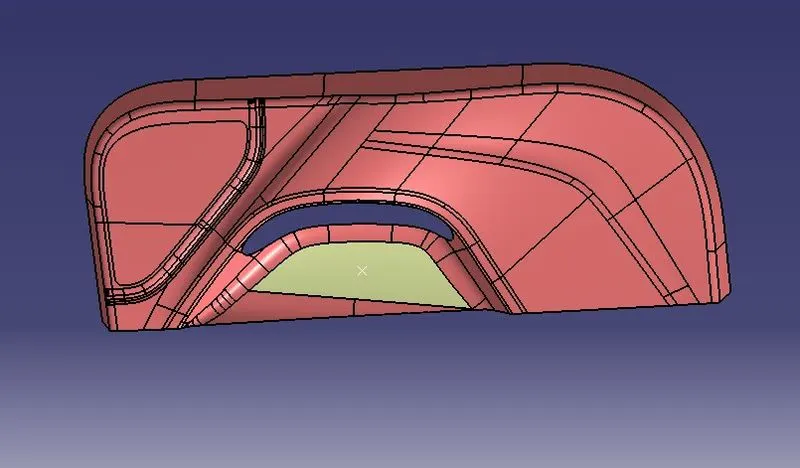
Steps used to create tooling axis for the given Class-A Surface
1.Extract the surface from Class A surface by using extract command and create a point in it.
2. Define the tooling axis in y direction.
SURFACES
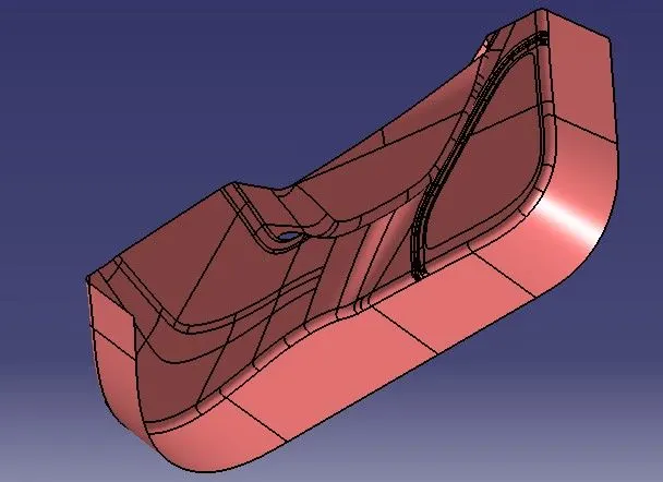
CLASS A SURFACE
It gives the aesthetic of the component which is created by the styling team and gives to the part design engineer to create the part with all engineering aspects.
CLASS B SURFACE
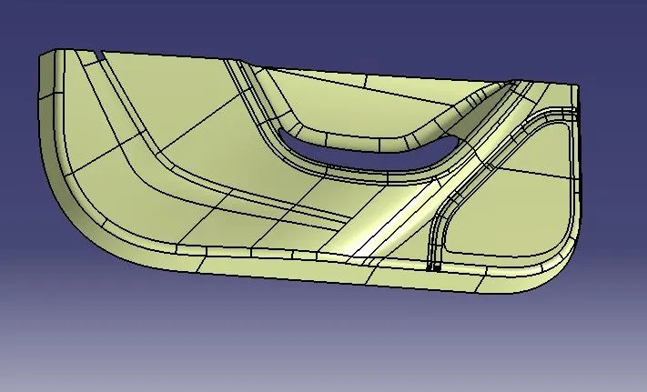
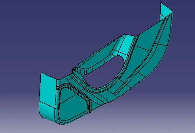
Class B surface is created by Offseting the class-A surface to 3mm inward direction. The patches are created while offsetting the surface. Rework on the patches using the features like extract, multi-extract, sweep, multi-section surfaces, extrapolate.
Class B surface is created.
CLASS C SURFACE
The surface that joins class-A and class-B surfaces are class-C surfaces. Class C is often specified for interior surfaces not readily visible, surfaces that will be covered by another part when assembledThe Class C finish allows more imperfections than Class A or B. Class C is often specified for interior surfaces not readily visible, surfaces that will be covered by another part when assembled, or surfaces which the Customer feels do not need to meet a high cosmetic finish.
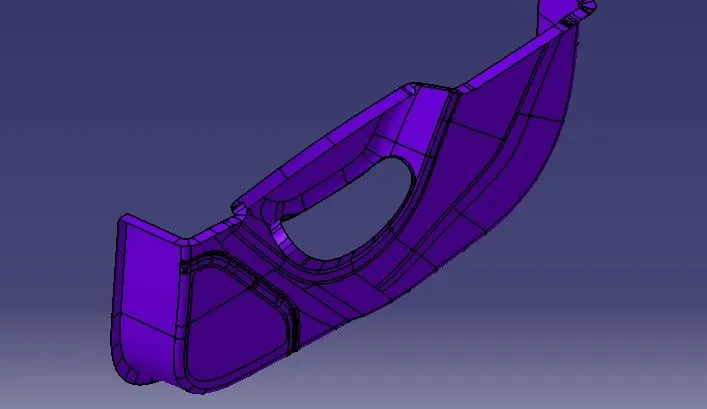
CLASS B is trimmed with CLASS A AND C.
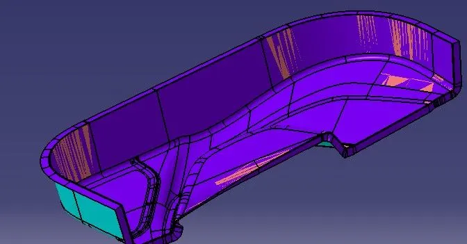
Closed A, B, C SURFAC
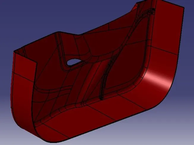
HEAT STAKES AND LOCATORS
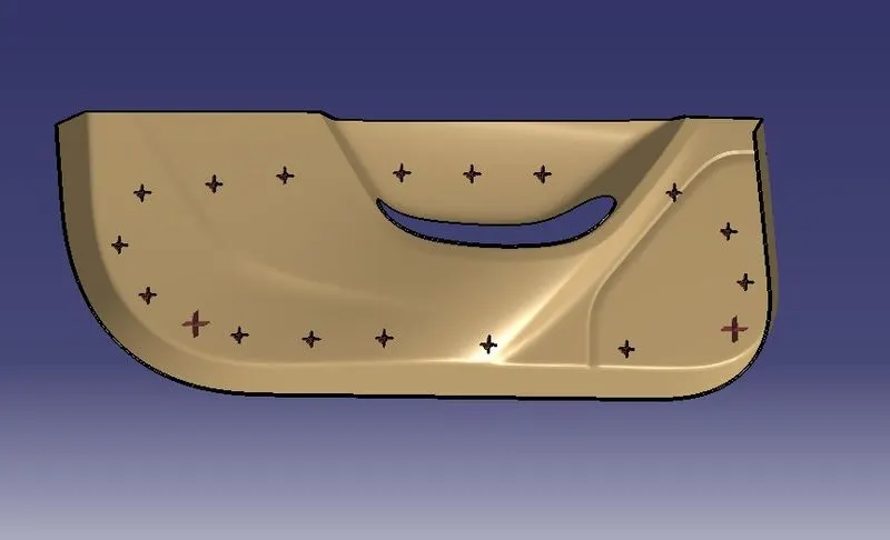
The locators restrict all the other degrees of freedom except the translation along the direction of tooling axis along y-axis. For restricting that degree of freedom we will be using the heat stakes.
In heat staking, we use local heating and cooling to raise the temperature of plastic components and allow plastic reforming to be carried out.
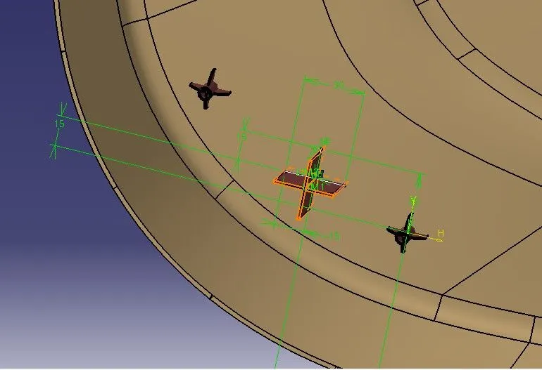
The draft is applied to the sides of the locators. As per the design rule, the ideal draft angle is 0.5 deg
The fillet is applied to the faces of the locators. As per the design rule, the fillet can be 0.3 mm.
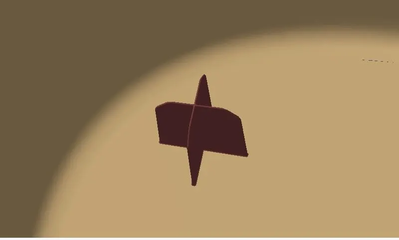
The heat stakes will enter the mating component and using a heat staking machine these heat stakes are melted and cooled. When cooled this will get hardened and the two components will stick together. Thus all degrees of freedom are arrested
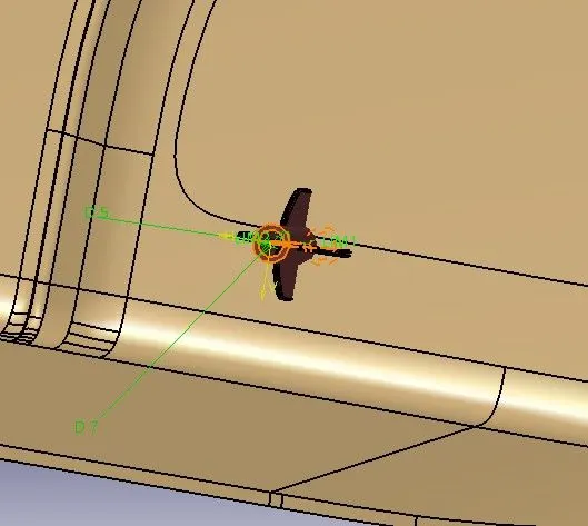
Now we will see how the plastic part is fixed onto the other plastic part. The door applique is fixed on to the door surface with the help of locators and heat stakes. Every component in space has 12 degrees of freedom. So these locators and heat stakes restrict all these degrees of freedom.
Locators are 4-way locators. The locators will follow the rib design guidelines and will be given a minimum draft of 0.5 degrees and a minimum fillet of 0.3mm and an entry chamfer of 3mm. This entry chamfer is given so that the locators can mate with the other part easily.
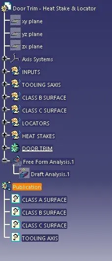
TREE STRUCTURE
DRAFT ANALYSIS
Draft analysis is performed based on color ranges identifying zones on the analyzed element where the deviation from the draft direction at any point, corresponds to specified values. Minimum draft angle is considered as 3 degree.
- Screenshots of the Draft analysis report for both the given Class-A surface and the final plastic component.
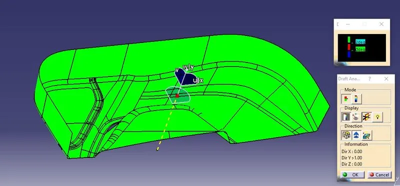
- DRAFT ANALYSIS OF FINAL COMPONENT
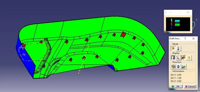
FINAL COMPONENT