Section Modulus calculation and optimization
Section Modulus calculation and optimization
OBJECTIVE:-
- Breif explanation of section modulus and its calculations.
- To come up with a new section that has an improved Section Modulus compared to the previous one and mention what changes had made which resulted in the increased strength.
REPORT:
WHAT IS SECTION MODULUS ?
It is termed as the ratio of second moment of area and distance from N.A (Neutral axis) to the extreme fiber. Also it is the measure of strength of given member. The stress in the outermost section of beam is computed with the help of section modulus. It is indicated by S.
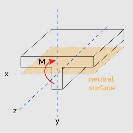
Section modulus is indicated as follows:
S=I/Ymax
Here, I is “moment of inertia” and y is distance from “neutral axis” to top or bottom of fiber.
Unit of a “section modulus” is in.3(mm3).
Section modulus depends only on the cross section shape of the beam. Cross section shapes like rectangular, square, circular, I section and T, composite section etc.
For symmetric sections, the value of “section modulus” is for both above and below of centroid of the fiber.
An asymmetric section has two values for top and bottom of the fiber due to different distance from centroid to the top and bottom of the material, the maximum “section modulus” is S m ax and the minimum section modulus is S min.
Importance:
It is significant for beam and flexural member design.
More the section modulus, more the member is resistant to bending of the beam.
It is easier to calculate stresses in beam and an exact measure of strength of steel.
If two beams are made of same material and comparing the “section modulus” of two beams, the beam with bigger section modulus will be tougher and more capable to withstand larger loads.
WHERE SECTION MODULUS CAME FROM ? & WHAT IS ELASTIC SECTION MODULUS ?
To know where the section modulus comes from, let's remember the widely known flexure formula used to determine the maximum stress in a beam subjected to bending:
σmax = Mc/I
where, c=Ymax
- σmax - maximum normal stress in the beam. This occurs at the distance c from the neutral axis.
- c - largest perpendicular distance from the neutral axis to a point in the section.
- M - bending moment about the neutral axis.
- I - area moment of inertia of the beam cross section about the neutral axis.
Just like the area moment of inertia, the distance c depends solely on the geometry of the section. We can combine I and c and generate a new geometrical property that entirely accounts for the effects of the geometry on the normal stress. This property is known as the section modulus or elastic section modulus:
S=I/c
With this new property, we can now calculate the maximum normal stress due to bending by only knowing M and S:
σmax=M/S
As well as for the moment of inertia, we can define the section modulus for the x and y directions. The axis to choose will depend on the direction of the momentum vector. For example, if the moment vector acts in the x-direction (the most common situation), we choose the section modulus in the x-direction.
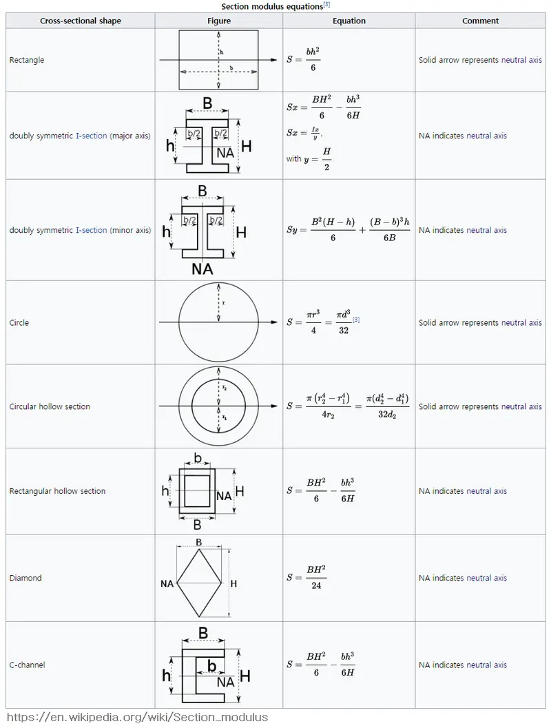
Formulas to calculate the section modulus:
In the following table, you can look at the elastic and plastic section modulus formulas, which are the ones this section modulus calculator uses. Scroll sideways to display the whole table.
WHAT IS PLASTIC SECTION MODULUS ?
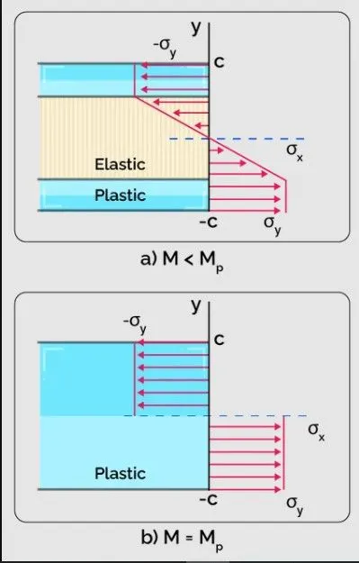
The plastic section modulus has a similar function to its elastic counterpart, but for situations in which we surpass the yield strength of the material and it no more exhibits a linear elastic behavior. The elastic section modulus makes it possible to calculate the plastic moment of the section:
Mp=ZσY
- Mp - Plastic moment;
- Z - Plastic section modulus; and
- σY - Yield strength of the beam material.
The plastic moment refers to the moment required to cause a plastic deformation across all the fibers of the beam section. As we know, for bending, the normal stress is higher at the points farthest from the neutral axis, and, therefore, it will reach the yield strength first at those points. Once the moment (M) equals the plastic moment (Mp), the yield strength will have reached the whole section.
DESIGN STUDY:
The Intersection of the design was taken and then section Inertia Analysis was done:-
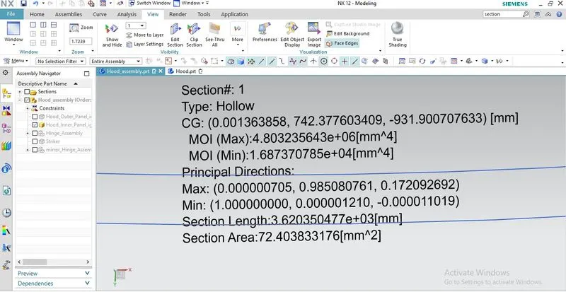
Moment of inertia(max) = 4.803235643×10^6×mm^4
Moment of inertia(min) = 1.68730785×10^4×mm^4
Y=485.7599/2=242.8799 mm
S=I/Y
S=1.68730785×10^4 /242.87=69.44mm^3
DESIGN OPTIMIZATION:
By increasing the depth of the inner panel by 0.45 mm
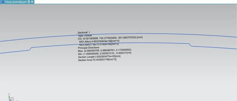
Moment of inertia(max) = 4.501403273×10^6×mm^4
Moment of inertia(min) = 1.71358471×10^4×mm^4
Y=485.7599/2=242.8799 mm
S=I/Y
S= 1.71358471×10^4/242.87= 70.55mm^3
CONCLUSION:
We have come to conclusion that the change in moment of inertia by changing the design paramerter (depth) results in change of section modulus. The more the section modulus, more the member is resistant to the bending which results in the increase of strength of material.