Fender Design - Wheel Arch Challenge
Fender Design - Wheel Arch
OBJECTIVE:-
- Brief note on fender.
- Wheel arch gap and different standards.
- Calculation of wheel arch gap at required points and checking whether the car passes the European standard.
REPORT:-
WHAT IS FENDER ?
Fender is the side closing component for the engine compartment. It’s major role is to avoid chipping sand, small stones and mud particles inside the engine compartment when the wheels rotate. Fender also plays a major role to prevent injuries for the pedestrians. Basically we have two types of fender half bumper type and the full bumper type. The differences between two types are its size. The raw material usage plays a major role and so half bumper is economical. Drip area and wheel arch are one of the two important things to be considered while designing fender.
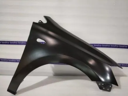
WHAT IS WHEEL ARCH GAP AND WHAT ARE DIFFERENT STANDARDS ?
The wheel arch is the semicircular part positioned above the wheel of a vehicle. The most important body change was that the front wheel arch was cut higher into the fender.
There are standards all over the world for wheel arch of a car. Country to country they will fix a certain regulation considering the infrastructure available in their country. Basically when the wheel is seen from the front side and if it was outside the car the chipping will be more and that causes damage to the engine compartment and the pedestrians.
Japan standard:
It says we need to draw two lines with wheel center point and reference to vertical line on the wheel with 30o on the left and 50o on the right. Projecting the points to the wheel arch the points must be 5mm or above.
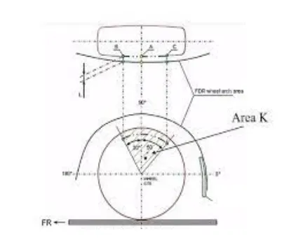
European standard:
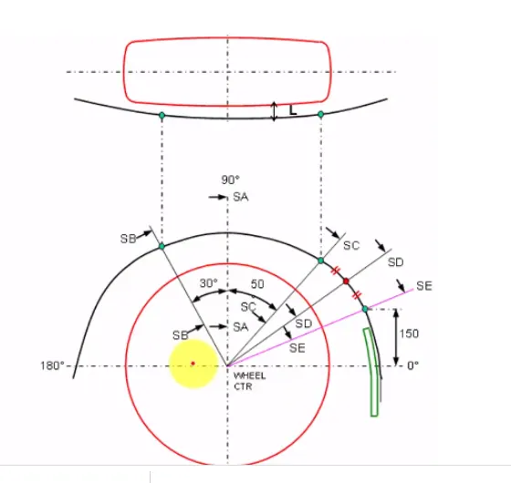
As like Japan it also says to draw two lines with wheel center point and reference to vertical line on the wheel with 30o on the left and 50o on the right. Projecting the points to the wheel arch the points must be 10mm or above. And additionally we will have to take a 150mm point from the zero or horizontal line of the wheel and also in between the 150mm point and the 50o point we will also take a midpoint. Along with this we need to measure “a” the distance between the outer most layers and the SB, SC should be above 5mm.
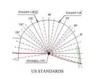
USA standards
In USA we need to take points for every 10o from -20o of the right side to 0 of the wheel and all must be 5mm or above.
WHEEL ARCH GAP CALCULATION ACCORDING TO EUROPEAN STANDARD
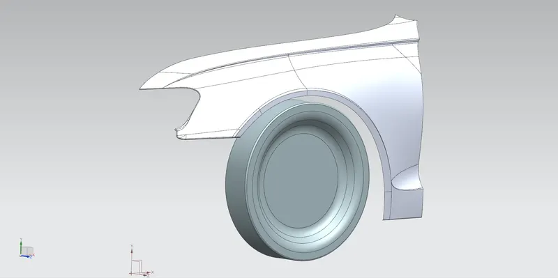
The following are the steps required for creating the sketch required for european standards:-
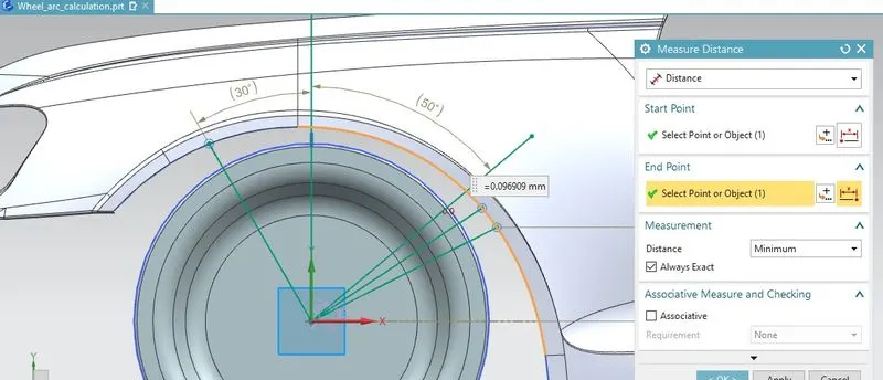
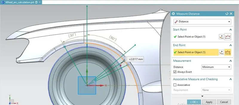
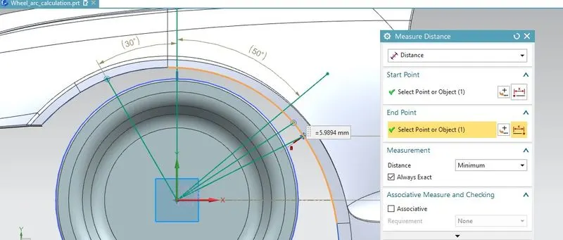
- To calculate the clearance between the wheel arch and the wheel, create a sketch on the outermost face of the wheel. Make a central horizontal axis line, a central vertical axis line 'SA', a line SB at 30° left to the central vertical axis, and a line SC at 50° right to the central vertical axis 'SC'. At a distance of 150 mm from the central horizontal axis line, draw a line 'SE', and a line 'SD' at mid point bisecting the 'SC' and 'SE'.
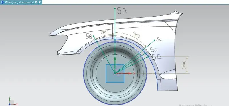
- Now, using the measure distance option in the analysis tab, the distance was measured from the points intersecting the arch by the lines SB, SA, SC, SD, SE to check and validate as per the European standard.
- Clearance 'L' at SB = 10mm
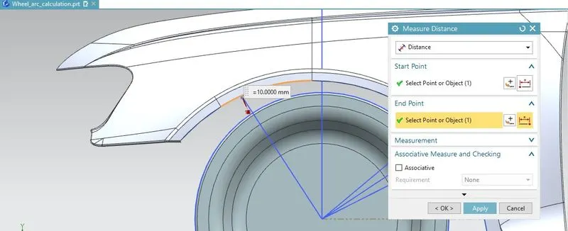
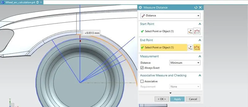
- Clearance 'L' at SA = 9.9513mm
- Clearance 'L' at SC =-0.096909mm
- Clearance 'L' at SD = -2.8117
- Clearance 'L' at SE = -5.9894
OBSERVATION:-
| POINTS | MEASURE | REMARKS |
| SA | 9.9513mm | FAIL |
| SB | 10mm | PASS |
| SC | -0.096909 | FAIL |
| SD | -2.8117 | FAIL |
| SE | -5.9894 | FAIL |
RESULT:-
From the above observation, we can conclude that only SB passed while SA, SC, SD, SE, fails the criteria. Therefore the design fails to comply with the European standard.