Week 10 - Challenge 3 - Door Trim Lower with Engineering Features
AIM- To create the Door Trim Lower Plastic component through the given Class-A surface considering the design rules .
Procedure
- Creating a tooling axis from the given class A surface and analysing the given class a surface.
- Creating class B and c surfaces from the class A surface & tooling axis with a draft angle of 3 degrees using sweep.
- Joining the class A and C surfaces and timmed with the B surface to form the closed surface .
- From the closed surface by using thickness we can get a solid body in part workbench.
- Creating the four way locator for the Door Trim considering the design rules
- Creating the heat stake for the Door Trim considering the design rules
Creating a tooling axis from the given class A surface using bisection method and analysingthe given class a surface.
- After visual inspection of the class A surface we can conclude that Y axis would be the best possible way to create the tooling axis.
- creating a intersecting line from the class A surface so that we can find the surfaces parallel to dummy tool which may create problem.
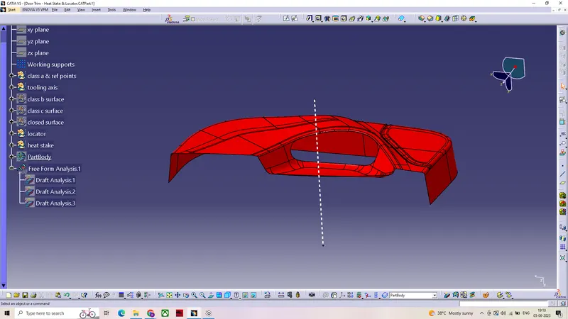
After performing drafting analysis on the class A surface using main tooling axis we can conclude that ,the chosen tooling axis is correct.
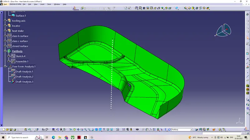
Creating class B and class C surfaces .
- Extracting the surfaces from the class A surface using extract then offsetted to form a thickness of 2.5mm .
- The obtained class B surface further modified and added fillet.
- To create a class C surface , boundary of the class A surface extracted using boundary command.
- By using boundary of the class A surface and the tooling axis as refrence class C surface extracted using sweep command
To create a closed thick surface the obtained calss c and a surfaces been trimmed using class B surface.
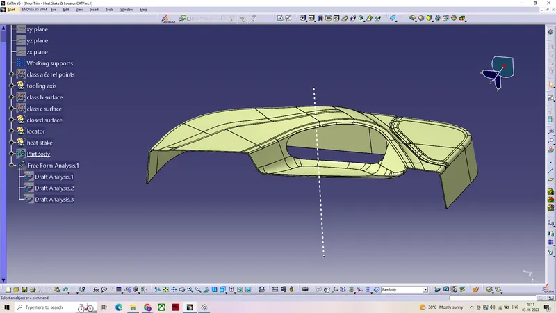
The obtained closed body then thickened in the part work bench to form a solid.
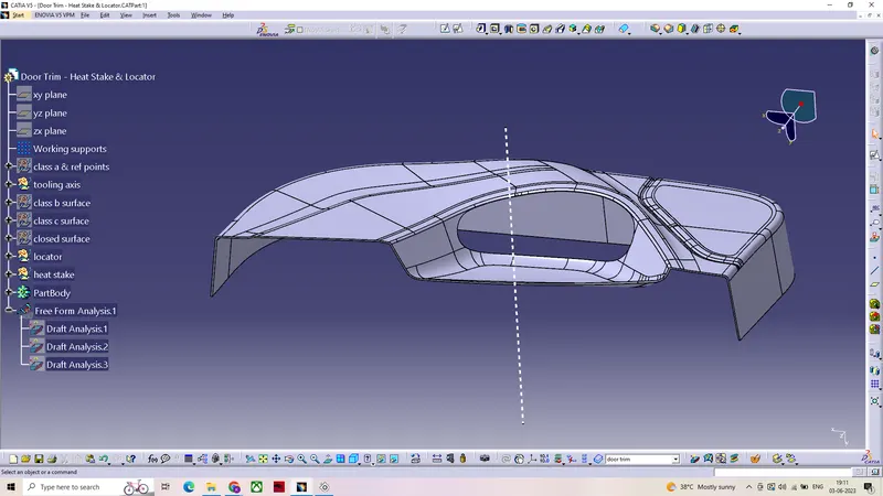
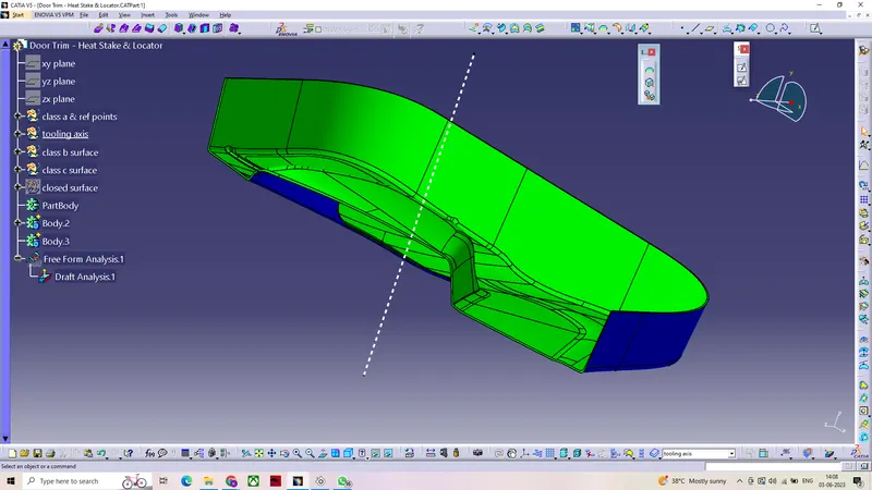
Draft analysis on the solid surface.
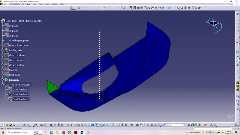
- First by setting the view parameters to material we can further proceed to draft analysis , after positioning the compass on the tooling axis we can get the draft anlysis.(min draft required for the component is set to 2.5 degrees)
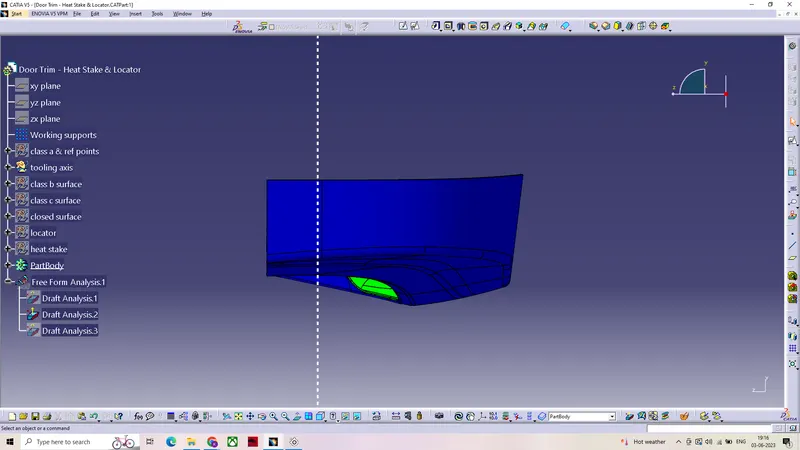
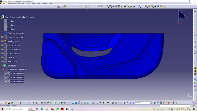
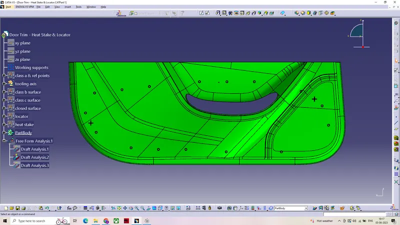
- Green region in the draft analysis indicates that the component has a minimum draft of 2.5 degrees.
- Blue region indicates no draft or negative draft.
- which maens the component cannot be manfacturable or it will create problems while manfacturing.
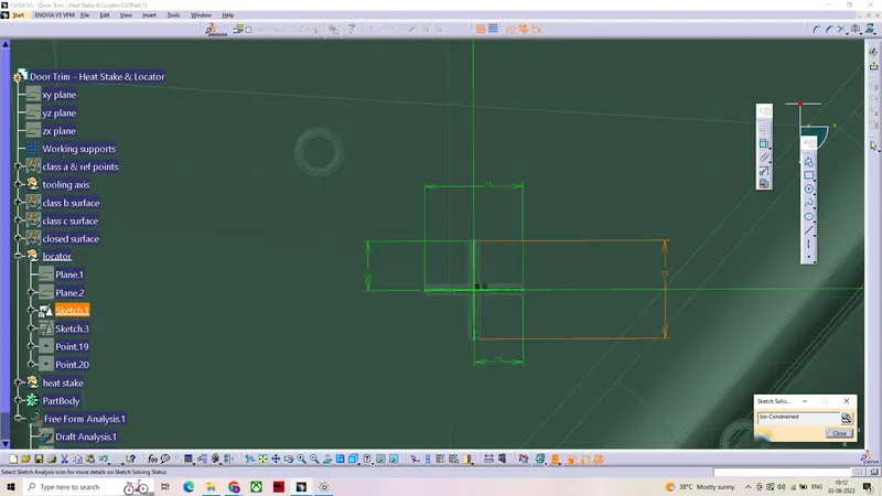
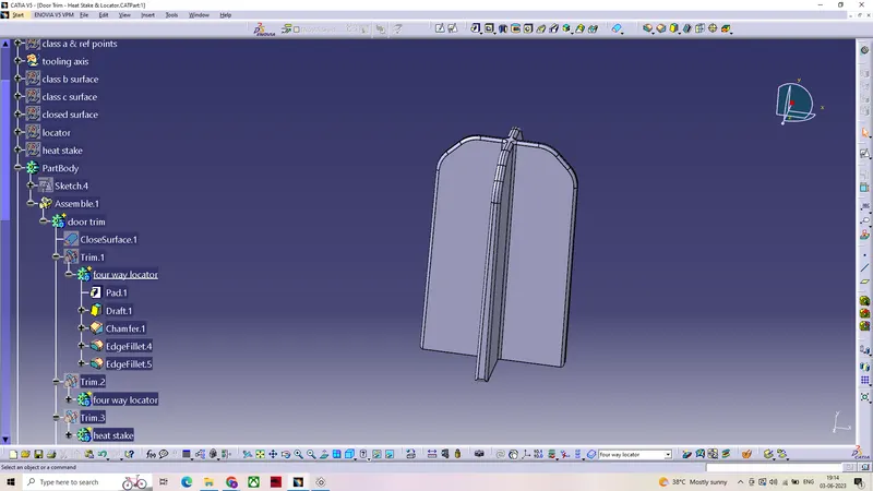
Sketch to pad four way locator with the specified rules.
After extruding the part body from the sketch using thickness (1.3mm) in pad ,then a draft of 0.5 degrees applied on each and every vertical faces .
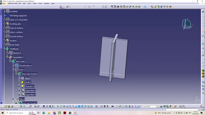
It was further modified by using chamfer and fillets.
Sketch to pad heat stakes with the specified rules.
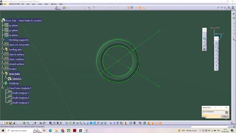
After extruding the part body from the sketch using pad ,then a draft of 0.5 degrees applied on each and every vertical faces .
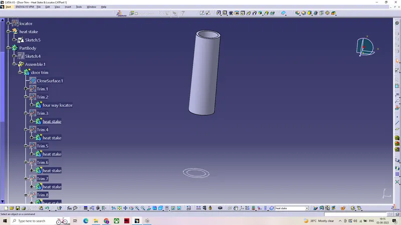
All the plastic components were attached to the door trim using boolean operations.

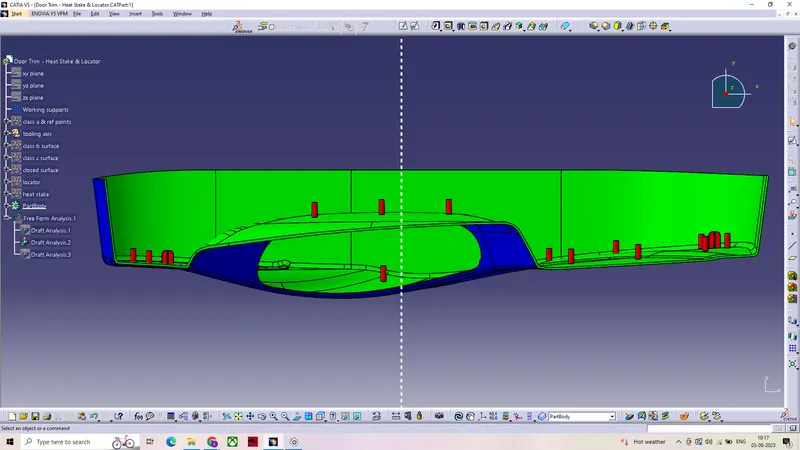
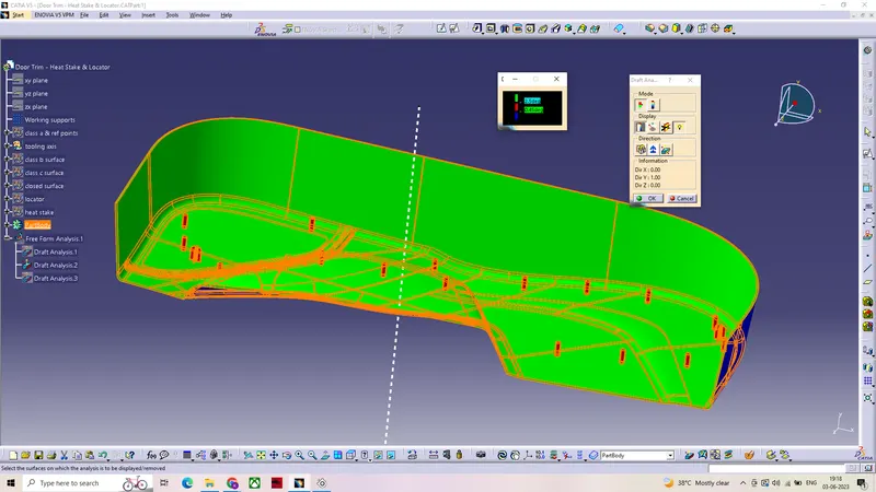
Draft analysis of the door trim with plastic components.
- Green region in the draft analysis indicates that the component has a minimum draft of 2.5 degrees.
- The region in red indicated a min draft of 0.45 degrees.
- Blue region indicates no draft or negative draft.
- which maens the component cannot be manfacturable or it will create problems while manfacturing.
ISOMETRIC VIEW
FRONT VIEW
LEFT VIEW
RIGHT VIEW
TOP VIEW