Week 10 - Challenge 3 - Door Trim Lower with Engineering Features
HEAT STAKES:
As the assembly engineering features like dog house , ribs and screw boss the heat stakes also created for the support in assemble the products.
Heat staking is the process of heating a plastic material to join thermoplastic material with thermoplastic component or any other dissimilar metal in manufacturing the components. Either one of the component must be a plastic componenent .It is the process of applying pulsed heat to the boss or stud and then reshape the material into a stake by using several tools. the plastic material in the boss is melted by thermal tip and fills and sticks to the component.
Thermoplastic materials such as polypropylene, polycarbonate etc., are used in heat staking process.
- It is quick and easy process of joining components
- Cost reduction, while using more screw and fasterenrs
- Joining of two dissimilar material parts
LOCATORS:
According to the 3-2-1 principle, supporting , positioning ,clamping are the main steps .We provide locators in assembly to restrict the degree of freedom of a component. Each and every component / part has 12 degree of freedom , that means the free movement of the component in free directions.
translation along +X,-X ,+Y,-Y ,+Z,-Z and rotation along X( clock wise, anti clock wise) , Y( clock wise ,anti cloc wise) , Z ( clock wise, anti clock wise) totaly 12 degree of freedom.
While assemle a component we need to restrict 11 degreed of freedom.
For the locators we can use 4-way locator( restrict degree of freedom in 4 dirctions) and 2-way locator(restrict degree of freedom in 2 dirctions).
To create a solid model by using close surface and create locators and heat stakes to it as per the given details.
DRAFT ANALYSIS:
The draft or taper angle is given to the component , because to ease the ejection of the mould part from the core and cavity without damage the walls or wear due to friction.
The draft analysis is performed to ensure the designed model is feasibile to manufacture according to the draft anlge. In draft analysis with different color variants we can identify the surfaces and even we can find the draft angle in a point by using running commamnd.
TOOLING AXIS:
To perform draft analysis we need tooling axis .It is the direction of which core and cavity moving direction.
Creation of Tooling axis:
To create tooling axis we have to select the appropriate direction , so from the view , in Y direction the surface is more visible.
Before creating tooling axis check with the given class A surface for proper continuity.Then intersect the surface along xy and yz planes. Bisect the Lines created from each intersection , we get a line and perform draft analysis with this line , if it satisfies the condition then make it as the tooling axis.
DRAFT ANALYSIS ON CLASS A SURFACE:
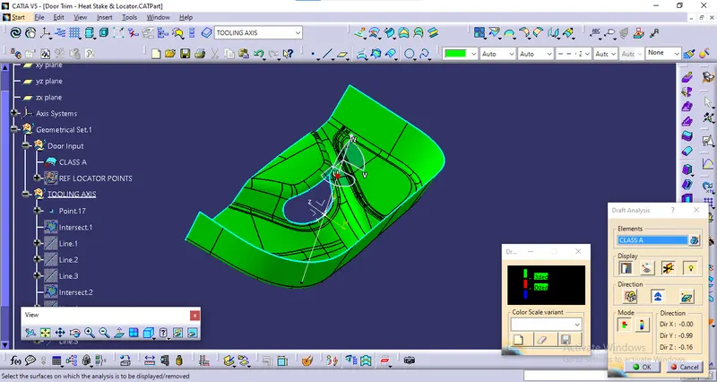
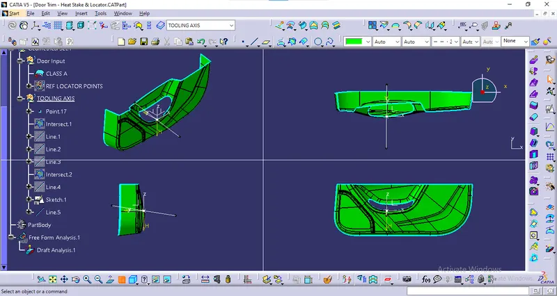
It clears the draft analysis. class A surface gives the aesthic look to thr component.
class A surface 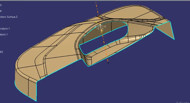
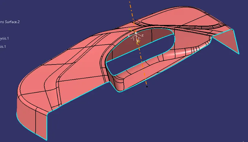
Class B surafce is created by offseting the the class A inwards in 2.5mm.In class B surface all the required assembly engineering features are created.
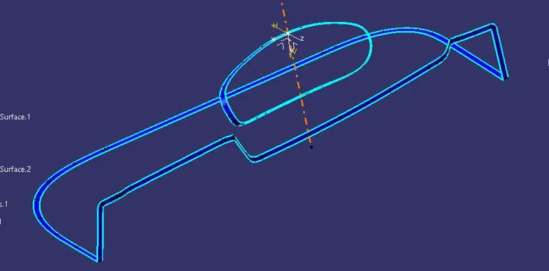
Class C surface is the joining surface of class A and class B.
SOLID MODEL OF CLOSE SURFACE:
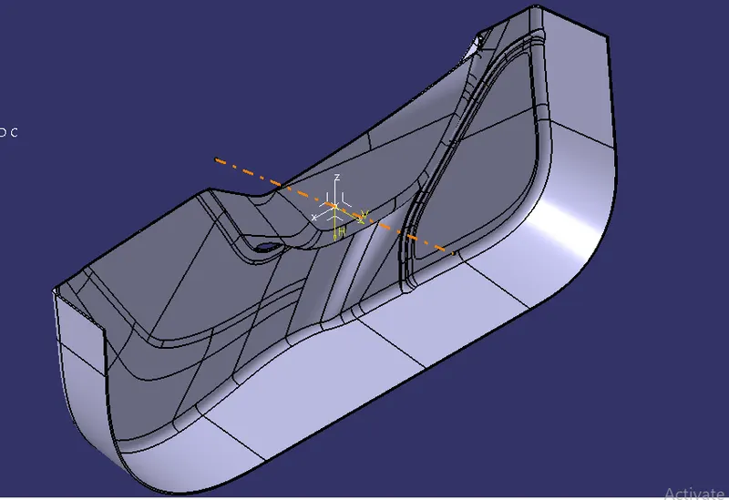
Solid model without Heat stakes anad Locators.
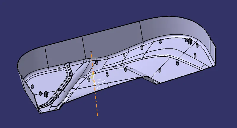
Solid model with Heat stakes and locators.
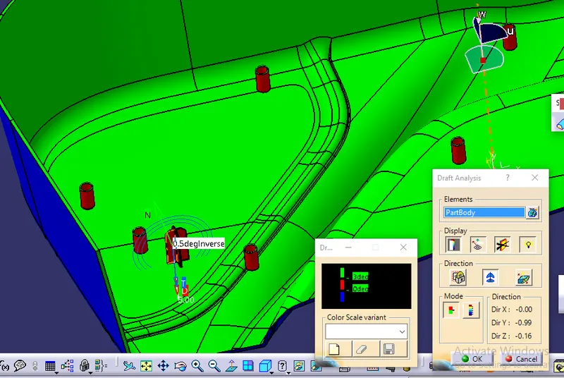
Draft analysis:
the draft analysis is performed with 3deg
color variant Green - above 3 deg
Red - between 0 - 3 deg
Blue - Less than 0 deg or inverse anlge
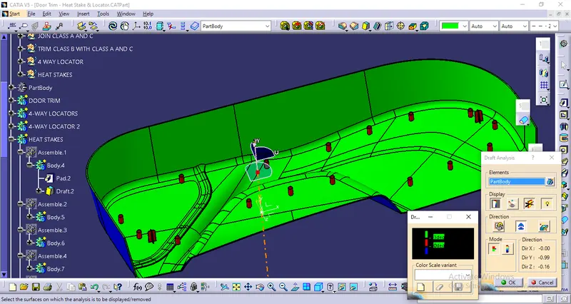
Here the result shows red color on walls of locator and heat stakes because , it is drafted with minimun draft of 0.5 deg. we can find it using running command.
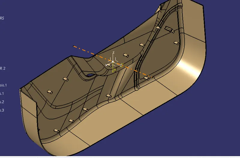
Oreintation Views :
Isometric view:
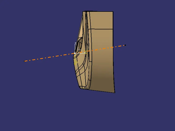
Front View:
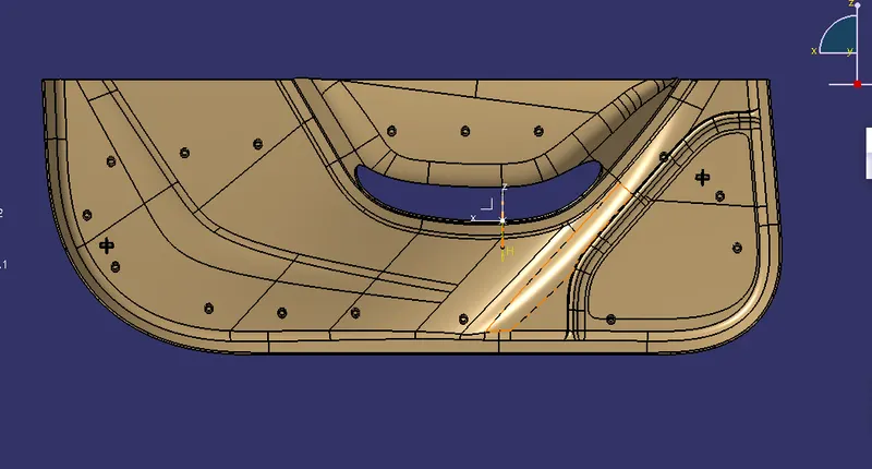
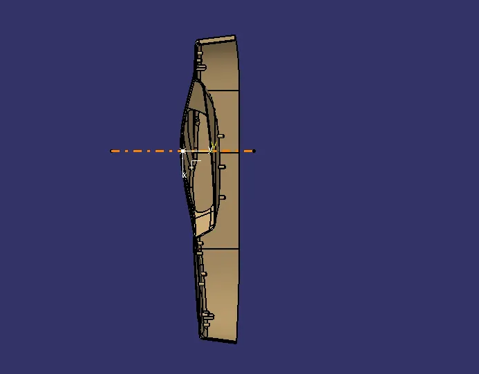
Side View:
Top View:
Thus the solid model is created with close surface method along aith attachments such as locators and heat stakes created and draft analysis is performed.