Week 10 - Challenge 3 - Door Trim Lower with Engineering Features
AIM: Create a DOOR TRIM LOWER plastic component through a given class A surface and also create Heat Stake and Locators on the DOOR TRIM LOWER solid surface.
Objective: In this project i'm going to deal class B and C surface through a given input class A surface using CATIA V5 software. Also create Heat Stake and Locators on the solid surface which is an engineering feature. All the sketch are fully ISO constraint and positioned sketch.
Procedure for Close Surface
- Import Class-A Surface in catia workbench
- Create tooling axis on class A surface
- Do Draft analysis of tooling axis
- Create Class-B Surface
- Create Class-C Surface
- Join Class A and Class C surface
- Trim with Class B and Class A & C joint and
- Make it solid through using close surface tool in part design workbench
Procedure for Locators
- Extract class A surface where we want to fix
- Create sketch along plane which is parallel to the extracted surface
- Sketch should be ISO constraints and positioned sketch
- Pad the sketch
- Give fillets and chamfers
- Add to the main assembly by trim or add command
Procedure for Heat Stakes
- Create sketch for heat stakes
- Sketch should be ISO constraint and positioned sketch
- Pad it appropriate thickness
- Give fillets
- Add to the main assembly
DOOR TRIM LOWER DESIGN
Before going on to the Doror trim design first we will have to create close surface of given input class A surface.
TOOLING AXIS:
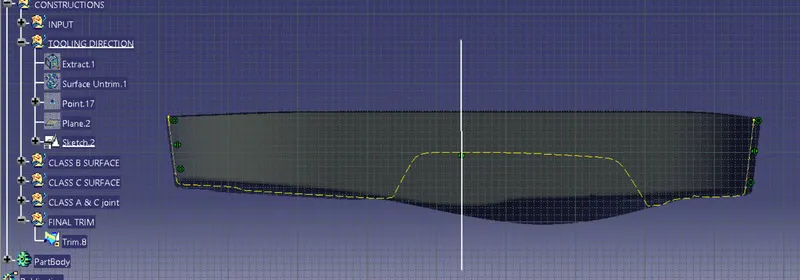
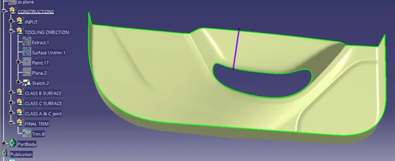
First we have to observe and study the class A surface to create the "Tooling Axis" for the component, and for the above given door trim. Here i use bisecting method to create tooling axis by the use of side wall surface. Initially, I create a point and plane then entered into sketch workbench. Intersect the class A surface by using 3D element and along with the direction of the axis draw a line which is coincide with intersect line then use bisecting two line to create a middle line. Once the middle line we get, rest of the line make construction line. Now analyse tooling axis by analysing draft and class A surface making an angle direction inbetween 0-3 degree by draft analysis.
DRAFT ANALYSIS:
To perform draft analysis, click on Insert>Analysis>Feature Draft Analysis
Once the draft analysis toolbar is opened, go to the display block and select the 'Analysis under the running point' command to check the angle for different sides (walls and inclined plane angles) on the class A surface. The color scale on the bottom visualizes, whether the draft angle meets the requirements or not (3 deg) by indicating the colors Green, Blue and Red. Once the draft angle analysis was done, we need to align and fix the compass to the tooling axis of the class A surface.
To align and fix the compass to the tooling axis, go to the direction block in the draft analysis toolbar and click on the 'Use the compass to define the new current draft direction option (or just click on the compass symbol). Now bring the compass to the surface and align it to the tooling axis of the class A surface and click on the lock symbol beside the compass in the direction block. Once we click on 'ok' on the draft analysis toolbar, we can finish the draft analysis process.
NOTE: First check shading is in material mode (Go to the customise view parameter)
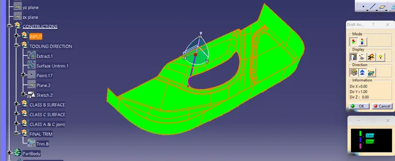
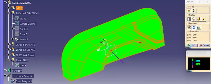
We can clearly see in the above figure draft angle is set to be 3 degree and all the surfaces are in green color it means we can consider tooling axis is now main tooling axis.
CLASS B SURFACE:
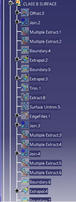
To create the class-B surfeace, I will go through the direct offset method becouse here the given door trim surface are very difficult to find out where to start class-B surface so to do that we have to directly offset it upto desired thickness and then we will go through, like some part are missing in offset surface. So that surface we have to fill by using extraction, untrimmed, extrapolation, trimming, joinning tool in surface design workbench etc.
Here it showing warning that some element or patches are missing so we have to click "OK". Offset value = 2.5mm
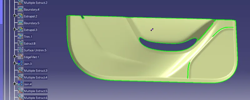
Now remove fillets and extract part and then extrapolate it
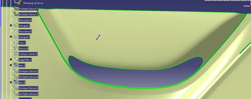
Trim it and give fillet by checking fillet radius
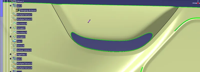
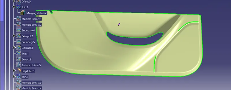
Now move to the second edge fillet, remove fillet by using join-remove subelement
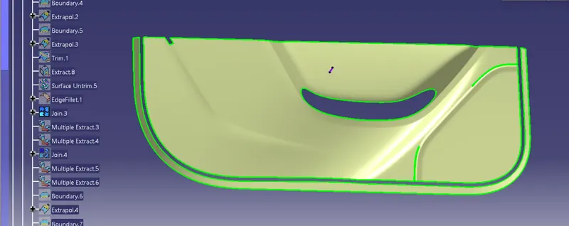
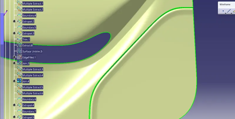
Extract it, untrim them and extrapolate the surface
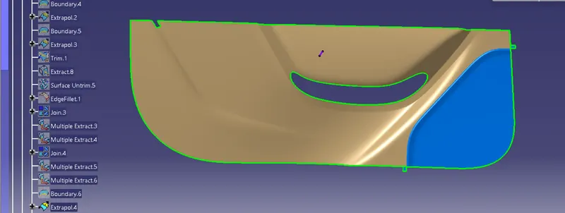
Trim it and give fillet by checking calss A fillet radius and then by calculating of 2.5mm offset also.
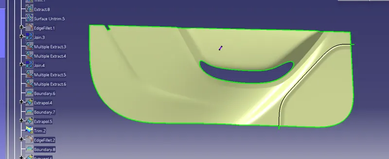
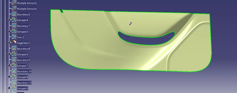
Now by using multi section surface fill the small gap
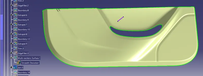
B SURFACE is ready for close surface by using various operation.
CLASS C SURFACE
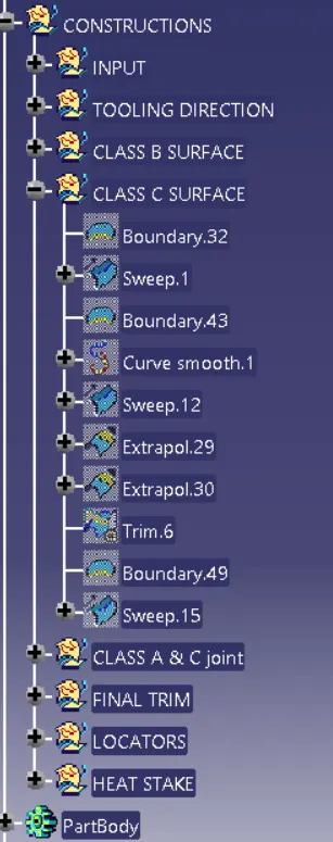
It is the combination of Class A, Class B and Class C surfaces. To create a class C surface, I used the sweep command by considering the outer boundary of the class A surface. In the sweep command, go to the 'line' command in the 'profile' block and the subtype is 'with draft direction'. Now select the outer boundary and tooling axis, give 3 deg in the angle and select the direction to sweep, in this condition the class B surface is under the class A surface so select the inside down arrow to sweep. Now I joined all the sweeped surfaces by using the 'join' command and then I trimmed the Class A, Class B and Class C surfaces to make a closed surface, to make a Solid body.
Boundary creation and Sweep command:
Here we use one by one sweep and boundry command becouse there is sharp edge in the class A.
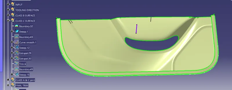
Add another sweep at the other end
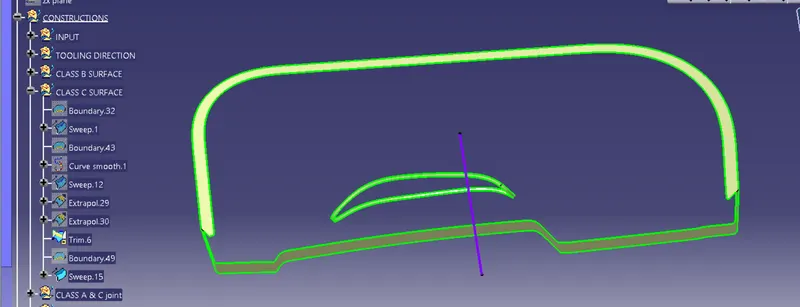
Join class C with class A surface
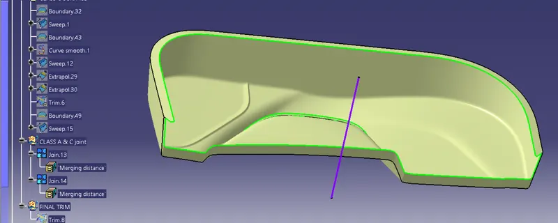
FINAL TRIM Class B with Joined Class A & C
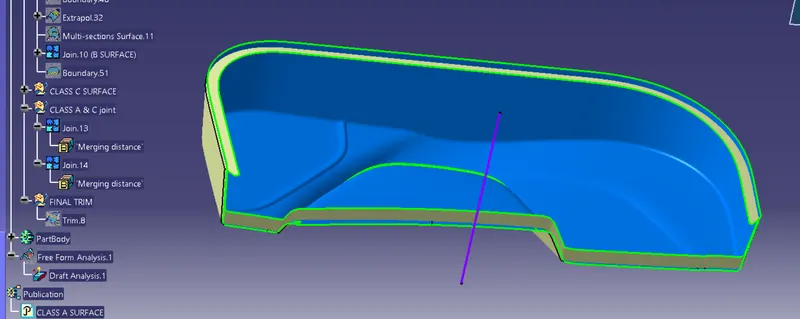
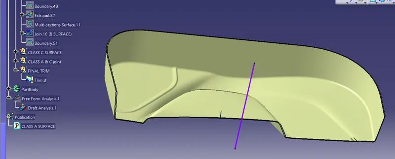
Now we have to check boundry of final trim, below we can clearly see we get error it means final trim is fully connected
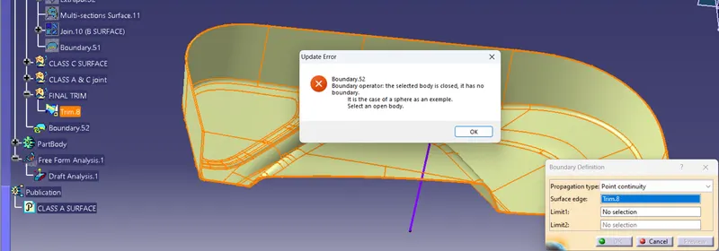
Make it Solid by using close surface
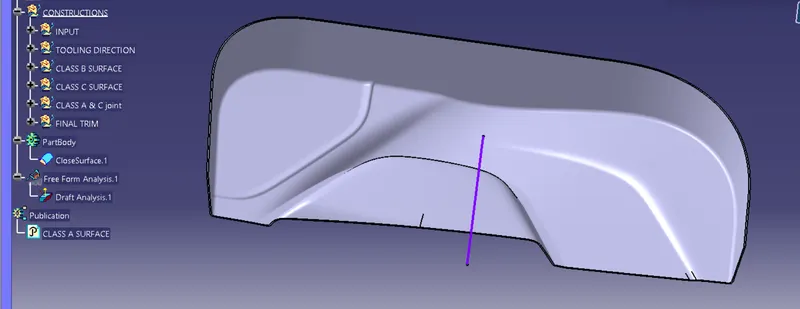
4 WAY LOCATORS
Locators is an engineering feature used in plastic trim design. Locators are used as supporting feature. Sometimes other engineering features like snaps, rib etc. are mounded on them to increase their strength. Locators and other engineering components are built on B-surface.
- 2-WAY LOCATORS: A 2-way locating pin restricts motion along 1 axis (or 2 degrees of Freedom), like a round pin in a slot. Likewise, a 4-way pin restricts 4 degrees of freedom along 2 axes. A round locating pin located concentrically in a hole is a common application of a 4-way pin, and helps to further secure the piece.
- 4-WAY LOCATORS: 4-way means we prevent movement at 2 axes (+X, -X, +Y and -Y) on the plane. Generally, we have cylindrical pin on the fixture and circular hole at workpiece part.
Sketch for locators
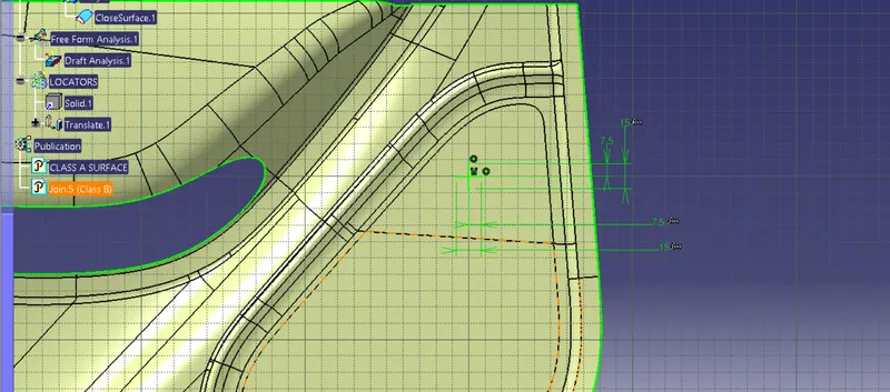
Pad it, draft (0.3mm), provide chamfer(3mm) and edge fillet(0.3mm & 3mm)
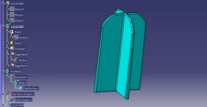
2nd Locators which is by copy paste and then translate according to the desired location
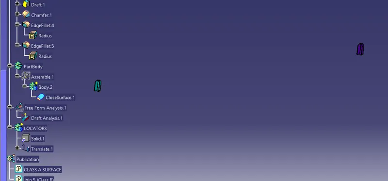
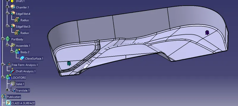
Add these two locators to partbody by using trim command which means unnecessary parts will removed.
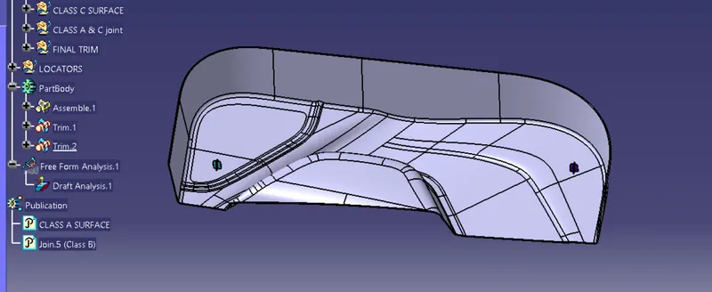
HEAT STAKE:
Manufacturing operations currently use many different combinations of attachment methods to keep components together. Common fasteners such as bolts, screws, and rivets can be used to form permanent attachments, but there are attachment methods that don’t require secondary hardware. One of those methods is heat staking, which doesn’t require additional fasteners.
" Heat staking is the process to attach two separate components together by melting the base plastic material into a shape that will hold the secondary component. It’s a permanent attachment method that does not require any additional material such as an adhesive or a solvent to make the permanent bond. The only addition is the heat applied to melt the plastic and a tool to shape the plastic to form the mechanical connection."
Heat staking can be done with a precise and rapid operation that also offers repeatable results every cycle. Manufacturing machine can be developed to complete multiple heat staking operations at once to decrease cycle time. The stakes don’t have to be parallel which makes the design options limitless.
Heat staking is a great option that is comparable in strength and durability to other operations involving secondary fasteners without extra cost. These connections can also resist corrosion in harsh environments.
Reasons for Heat Staking:
- Mutiple staking shapes for different benefits
- Excellent durability
- No extra materials are needed
- Increased efficiency and
- Easy Maintenance.
Create point and do sketch
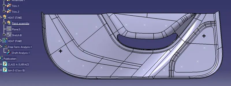
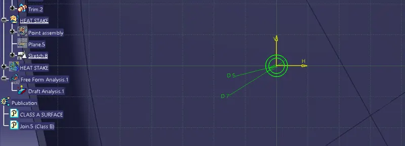
Pad it but hight should be less than locators
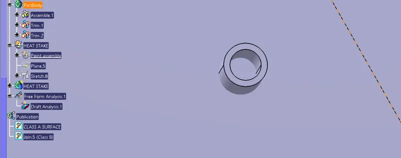
Copy the padding body and paste it into new body and then translate it by using point to point
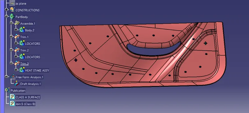
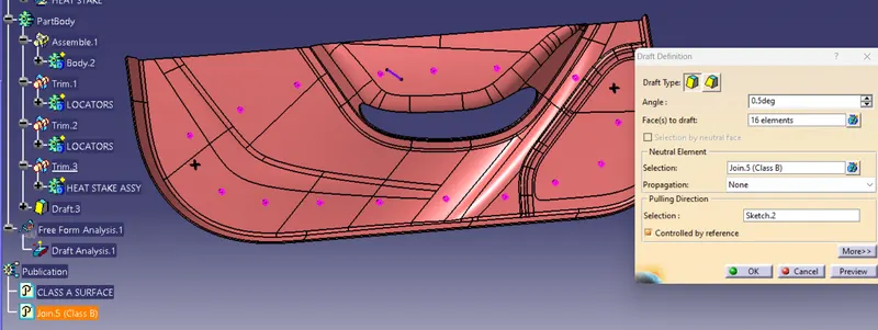
Add draft angle (0.5mm) to the heat stake
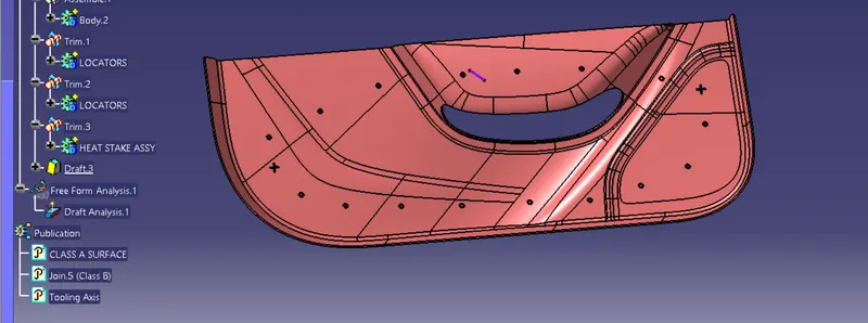
DRAFT ANALYSIS:
Once the draft analysis toolbar is opened, go to the display block and select the 'Analysis under the running point' command to check the angle for different sides (walls and inclined plane angles) on the class A surface. The color scale on the bottom visualizes, whether the draft angle meets the requirements or not (3 deg) by indicating the colors Green, Blue and Red. Once the draft angle analysis was done, we need to align and fix the compass to the tooling axis of the class A surface.
To align and fix the compass to the tooling axis, go to the direction block in the draft analysis toolbar and click on the 'Use the compass to define the new current draft direction option (or just click on the compass symbol). Now bring the compass to the surface and align it to the tooling axis of the class A surface and click on the lock symbol beside the compass in the direction block. Once we click on 'ok' on the draft analysis toolbar, we can finish the draft analysis process.
NOTE: First check shading is in material mode (Go to the customise view parameter)
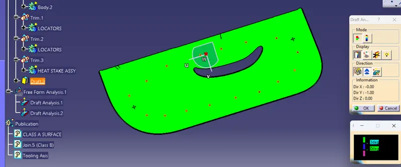
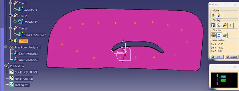
We can clearly see in the above figure draft angle is set to be 3 degree and all the surfaces are in green color it means solid partbody is in correct.
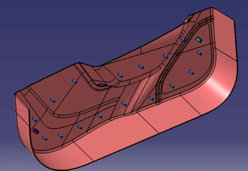
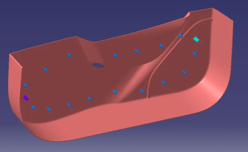
ISOMETRIC VIEW
FRONT VIEW
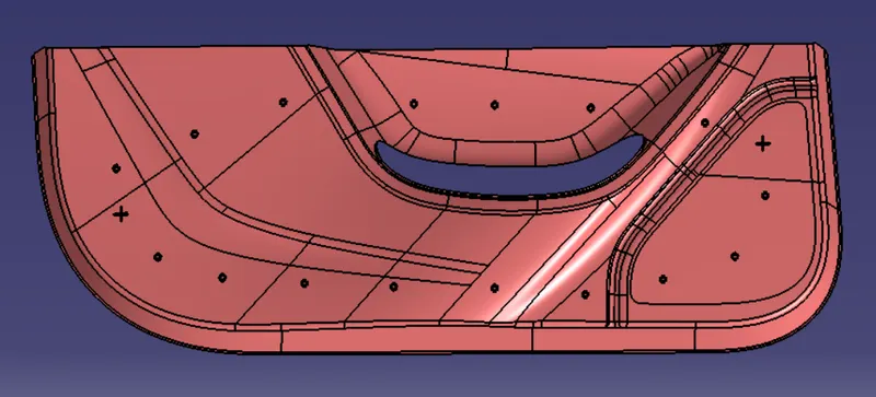
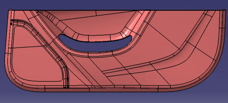
BACK VIEW
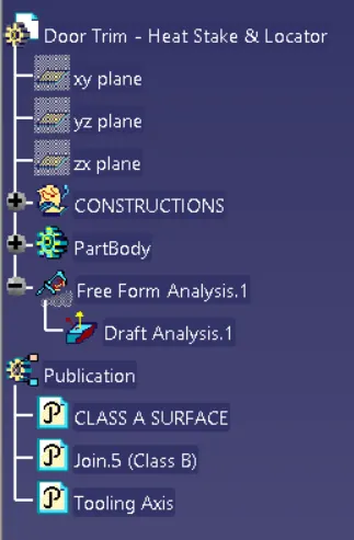
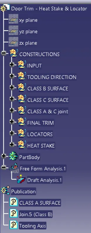
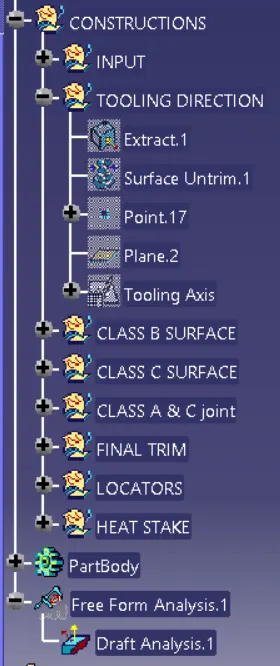
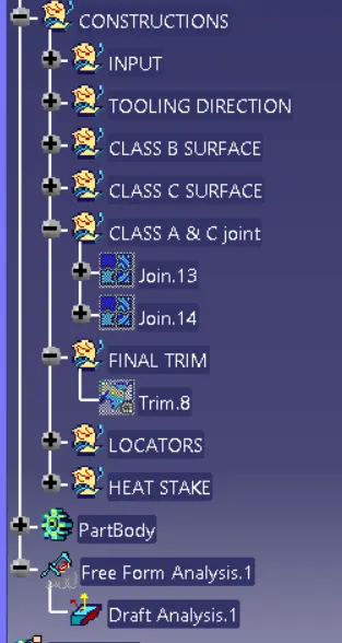
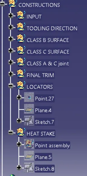
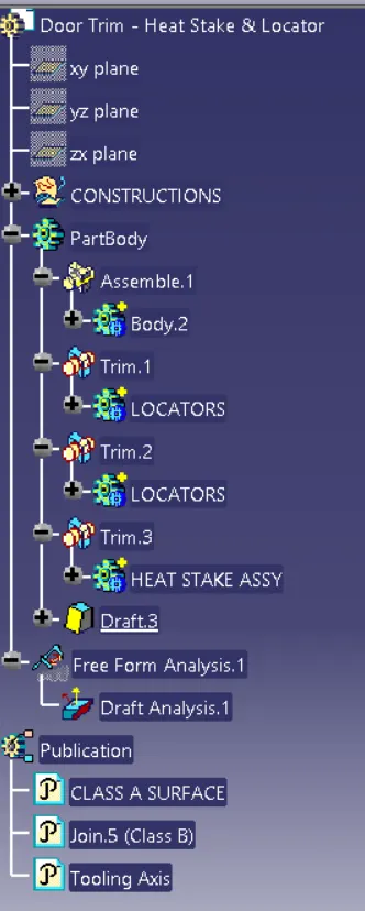
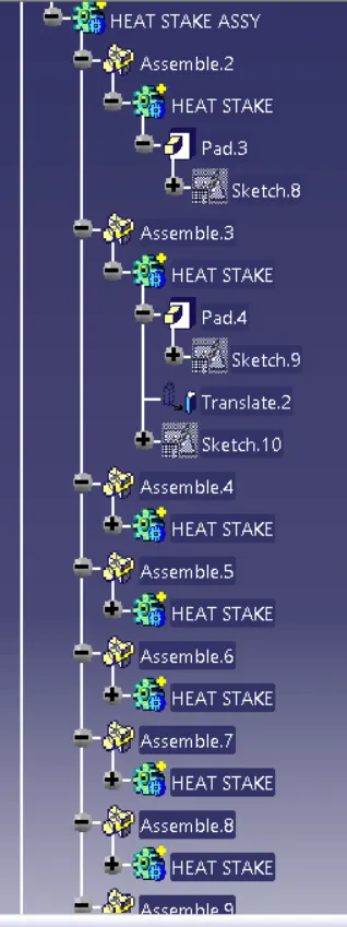
TREE STRUCTURE
CONCLUSION:
Here we studied Heat Stake and Locators where we use different tools in surface design and part design workbench in CATIA V5 software. In this project first we create solid body of given input class A surface and then create locators and Heat Stake on solid body, also analyse the draft.