Week 10 - Challenge 3 - Door Trim Lower with Engineering Features
Door Applique
The door applique class A surface was provided for heat stake and locator design. Before starting modeling the solid plastic model, first thing to ensure is that the surface is free of defects/ flaws. Then the draft analysis is to be carried out.
Draft Analysis:
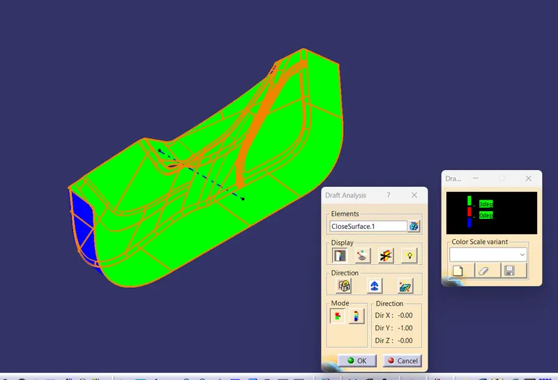
For draft analysis, a tooling direction is to be defined. Clearly the surface can clear the draft analysis with a normal axis. For that a point is created on the surface, somewhat in the middle portion. A line passing through this point in the Y direction (normal direction to surface) is created, which will serve as our tooling axis.Now the draft analysis is done on class A with respect to this tooling axis. The draft analysis result of class A is as follows:
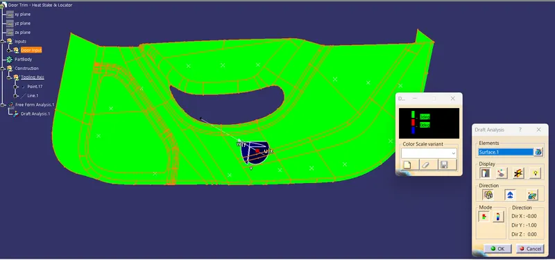
The surface is clearing draft analysis , with 3 degree draft everywhere. Next we have to design the solid plastic model from the given class A surface.
Class B Creation:-
First, the given class A is offsetted to 2.5mm inside.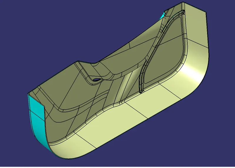
Cyient colour is the class A and yellow coloured is the offsetted surface. This is not final as this new surface several patch corrections to become final class B surface. The patch corrections can be made using multisections, surface fill ....etc. The following operations were made for B surface creation:
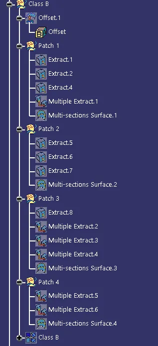
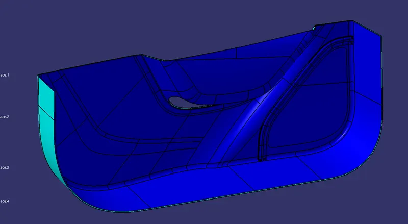
Blue coloured surface is the final B surface, after patch corrections.
Class C creation:
Class C is the surface which connect A and B surfaces and forms a closed surface body. This is created by extracting the boundaries of class A and the sweeping it normal to the surface through this boundary. Here, there is a hole inside. So class C should be created on inside as well as outside boundary of the class A surface.
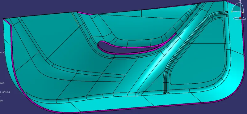
The figure shows class A and C together.
Closed Surface Creation:-
Once the creation of class B and C is over, they have to be joined with class A to form a closed surface. First class A and C is to be joined using join tool. Then, this assembly is to be trimmed with class B to get the output closed surface.
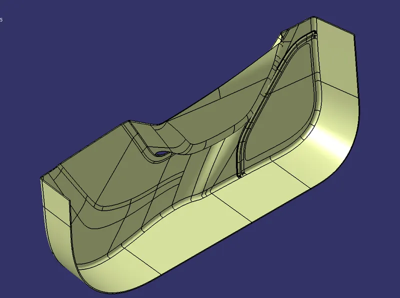
Figure shows the closed surface body.
Solid Model Generation:
After creating the closed surface body, solid body is to be created. This can be done using closed surface feature in part workbench. Figure below shows the solid plastic model, made out of closed surface model:
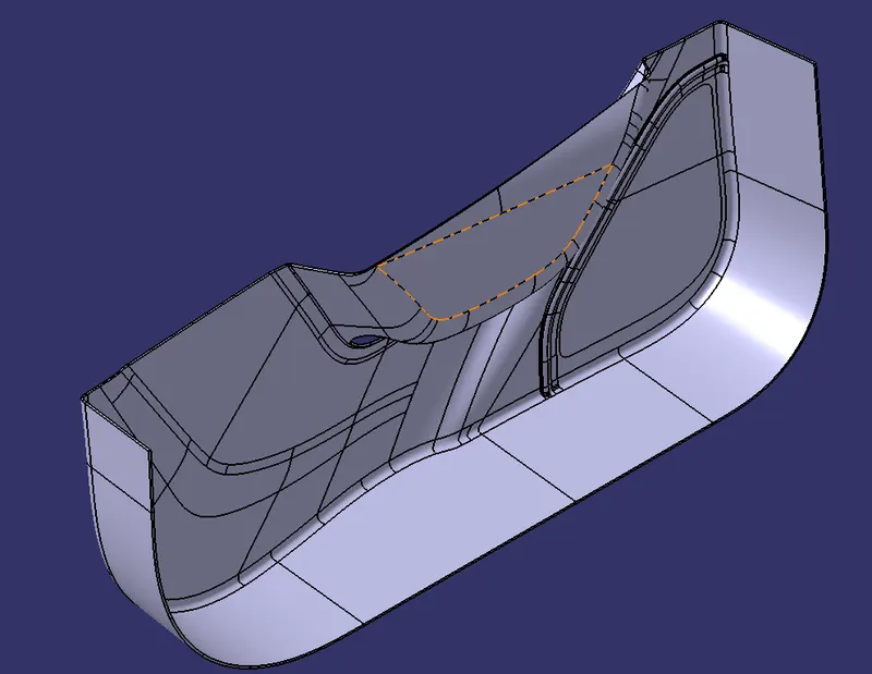
Draft Analysis of Solid Model:
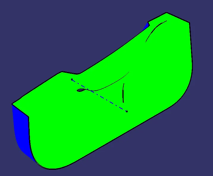
After the creation of solid body, draft analysis of this is to be carried out using the tooling axis. The draft analysis is done and obtained satisfactory output as shown in figure:
Locators and heat stakes creation:
Locators are used for fixing the component at definite points. They are inserts which gets inserted into counterparts. Thermal staking is an assembly method that uses the controlled melting and reforming of a plastic stud or boss to capture or lock another plastic or metal component of an assembly in place.
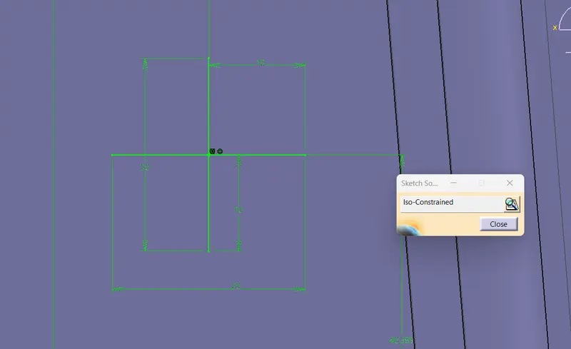
For locators, a cross of lines is made and thickened to 1mm. This is padded to 20mm. The skech is shown below:
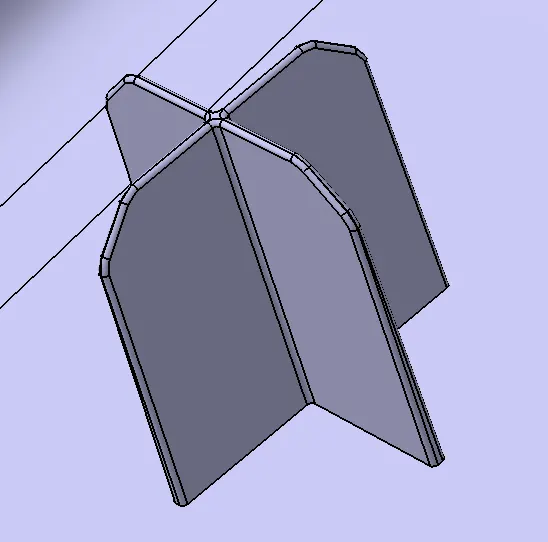
The solid locator is drafted and filleted to satisfy design needs. This is positioned at required points by copy, paste. The solid locator is shown below:
For heat stakes, a hollow cylinder is padded for 15mm and is positioned at required points. The solid model is shown in the below figure:
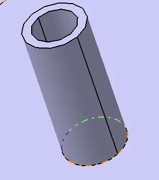
Both locators and heat skates are assembled with main body to form the final product.
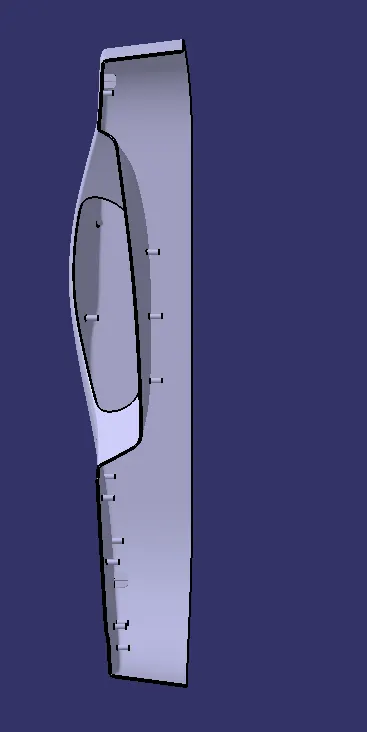
The fifferent views of door applique with engineering features is given below:
Isometric View:
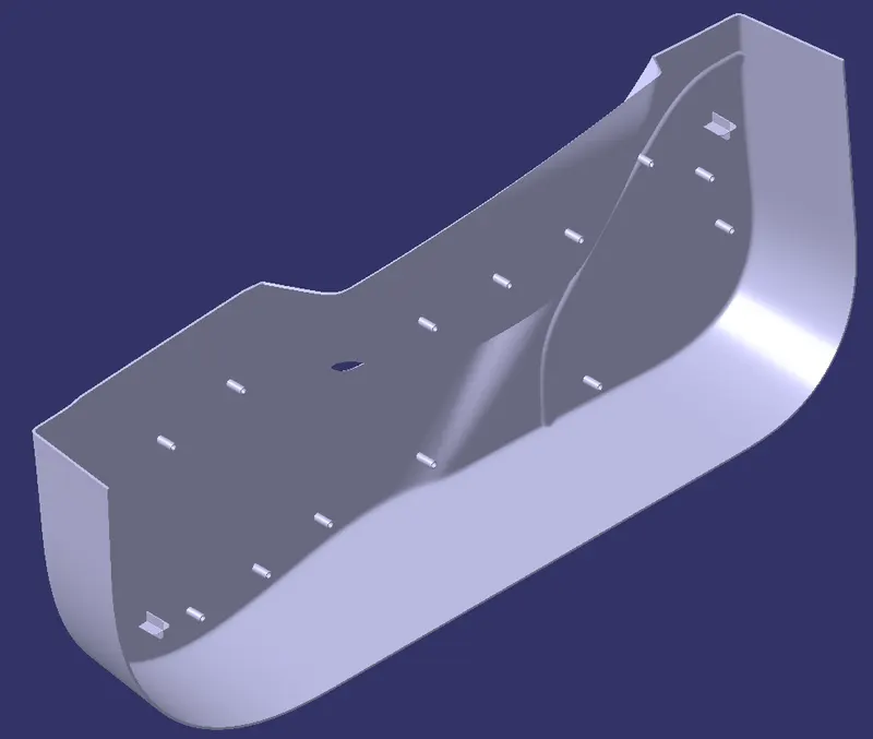
Front View:
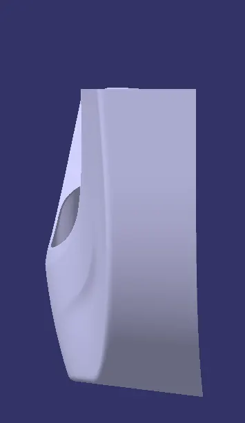
Side View:
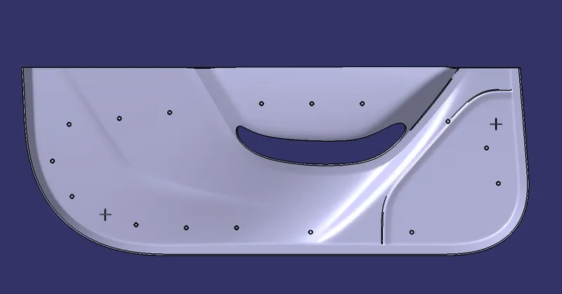
Top View:
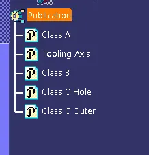
During the design process, some parts were published as given below in figure: