Week 10 - Challenge 3 - Door Trim Lower with Engineering Features
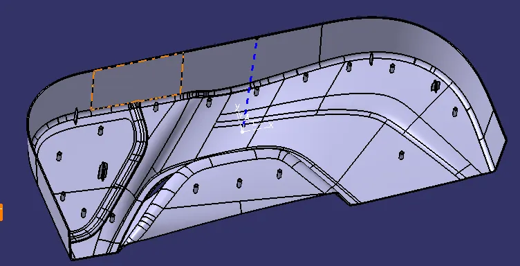
AIM:- To create the door trim with all the engineering features such as Locators and heat stakes by considering all the design rules and performing the draft analysis of the Given class A and final component with all the B side features.
Objective:-
- Create the Tooling axis.
- Design the class-B and class-C surfaces and join them.
- Use the Close Surface feature to make a solid body from the surface.
- Design the required LOCATORS AND HEAT STAKES and analyze them.
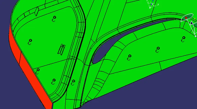
- Perform the Draft analysis for the final component.
GIVEN CLASS A SURFACE:-
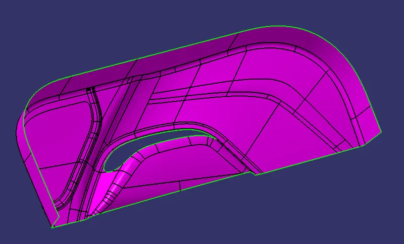
TOOLING AXIS:
The tooling Axis is the direction of the Mold opening and closing and after creating the Tooling axis, I performed a draft analysis for class A to check the draft angle for it.
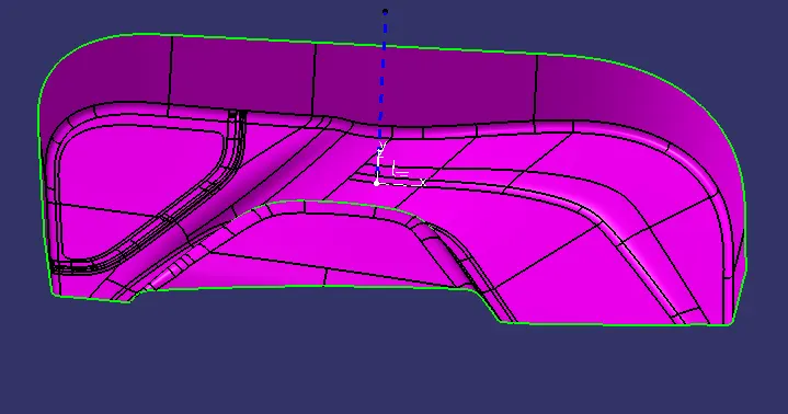
Draft analysis for class A surface:
To perform the draft analysis in class A, I selected the featured draft analysis tool in the Generative shape design workbench. Initially, I click on the 'use of the compass to define the new current draft direction' command to align the compass to the tooling axis.
Once the compass is aligned the compass to the tooling axis, we need to select the surface to perform draft analysis. Class A surface will be highlighted (in green color) according to the color bar angle and colors we defined in it.
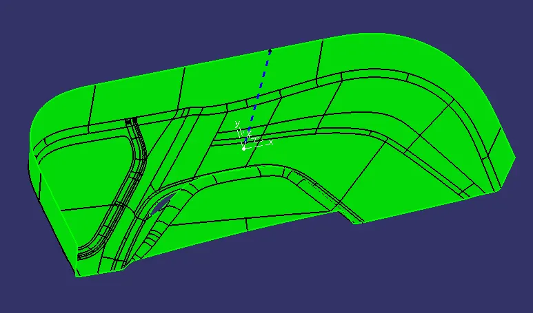
CREATION OF CLASS B SURFACE:
In this component Creation of the class B surface first, we must offset the entire model by 2.5mm outward some of the surfaces give offset error and ask for offset without these sub-elements click okay and work on the incomplete surfaces by using the multi-section surface command, sweep and different commands used to complete the class B surface.
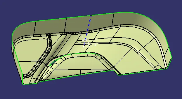
CREATION OF CLASS C SURFACE:
By using the Sweep command, we create the Class C surface in the number of patches and join them at last.
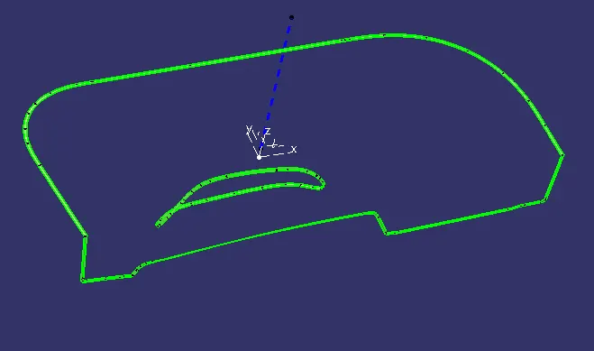
CREATION OF CLASS A+C SURFACE:
By using the Join command, we join Class A & C together.
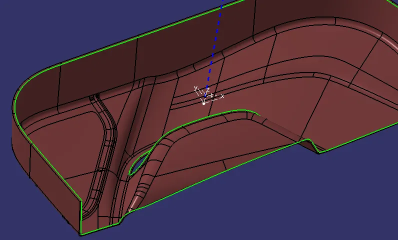
Then trim the class-B surface to join (A+C) this will make sure that we get a closed surface. We can check it using the boundary tool, if it gives an error that means that the component is closed.
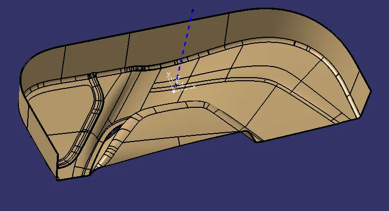
Then We go to the part design workbench and use to closed surface tool to create a solid body.
hence, we created our final Solid component.
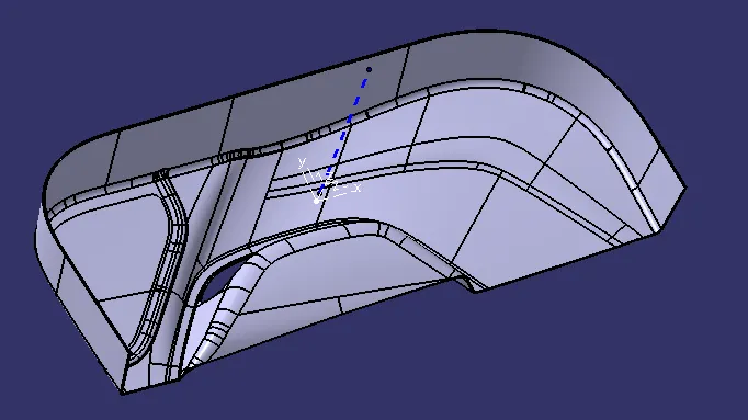
B-SIDE FEATURES DESIGN:-
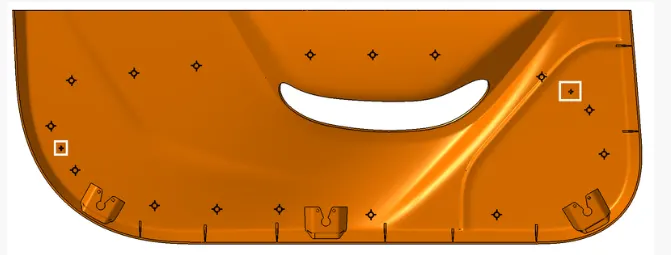
WE NEED TO DESIGN FOUR-WAY LOCATORS, TWO-WAY LOCATORS & HEAT STAKES AS PER THE DESIGN STANDARDS AND THE LOCATION AS PER BELOW GIVEN PICTURES
FOUR WAYS & TWO-WAY LOCATORS:-
Locators are one of the most important B-side features used to locate the parts during assembly. locators help in aligning the two mating components so that the fixation can be accurate and error-free because it arrests the degree of freedom of the component. locators generally arrest the rotational and linear degree of freedom of the component. One of the important things is that all the locators should be at the same height so that the first locators come in contact with the mating part.
HEAT STAKING:-
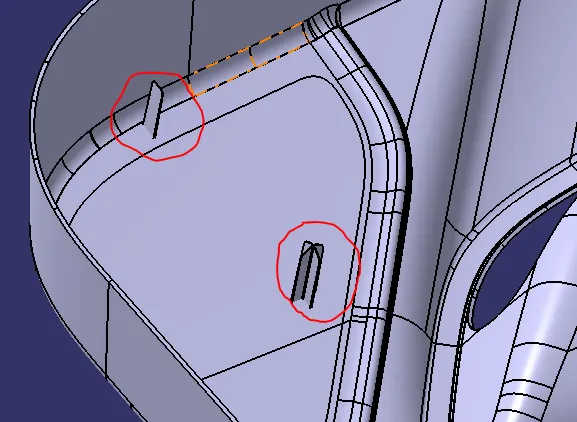
Thermal heat stacking is an assembly method that uses controlled melting & reforming of a plastic stud or boss to capture or lock another plastic or metal component of an assembly in place. The plastic Stud Protrudes through a hole in the component to be locked in place. The heated thermal tip comes in contact with the top of the stud, which melts and fills the volume of the tip cavity to produce a head, locking the components in place.
there are some advantages of heat stacking:-
1. Simplification of Machinery.
2. Reduced cost of Machinery.
3. Multiple fastening Points.
4. Allows higher density of welds as compared with hot air or ultrasonic welding.
DRAFT ANALYSIS OF THE FINAL COMPONENT WITH ALL B-SDIE ENGINEERING FEATURES:-
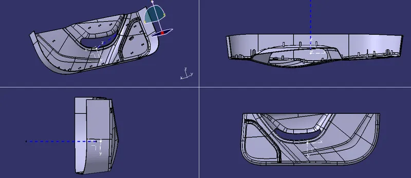
ALL THE VIEWS OF THE COMPONENT: -
Conclusion:
Hence, LOCATORS AND HEAT STAKES for the door trim were created by considering the design rules, and the Draft analysis performed on the final component is successfully done.