Photo Realistic Rendering
- Title of the Project – Modelling & Assembly of American chopper and Photorealistic rendering.
- Objective-
- To Model each part of the chopper in solid work.
- To assemble all the parts of the chopper in the assembly workbench using Appropriate mates.
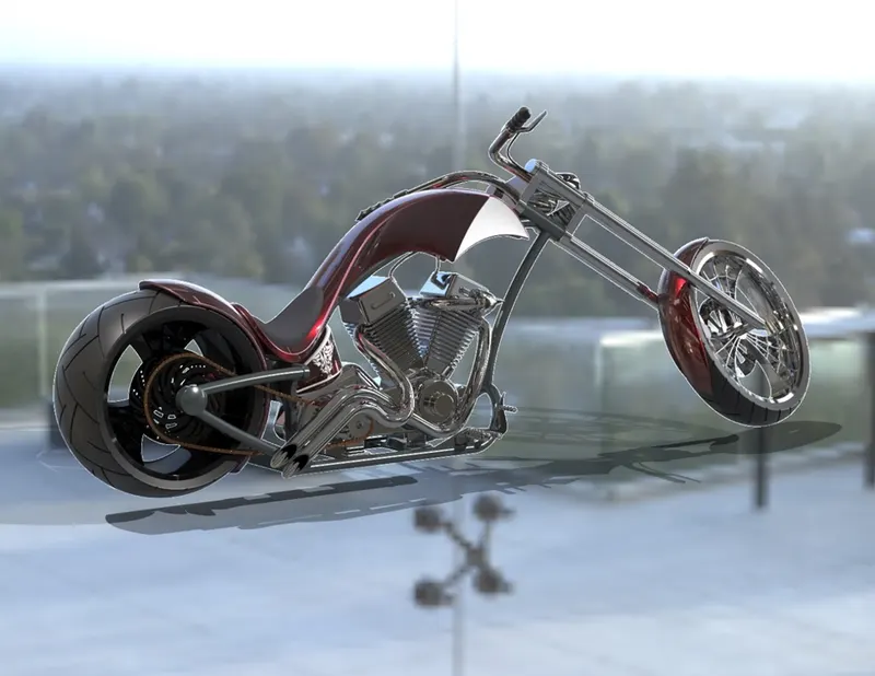
- Photo Realistic Rendering of the American chopper in the real environment.
- Introduction – This is all about the Modelling of American Chopper, which is elaborated in detailed form along with the approach followed to develop this model.
4. Design methodology/approach –
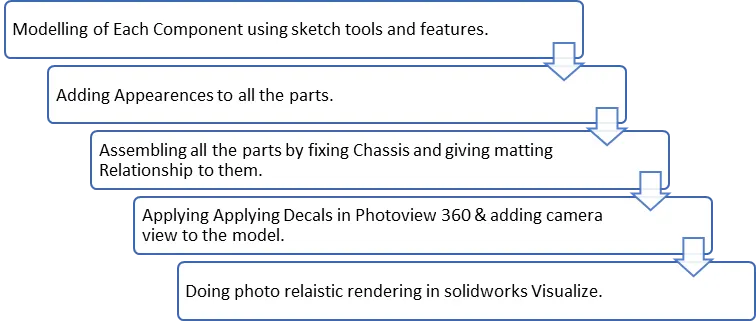
5. Description-
- Transmission Belt- Transmission belt is used to transmit power from the engine to the rear wheel.
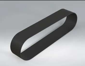
Transmission belt rendered Image
Features used to create Transmission Belt-
- Sketch
- Offset
- Extrude
- Fillet
- Chassis-The chassis is the most important part of the vehicle Which holds the Engine, Rear wheel, front wheel, and most other parts of the vehicle.
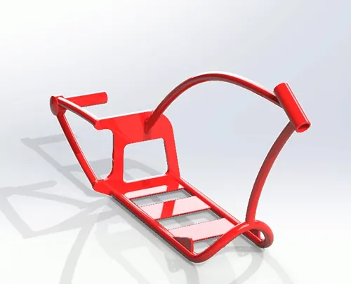
Chassis Rendered Image
Features used to create Transmission Belt-
- Line
- Circle
- Arc
- Extruded Boss
- Swept Boss
- Extruded Cut
- Split
- Fillet & Chamfer
- Dome
- Spline
- Mirror
- Combine
- Intersection curve
- Reference Plane
- Projected Curve
- Engine- The engine is the powerhouse of the Vehicle which Coverts Heat energy to mechanical energy which is transferred to the wheel with the help of a Transmission belt and chain.
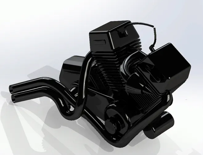
Rendered image of engine
Features used to create Engine-
- Line
- Circle
- Arc
- Convert entities.
- Extruded Boss
- Swept Boss
- Revolve Boss.
- Extruded Cut
- Split
- Fillet & Chamfer
- Dome
- Spline
- Mirror
- Linear Pattern.
- Circular Pattern.
- Combine
- Intersection curve
- Reference Plane
- Projected Curve
- Front & Rear Wheel- Wheels is the circular part of the vehicle which is attached to the front & back of the chassis used to carry a vehicle from one place to another.
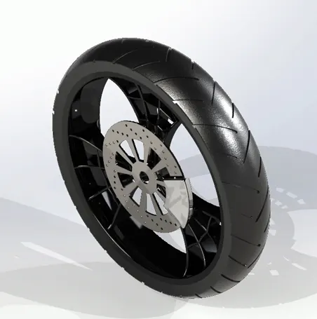
Rendered Image of Front Wheel
Features used to Create Wheels-
- Line
- Circle
- Arc
- Convert entities.
- Offset entities.
- Extruded Boss
- Revolve Boss.
- Extruded Cut
- Fillet & Chamfer
- Spline
- Linear Pattern.
- Circular Pattern.
- Combine
- Intersection curve
- Front Fender & Rear Fender- Fenders are located about the Wheels In order to protect the rider from dust, dirty waters, and other harmful particles which encounter wheels while riding.
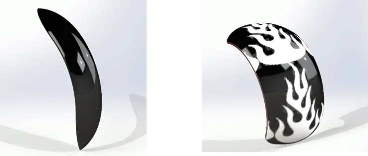
Rendered Image of Front Fender Rendered Image of Rear Fender
Features used to Create Fender-
- Line
- Circle
- Arc
- Split
- fillet
- Revolved Boss.
- Spline
- Front Fork- Front Fork is attached to the Chassis and holds the Wheel on it.
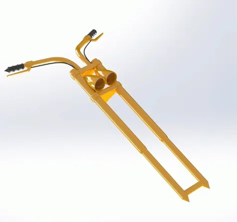
Rendered Image of the front fork
Features used to Create Front fork-
- Line
- Circle
- Arc
- Covert Entities
- Extruded boss
- Revolved Boss.
- Combine
- Extruded cut
- Swept boss
- Mirror
- Spline
- Dome
- Intersection Curve
- Composite curve
- Linear Pattern
- Reference Plane
- Gas Tank- Gas tank is the fuel tank that is used to store the fuel.
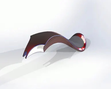
Rendered Image of Gas tank
Features used to Create Gas tank-
- Line
- Spline
- Extruded Boss
- Surface loft
- Surface Knit
- Surface Sweep
- Boundary Surface
- Cut Sweep
- Shell
- Mirror
- Split
- Fillet
- Reference plane
- Oil tank- It is used to Store the oil Which is used by the engine for lubrication.
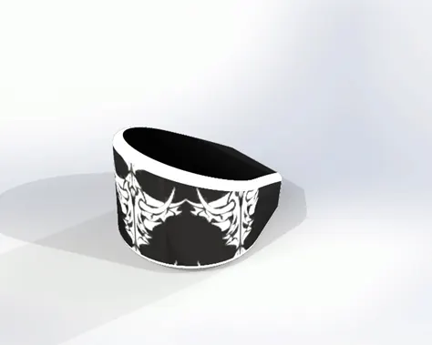
Rendered Image of an Oil tank
Features used to Create Oil tank-
- Line
- Spline
- Extruded Boss
- Shell
- Split
- Fillet
- Combine
- Pedal- It is attached to the chassis, and it is used to place the leg on it while riding the bike.
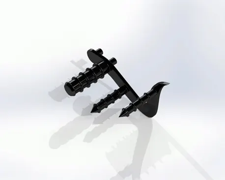
Rendered Image of Pedal
Features used to Create Pedal-
- Line
- Circle
- Spline
- Mirror
- Arc
- Dome
- Extruded boss
- Revolve boss
- Linear pattern
- Combine
- Fillet & chamfer
- Chain- Chain plays the role of transferring power from the engine to the rear wheel.
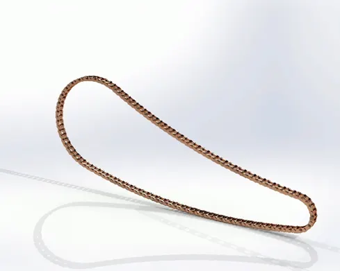
Rendered image of chain
Features used to Create Chain-
- Line
- Circle
- Spline
- Mirror
- Arc
- Block
- Combine
- Fillet
- Curve pattern
- Extruded boss
- Kickstand- Kickstand is the part that is attached to the chassis and supports the bike to stand in non-running condition.
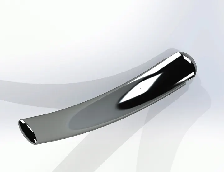
Rendered image of kick stand
Features used to Create Kick stand-
- Line
- Circle
- Spline
- Mirror
- Arc
- Block
- Combine
- Fillet
- Curve pattern
- Extruded boss
- Assembly and Rendering of a chopper-
- Front of Chopper view
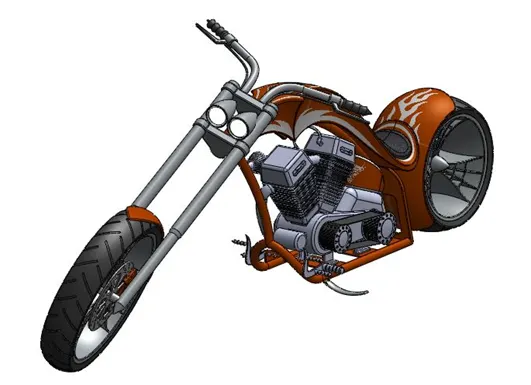
2. Front view of Chopper
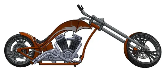
3. Side view of the chopper-
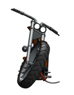
4. Backside view of the chopper-
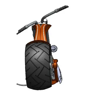
5. Rendered photo camera view in photo view 360-
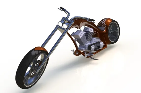
6. Rendered in photo view 360-
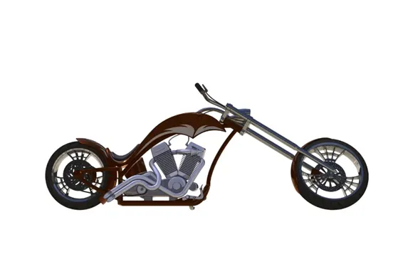
- Rendering in Solid works Visualize with Environment
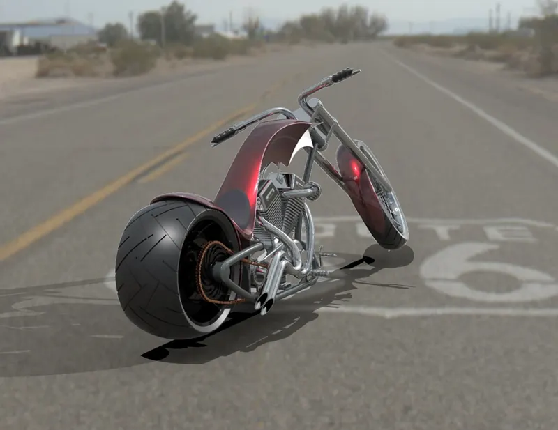
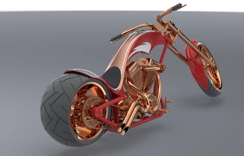
- Conclusion- In this project, we have modeled each and every part of the chopper in solid works and combined them in the assembly workbench and to get a realistic image we have done rendering In photo view 360 and SolidWorks Visualize.