Week 10 - Challenge 3 - Door Trim Lower with Engineering Features
AIM: -
- Create the Door Trim Lower Plastic component through the given Class-A surface.
- Create the Heat Stakes and the locators considering the design rules.
OBJECTIVE: -
- The tooling axis for the given Class-A Surface.
- Perform the Draft Analysis on the Class-A surface.
- Create CLASS-B and CLASS-C Surface.
- Create Heat Stakes and Locators.
- Perform the Draft analysis on the model.
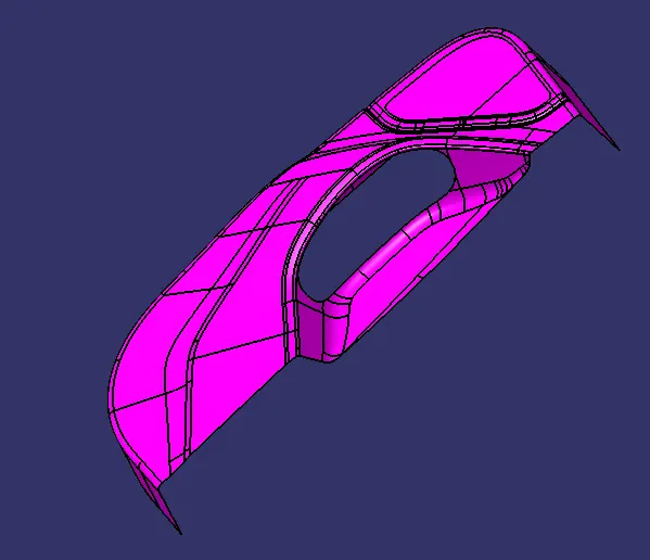
GIVEN CLASS-A SURFACE
CREATION OF TOOLING AXIS
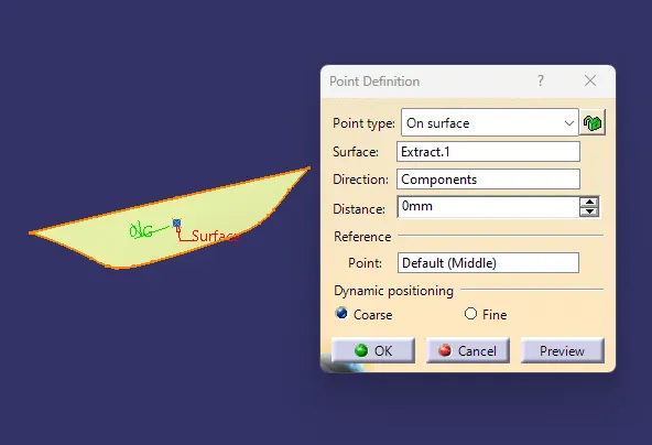
- I extracted a surface from class A to make the tooling axis.
- Using the point command, I made a point in the centre of the surface.
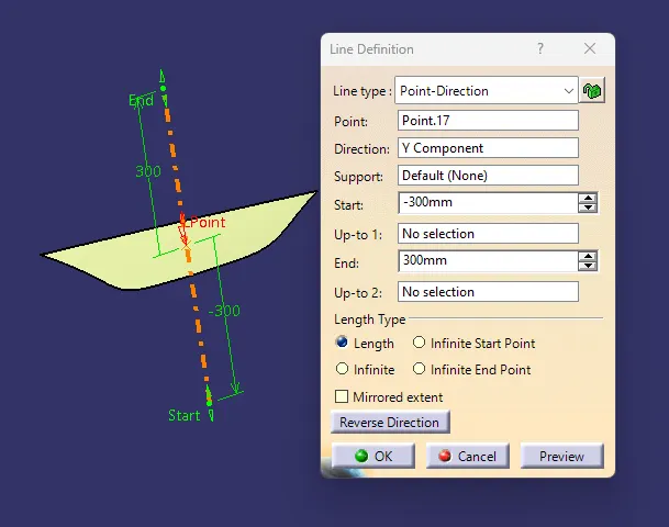
- At that moment, I drew a line through the x-axis.
DRAFT ANALYSIS OF CLASS-A SURFACE
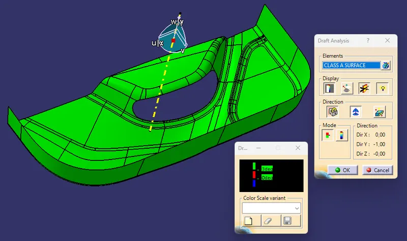
- Before we produce a solid and create B-side features, we do a draft analysis check on the class A surface.
- I started by aligning the compass to the tooling axis and giving the green colour in the colour bar a 3deg draft angle.
- If the surface is indicated in green, the draft angle for a class A surface is correctly represented.
- If the class A surface is not entirely highlighted in green, this might be the cause of the draft angle of the class A surface.
CREATION OF CLASS-B SURFACE
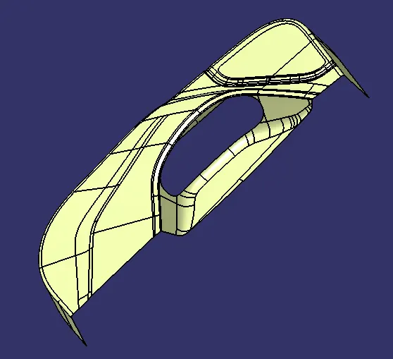
- To make the class B surface, offset the class A surface inside to the required thickness (here, 2.5mm, so I offset the class A to 2.5mm inside).
- When the offset is generated, we can see certain patches on the offset surface by taking the offset surface's border; those patches are made by the fillets on the class A surface.
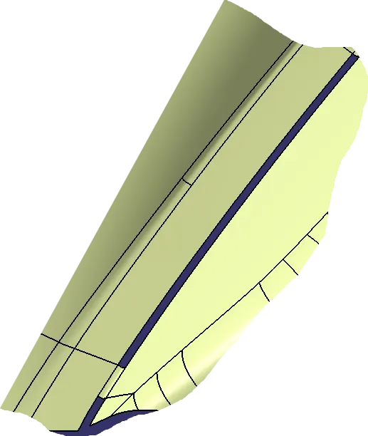
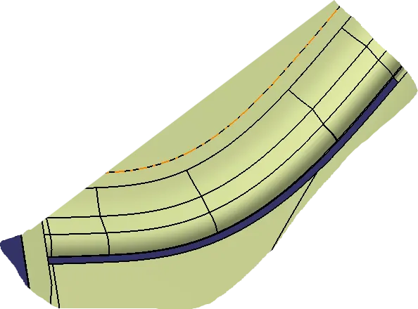
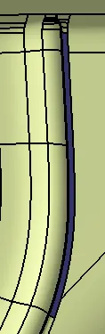
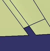
PATCH 1 PATCH 2 PATCH 3 PATCH 4
- We must use the multi-section surfaces command to cover those patches by extracting the patch borders.
- Once all of the patches on the offset have been correctly covered, combine all of the patches with the offset surface to obtain the class A surface's duplicated surface.
CREATION OF CLASS-C SURFACE
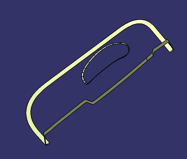
- I first extracted the boundary of the class A surface with tangent continuity.
- Then, I swept the extracted boundary over the surface at 87 (for draught angle) for 10mm to appropriately meet the class B surface.
- I used the sweep command to build the class C surface adjacent to the class A surface's border.
CREATION OF SOLID BODY
- Extrapolate all of CLASS A's surface bounds, extrapolate the sweeped surfaces until both surfaces intersect appropriately, and trim them to eliminate stretched extrapolated surfaces to achieve a good sweep boundary over the full surface, including the door trim's centre hole.
- Join both the class A and the sweep border to obtain the whole class C surface.
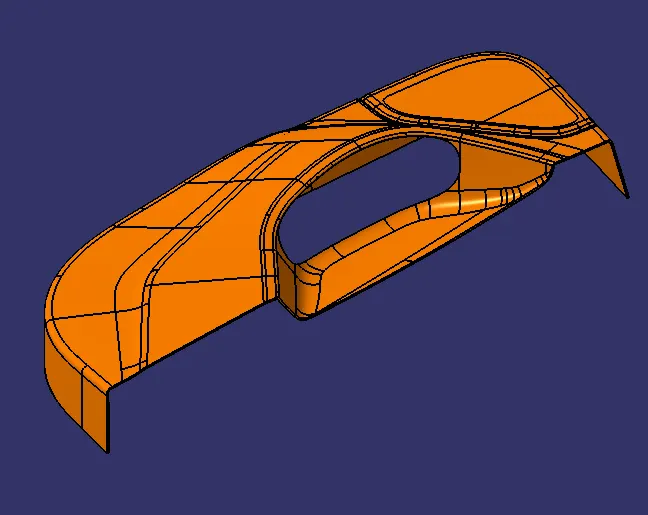
- Unhide the class B and C surfaces now. To obtain a closed surface by trimming class B and class C surfaces, ensure that all of the sides of class B and class C surfaces meet appropriately.
- If the class B and class C sides do not connect appropriately, we must extrapolate the class B surface sides that do not overlap with the class C surface.
- Check the surface limits of class B and class C to see if all of the sides meet or not.
- Trim the surfaces together once they have intersected appropriately to create a closed surface.
CREATION OF LOCATOR
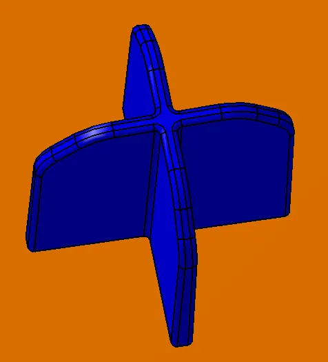
1. FOUR-WAY LOCATOR
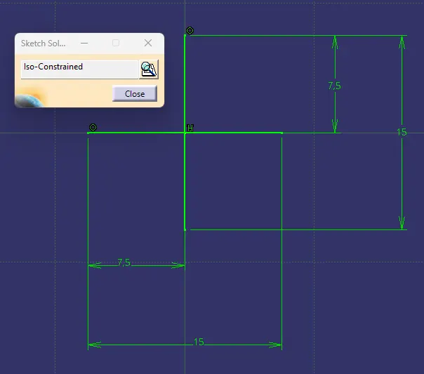
- Using a sketch on the body, make a 4-way locator.
- After you've created the sketch, pad it 20mm in height, thickness it to 1.3mm, then draught it with a 0.5deg angle in the direction of the tooling axis.
- Give a 3mm chamfer with a 45deg inclination and a 0.20mm radius fillet.
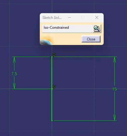
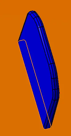
2. TWO-WAY LOCATOR
- Using a drawing on the body, make a 2-way locator.
- After you've created the sketch, pad it 20mm in height, thickness it to 1.3mm, then draught it with a 0.5deg angle in the direction of the tooling axis.
- Give a 5mm chamfer with a 45deg inclination and a 0.20mm radius fillet.
CREATION OF HEAT STAKES
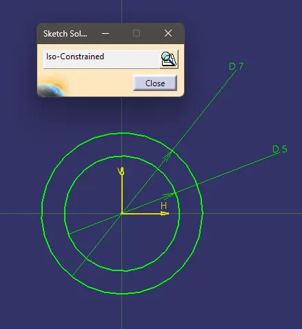
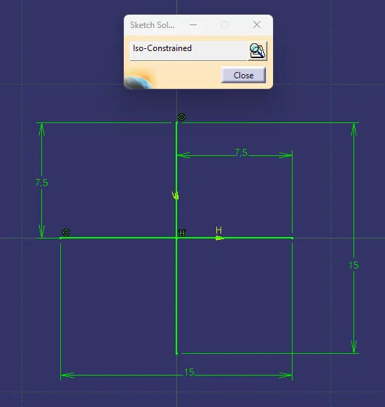
- I draw a sketch on the surface to make the heat stakes.
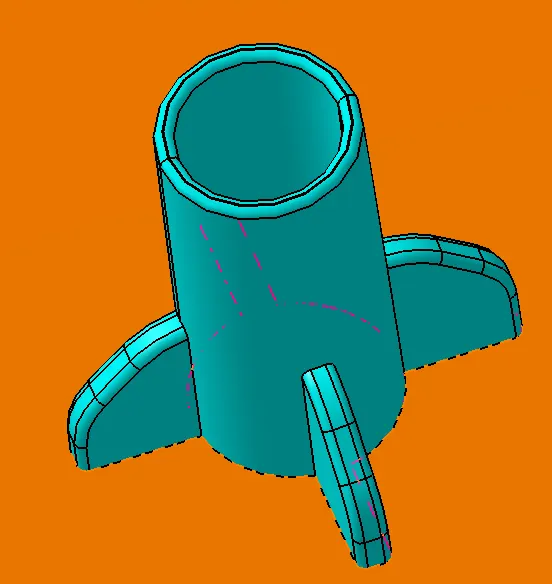
- After creating the sketch, I padded it to 15mm height, gave it a 0.5deg draught angle on both sides (inside and outside), and then a 0.25mm radius fillet.
- I made the ribs to support the heat stake after I finished the heat stake.
- I drew a sketch and padded it to 6mm in height and 1mm in thickness to make the ribs.
- I sketched 0.5deg in the tooling axis direction after cushioning the ribs and filleted it with a 0.25mm radius.
- Finally, I union trim the ribs with a heat stake to eliminate the ribs found inside the heat stakes.
- Now, I translated the heat stakes by copy-pasting them into the component body as needed.
CREATION OF FINAL BODY
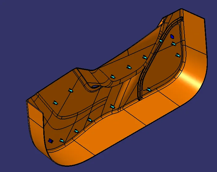
- Now, Union Trim locator and Heat Stakes with solid.
- The final portion body has 4-way and 2-way locators, as well as all of the heat stakes and supporting ribs.
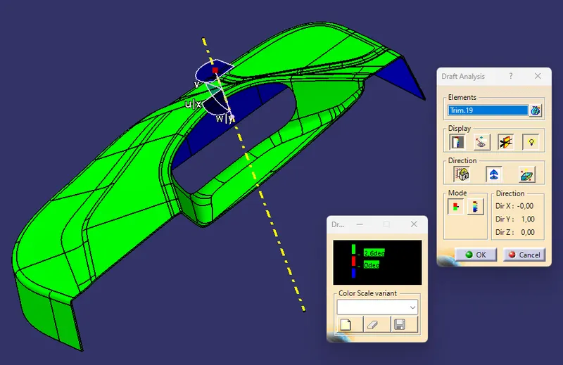
DRAFT ANALYSIS OF THE FINAL BODY
Screenshots of the completed design in various orientations (Isometric, Front, Side, and Top View)
FRONT VIEW
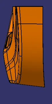
RIGHT HAND SIDE VIEW
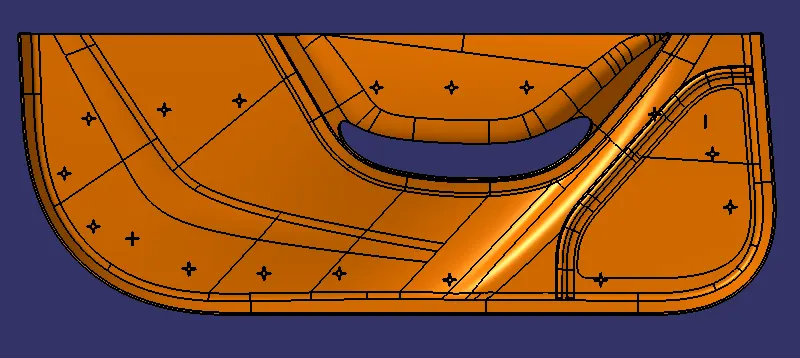
LEFT HAND SIDE VIEW
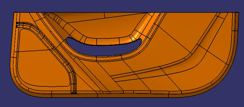
TOP VIEW
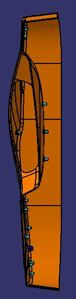
ISOMETRIC VIEW