Week 10 - Challenge 3 - Door Trim Lower with Engineering Features
Class A Boundary Check
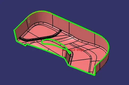
Tooling Axis
I used the point command to make a point in the centre of the surface and then generated a line passing across the x-axis at that point to establish the tooling axis. I then carried out a draught analysis check along that line to determine whether the tooling axis that was established was in the proper location. If the tooling axis is in the proper position and direction on both sides of the area shown with green in the draught, analyse the surface.
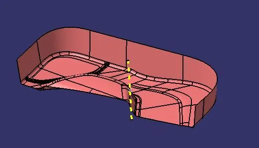
Class A Draft Analysis
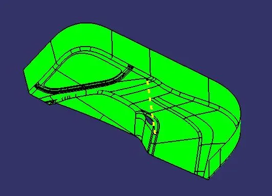
Before we produce solid and create B-side features, we run the draft analysis check for class A surfaces. I then set the compass to the tooling axis and I gave the green hue in the colour bar a 3-degree draft angle. The draft angle is properly given for class A surface if the surface is indicated in green. The class A surface's draft angle may be caused by the fact that it is not completely indicated in green.
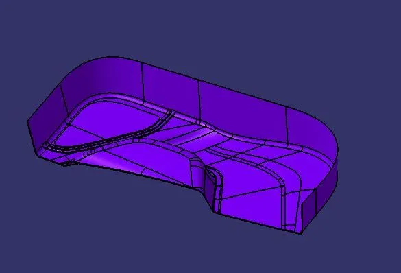
Class B Surface
The class A surface should be offset to the interior according to the required thickness (in this case, 2.5 mm), in order to form the class B surface. By taking the boundary for the offset surface, we can see some patches on the offset surface after the offset has been constructed; these patches are the result of fillets on the class A surface. Using the multi-section surfaces command and patch boundary extraction, we must cover those patches. To obtain the replicated surface of the class A surface, link all the patches with the offset surface once all the patches on the offset have been appropriately covered.
Class C Surface
Regarding the edge of the class A surface, I created the class C surface using the sweep command. To appropriately intersect the class B surface, I first removed the boundary of the class A surface with tangent continuity and swept it for 4 millimetres at a surface angle of 90 degrees (for draft angle). To achieve a good sweep boundary throughout the whole surface, including the centre hole of the door trim, we sweep all of the surface boundaries of class A, extrapolate the swept surfaces until both surfaces properly connect and then trim them to remove extended extrapolated surfaces. To obtain the entire class C surface, combine the sweep border and class A.
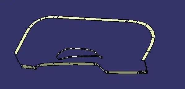
Class A+C Surface
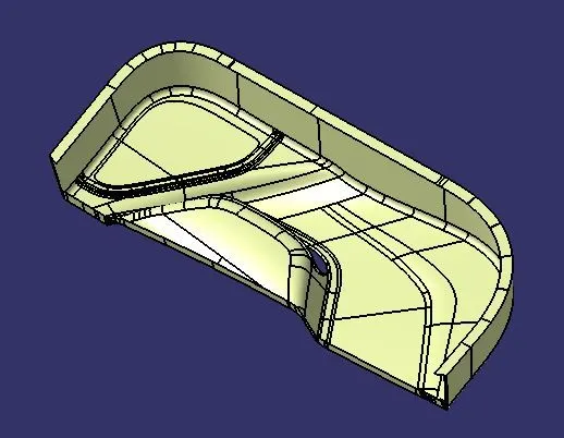
Closed Surface
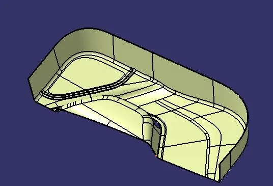
4 Way Locator
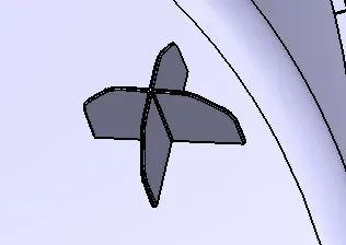
I drew a sketch of the body to use as the locator. After making the sketch, I gave it an 18mm height padding, made it 1 mm thick, and drew a 0.5deg draft in the tooling axis direction. I applied a 7mm chamfer at a 45deg angle, followed by a 0.3mm radius fillet.
Creation of Heat Stakes
To create the heat stakes, I draw a sketch on the surface. After the creation of the sketch, I pad it to 15mm height and gave a draft angle of 0.5deg on both sides (inside and outside) and then I gave a fillet. After creating the heat stake, I created the ribs for supporting purposes. To create the ribs, I draw a sketch and padded it to 10 mm in height and 1mm in thickness. After padding the ribs, I drafted 0.5deg in the tooling axis direction and filleted it with a 0.25mm radius. Finally, I union trim the ribs with a heat stake to remove the ribs, which are present inside the heat stakes.
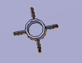
Now I translated the heat stakes and 4-way locators by copy-pasting them in the part body according to the requirement.
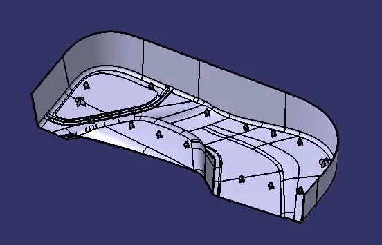
Front View
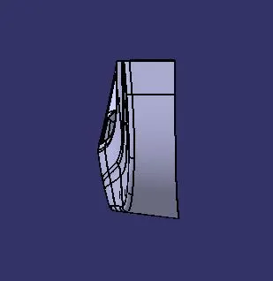
Side View
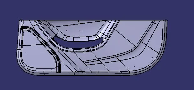
Top View
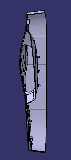
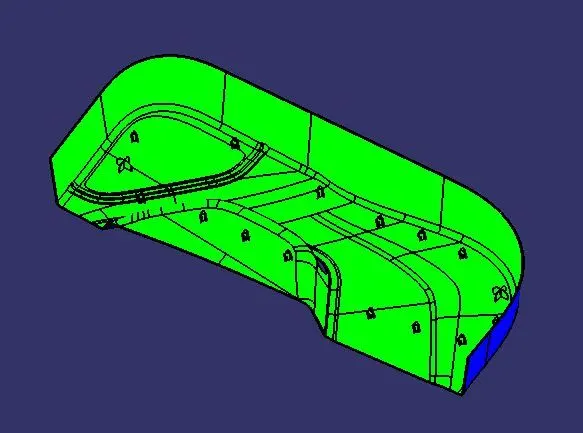
Draft Analysis of Closed body with 4-way locators and heat stakes
Conclusion
Thus by following the above we crate the door trim with B-class features (heat stake and locator pins).