Week 10 - Challenge 3 - Door Trim Lower with Engineering Features
Door Trim Lower with Engineering Features design heat stakes and the locator's design considering the design rules.
AIM: Create the Door Trim Lower Plastic component through the given Class-A surface. To begin with, the tooling axis for the given Class-A Surface should be created meeting the draft angle requirements and performing the draft analysis on the model at the end.
Design the Heat Stakes and the locators considering the design rules.
Class A surface:
This is the styling surface that provides the aesthetic features of a component. A designer starts the design of component by given class A surface.
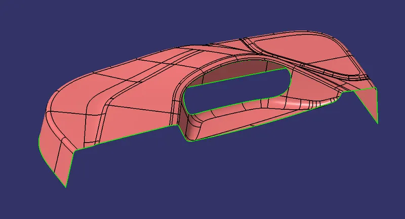
The initial step is to check for any discontinuity in the class A surface model using Join or Boundary option. Here only the outer boundary line is found. There is no discontinuity between the surfaces. The next step is to define the tooling direction.
TOOLING AXIS CREATION
Tooling direction has to be the direction in which most of the features can be easily cleared. To create the tooling axis first we have to check the best suitable direction for tooling by using the compass. the y direction is suitable for creating the tolling axis because in the y direction most of the surfaces are clearing while performing draft analysis. Generally tooling axis is created using bisecting line method but here A line normal to the surface is created in the y direction and considered the tooling axis.
In injection molding, the Class A surface is first analyzed to determine the axis or tooling direction that separates the molds. Tooling direction is critical for plastic product design because it determines mold direction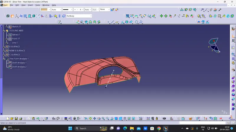
DRAFT ANALYSIS FOR THE CLASS A SURFACE USING THE MAIN TOOLING AXIS FROM THE FIRST METHOD:
Now, We will perform a Draft Analysis on the Class A Surface itself using the Main Tooling Axis created using the First Method:
Before starting with a Draft Analysis Operation, we will go to the 'Customize View Parameters' option under the 'View Toolbar'. Then we will enter the 'Customize View Mode' where we will go under the 'Mesh' option and select 'Material' and press 'OK'.
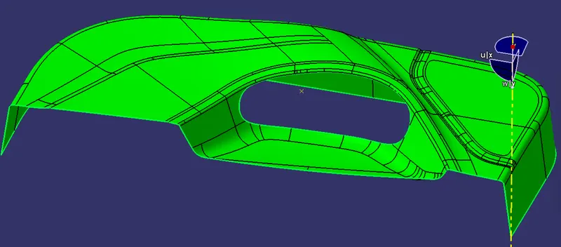
To start the Draft Analysis in the 'Generative Surface Design Workbench', we will go to 'Insert' and then look for the option called 'Analysis'. Once found, we will go under that and click on 'Feature Draft Analysis. This will open the 'Draft Analysis' Dialogue box. There, we will ensure that under 'Mode' we have selected 'Quick Analysis', under 'Display' we will select 'Show or Hide the Color Scale' and then select '3 Degrees' as the permissible draft angle. Then, under 'Direction' we will choose the icon with the symbol of the compass on it which stands for 'Use the Compass to define the new current draft direction'.
CLASS B SURFACE
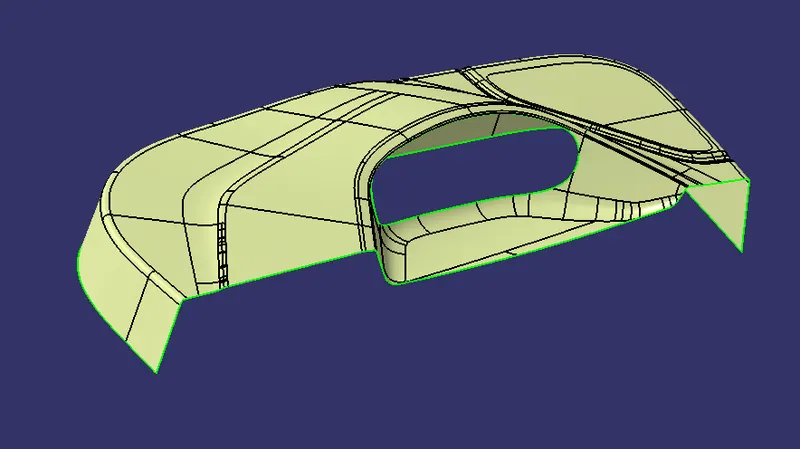
To create a class B surface class A surface is offset to 2.5mm and we have to work on the patches by using the multisection or sweep features if required 2.5mm is the thickness of the component
CLASS C SURFACE CREATION
Class C is nothing but connecting part of Class A & B. Unhide class A and takes the boundary of it and now boundary selects all corner of class A and uses sweep commands to create class c surface.
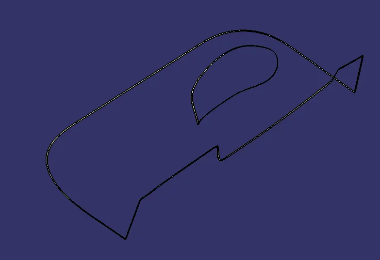
B) Inner Class C Surface:
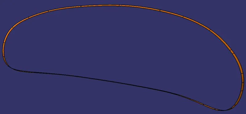
Now, we're going to Join the Class A Surface with both inner and outer Class C Surfaces as shown below:
hen We go to the part design workbench and use to closed surface tool to create a solid body.
hence, we created our final plastic component.
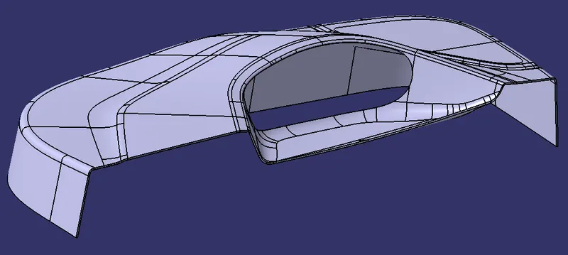
PROCEDURE TO ADD ENGINEERING FEATURES:
1. LOCATORS
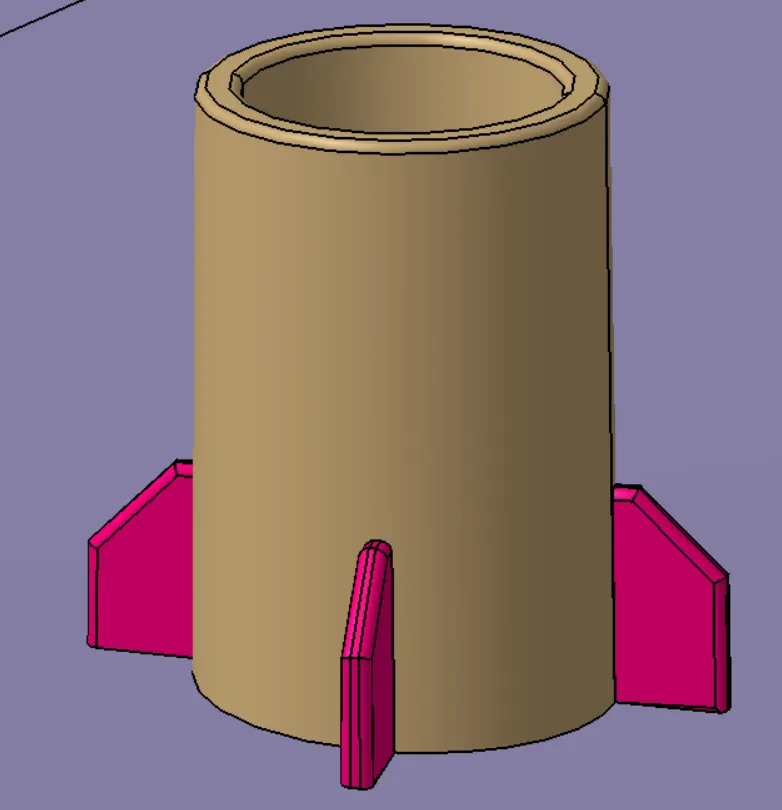
2. HEAT STAKES WITH GUSSETS
USE OF LOCATORS: Any workpiece has 12 degrees of freedom for movement in space that consists of 6 Axial and 6 Radial Degrees of Freedom. All 12 degrees of freedom must be restricted to ensure proper referencing of a workpiece. These 6 Axial Degrees of Freedom permit Straight-Line Movement in both directions along the 3-principle axis shown as X, Y & Z. The Radial Degrees of Freedom permit Rotational Movement, in both Clockwise & Counterclockwise radial directions around the same three axes.
We have two objectives when assembling the child component with the parent component:
1. Accurately position the part at the desired coordinates.
2. Restrict all degrees of freedom except the one direction in which it'll fix so that the part cannot move.
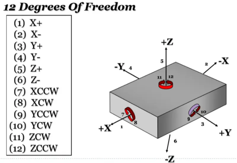
PROCEDURE TO CREATE THE LOCATORS:
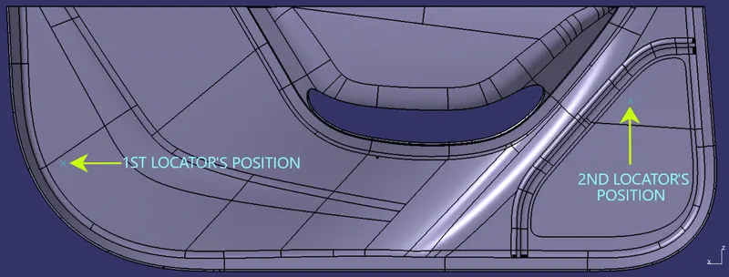
We'll create the points at which we are supposed to create the locator using the reference image provided with the challenge as shown below:
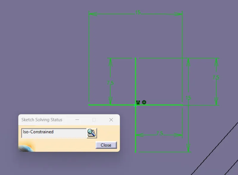
We'll create the necessary plane so that we can create a positioned sketch with a projection point for the locator as shown below:
SKETCH FOR THE LOCATOR:
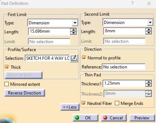
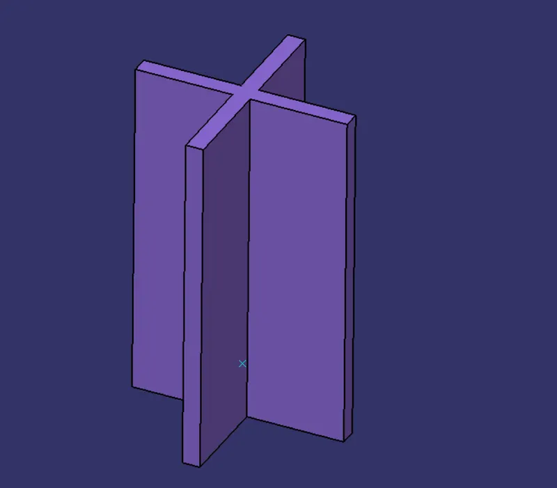
Then, we'll go to the Part Workbench and use the PAD Command to create a Thickened Body with Neutral Fiber as shown below:
1. PAD DEFINITION:
2. DRAFT DEFINITION:
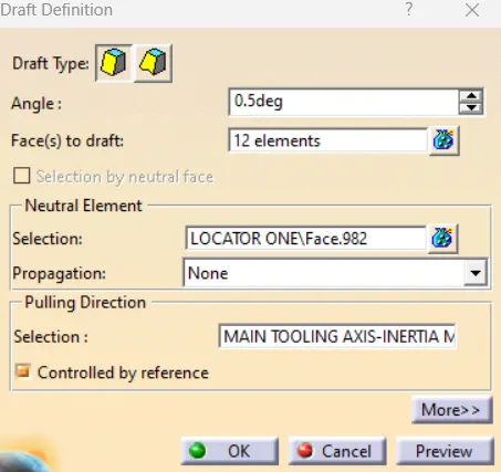
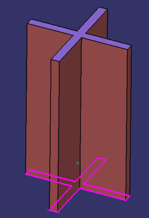
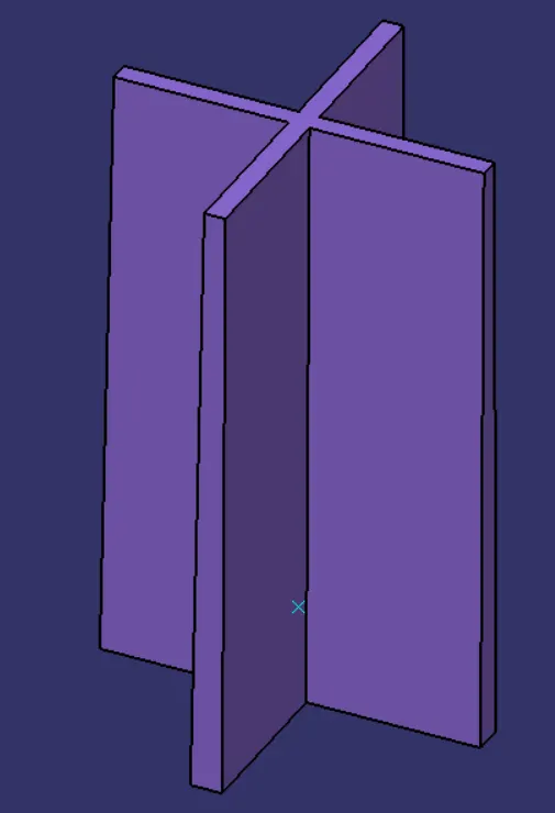
After providing the draft we'll check the wall thickness at the top section as it should be greater than 0.75mm according to the design rules.
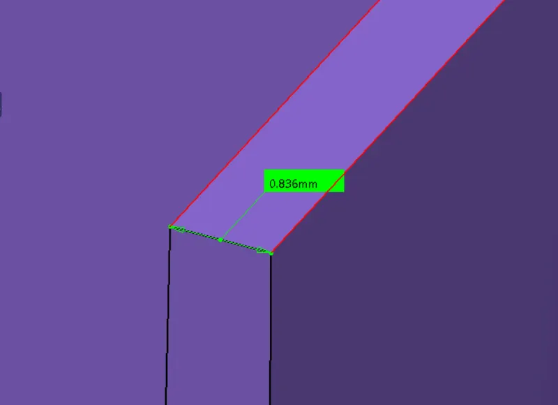
3. CHAMFER DEFINITION:
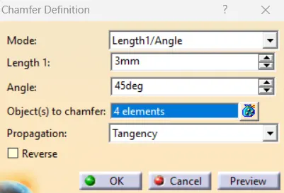
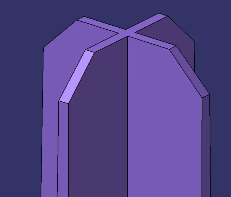
4. EDGE FILLET DEFINITION:
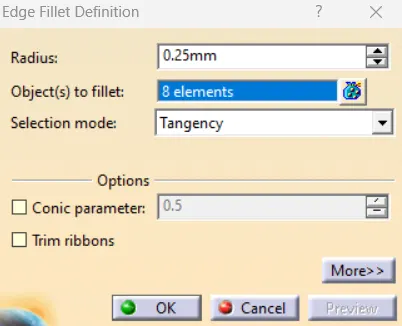
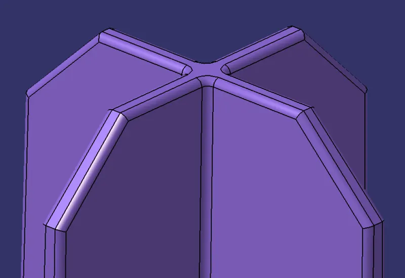
COMPLETE VIEW OF THE LOCATOR:
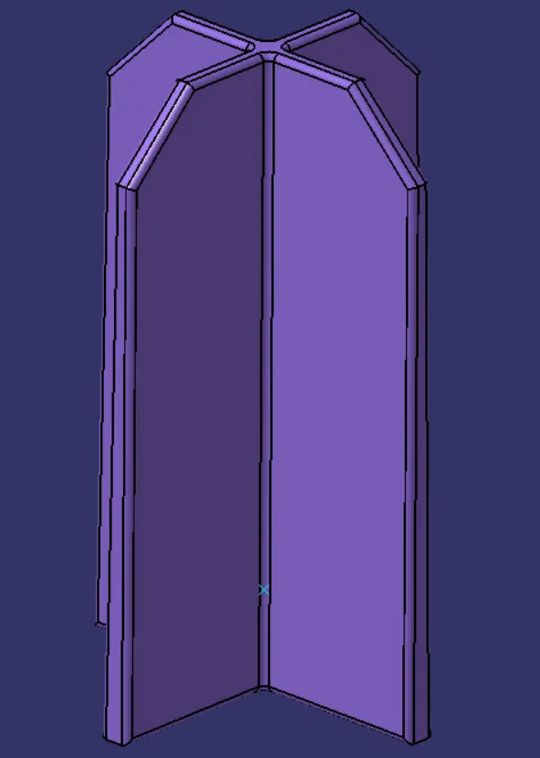
1ST LOCATOR:
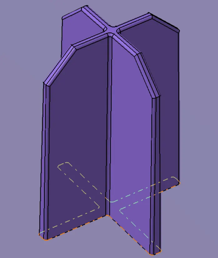
2ND LOCATOR:
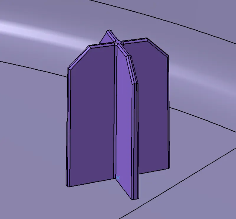
Similarly, we'll build the second locator and assemble them both with our plastic component using via Boolean Operation of Union Trim as shown below:
PROCEDURE TO CREATE THE HEAT STAKES:
We'll create Heat Stakes at points as shown below: These points were provided with the challenge for the Heat Stakes.
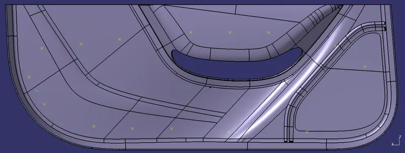
To create a Heat Stake, we'll begin with a Positioned Sketch as shown below:
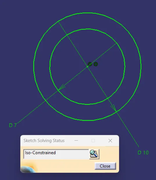
According to the Design Rules, the Wall thickness of the Heat Stake should be within 60% of the Thickness of the Plastic Component and since the thickness of our Plastic Component is 2.5mm hence 60% of it is 1.5mm.
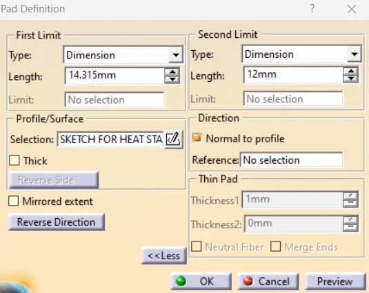
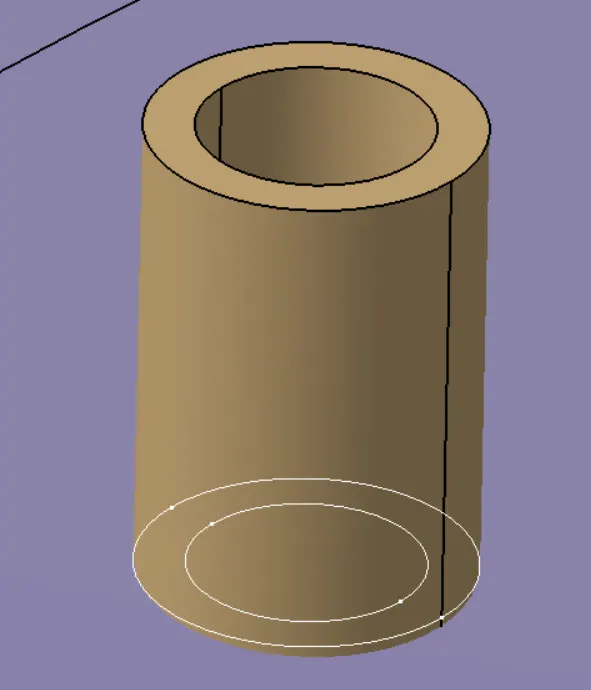
1. PAD DEFINITION:
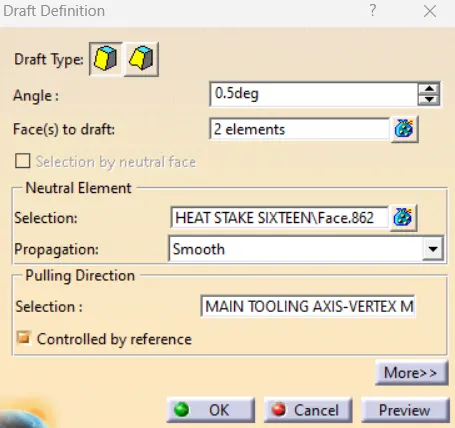
2. DRAFT DEFINITION:
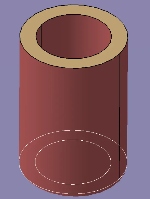
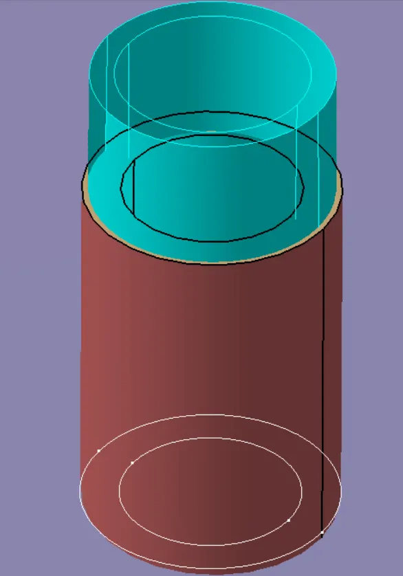
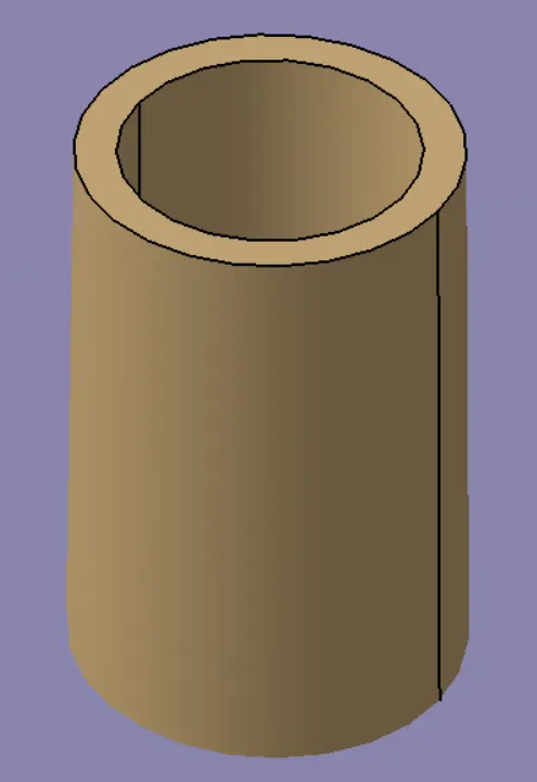
3. EDGE FILLET DEFINITION:
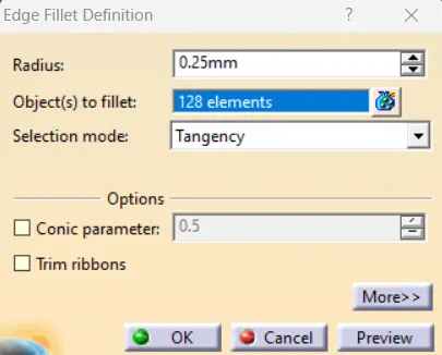
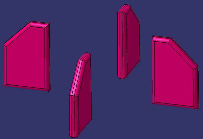
After creating all the Heat Stakes at the required positions, we'll provide an Edge-Fillet definition of 0.25mm following the Design Rules.
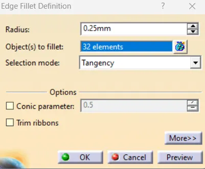
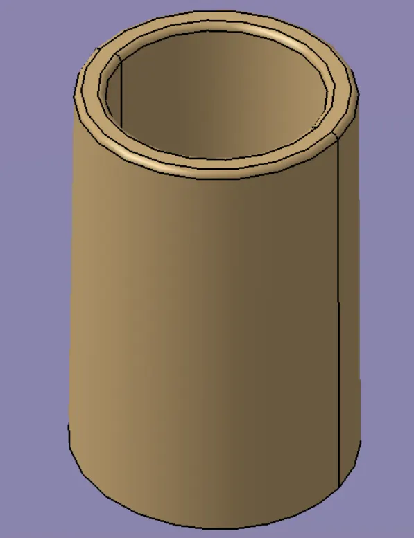
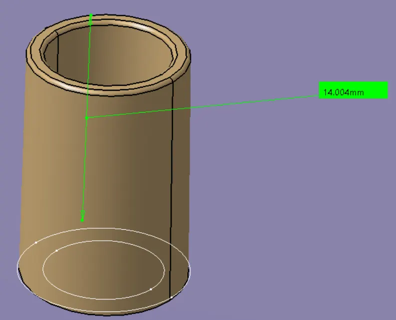
We'll limit the height of the Heat Stake to 14mm from the surface on which it is created as shown below:
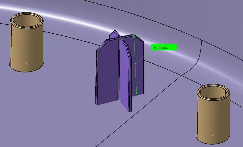
The height of the Locators will be around 20mm so that locators can come in contact with the parent component first and accordingly the heat stakes positions will get located on their own.
PROCEDURE TO CREATE GUSSETS FOR THE HEAT STAKES:
Gussets are Support Features that Reinforce Areas such as Walls or Bosses to the floor. Just as bridge beams and columns are supported at their vertex with gussets to add critical strength to the structure, the same concept applies to plastic injection moulding.
The difference between Ribs and Gussets is that ribs are usually thin wall supports added internally around walls to achieve better geometry and support. Gussets, on the other hand, are thicker wall supports to add strength and reinforcement to existing plastic features.
Recommended Thickness of a Gusset at the Wall is 50% of the Wall Thickness. Typically, the gusset height is less than four times the wall thickness, preferably two times the wall thickness.
REQUIRED SKETCH FOR GUSSETS:
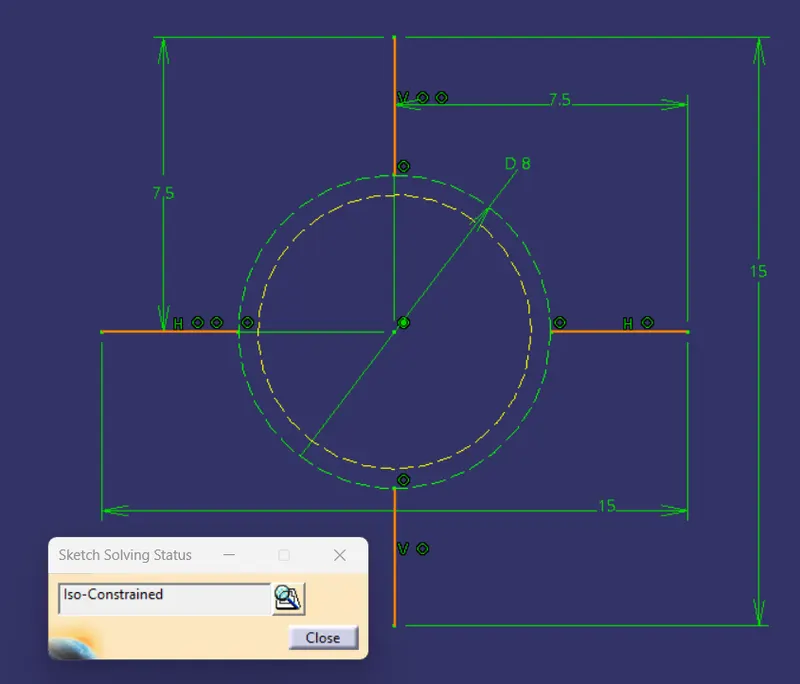
1. PAD DEFINITION:
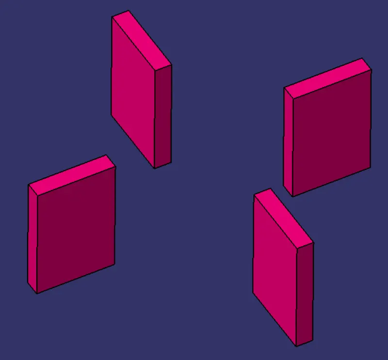
2. DRAFT DEFINITION:
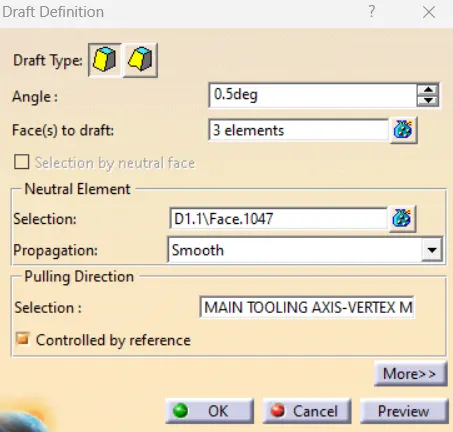
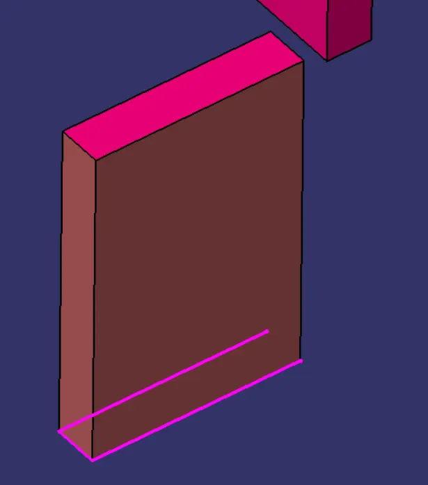
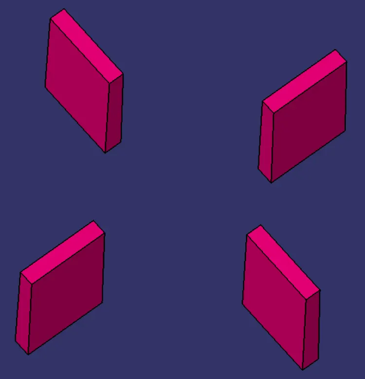
We'll provide a draft of 0.5 degrees on all the required faces as shown below:
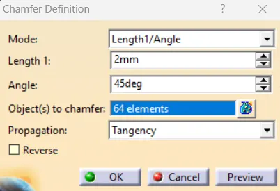
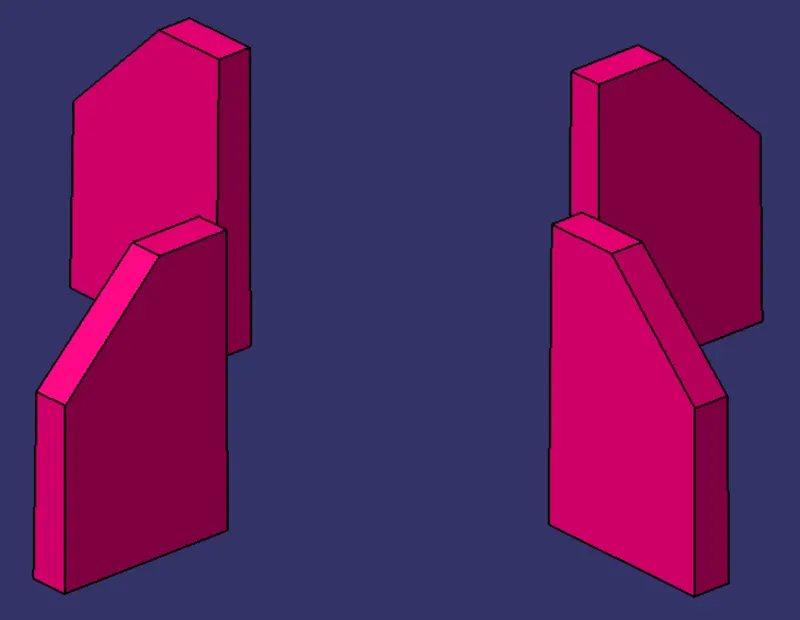
3. CHAMFER DEFINITION:
4. EDGE FILLET DEFINITION:
HEAT STAKE WITH GUSSETS:
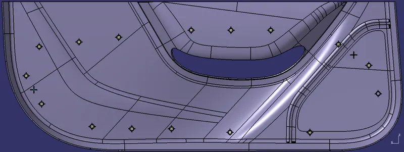
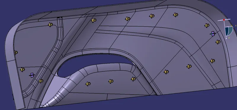
OUR FINAL PLASTIC COMPONENT WITH ALL THE NECESSARY ENGINEERING FEATURES:
DRAFT ANALYSIS ON THE ENGINEERING FEATURES:
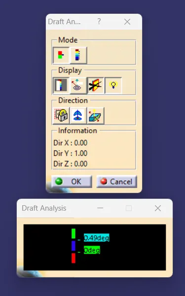
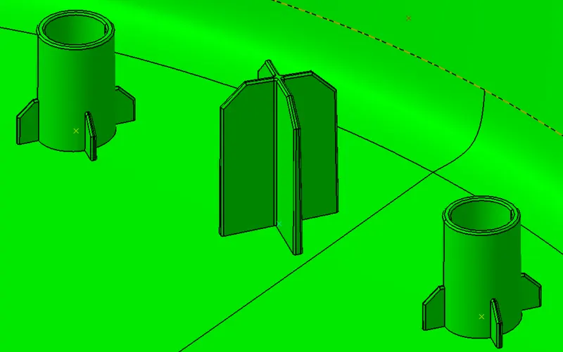
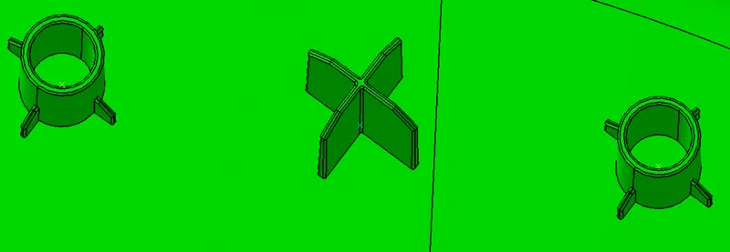
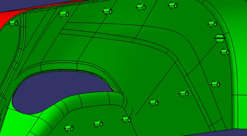
From the above images, we can see that the required draft angle is met and these features will clear themselves along the Main Tooling Axis for an angle of 0.5 degrees.
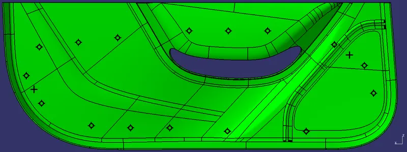
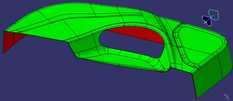
3D VIEWS OF THE FINAL PART WITH PROPER COLOR CODE OF THE DRAFT ANGLE IN VARIOUS ORIENTATIONS:
1. FRONT VIEW:
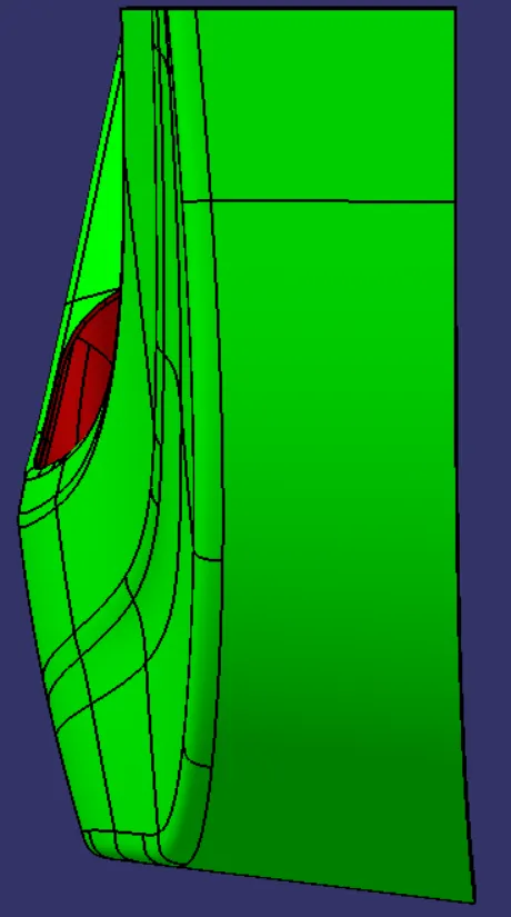
2. TOP VIEW:
3. ISOMETRIC VIEW:
Conclusion:
- Created the Door Trim Plastic component through the given Class-A surface, the tooling axis for the given Class-A Surface, met the draft angle requirements, and performed the draft analysis on the model at the end.
- And also created the Heat Stakes and the locators considering the design rules