Week 8 - Challenge 1 - Base Bracket Design
Create the Base Bracket Plastic component through the given Class-A surface. To begin with, the tooling axis for the given Class-A Surface should be created meeting the requirements of the draft angle and at the end perform the Draft analysis on t 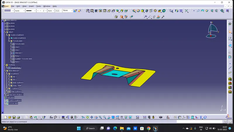
given model class a surface
PROCEDURE:
step 1: Tooling axis creation
A surface to create the tooling axis, for the component thw above given base bracket z-axis is the best suitable axis to work on it
step 2:line
lines are drawn to the side faces of the intresected curve then bisecting the line is created between these two lines.
in thus way to create the tooling direction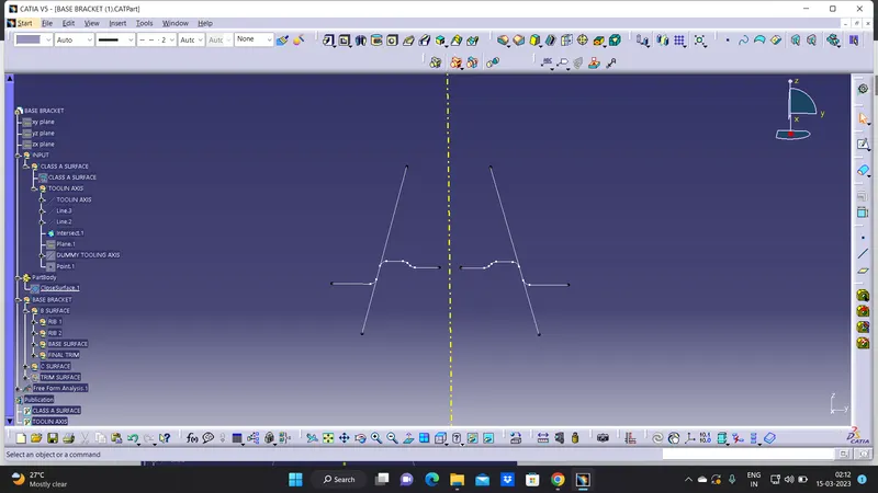
draft analysis:
Draft analysis is performed based on color ranges idetifying zones on the analyed element where the deviation from the draft analysis direction at any point ,corresponds to specified values . minimum draft angle is considered as 3 degree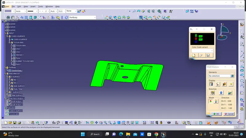
B-Surface :
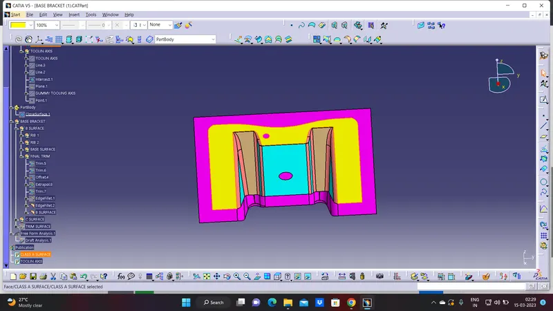
class b surface is extracted from the A-Surface and it is offseted at 2.5mm in downward dirction
step to offset firts we need to RIB 1& RIB 2 offsect then base surface trim all the tree of them we get B-SURFACE
C-SURFACE :
C-SURFACE connects the tha CLASS A-SURFACE AND B-SURFACE .IT IS CREATED USING SWEEP COMMAND BOUNDARY. BOUNDARY OF THE CLASS A-SURFACE IT SWEPT ALONG THE TOOLING DIRECTION
TRIM SURFACE :
TRIM THE SURFACE A &C ARE JOINED TOGETHER THEN IT IS TRIMMED ALONG THE B-SURFACE
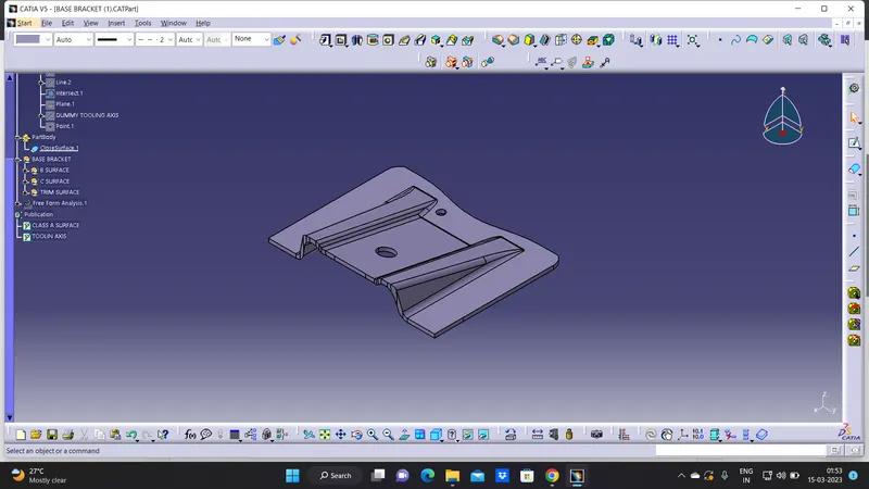
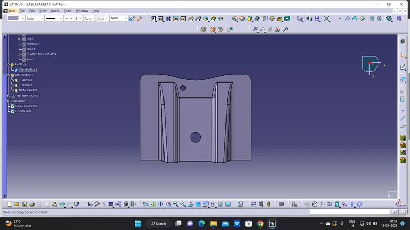
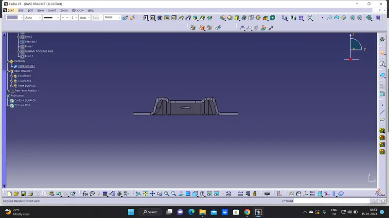
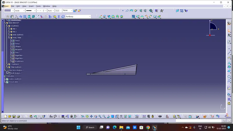
THE BASE BRACKET PLASTIC COMPONENT HAS BEEN DESIGNED USING THE GIVEN CLASS A-SURFACE