Week 10 - Challenge 2- Attachment Feature Creation (Dog House)
AIM:- Create the Dog House for the Door Trim considering the design rules mentioned in the video. Consider the thickness of the part to be 2.5 mm.
Introduction:-
Dog house:-
Dog house is an engineering feature used in plastic design. Dog houses are used as a support feature. Sometimes other engineering features like snaps, locators, and screw bosses are mounted on them to increase their strength.
Dog houses are subjected to draft analysis to prevent breakage of the component during ejection from the mold cavity. Dog house and other engineering components are built on the B-surface.
Objective:-
- Create a Tooling axis for the given CLASS -A surface.
- Create the CLASS B and C surfaces of door trim using the given CLASS-A surface.
- Create a final surface model and convert it into a solid body using the close surface command in the part design workbench.
- Create a side core axis for the dog house
- Create a Dog house on the B surface by considering the design rules.
- Perform draft analysis for both Class-A surface and Final part body.
Design Procedure:-
We were given input class-A surface.
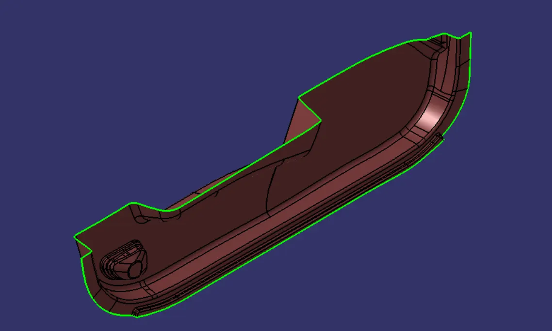
Now check for surface quality is there any gap in Class A by using the Join or Boundry command. If the quality of the surface is good then create the tooling axis for the part.
Procedure for Tooling axis creation
- Check the best possible tooling direction by manually adjusting the compass.
- By analyzing it is found that the y-axis as tooling direction would clear most of the faces without any difficulties.
- Create a point on the class A surface with a 0 value so it will by default take the center point of Class A.
- Then create a dummy axis creating a line on the point and direction along the y-axis.
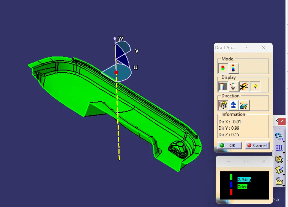
- Perform draft analysis to find whether the given axis clears the draft analysis. If not create a new tooling axis.
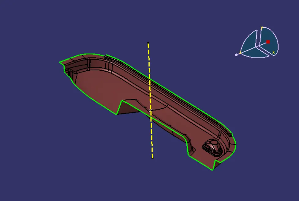
Draft analysis of CLASS-A surface-
CLASS-B surface creation-
Class B surface is the surface on which all the engineering elements are created or placed. It is the back side of the component which is visible to the user.
- Create offset surface of class-A about 2.5mm inward direction because Class B is at the back side of the component.
- Check for discontinuity and rework on the offset surface using extract, multi-extract, multi-section surfaces, and blend, etc.
- Create individual geometrical sets for every patch it will make our work easy and clean.
- Join the surfaces and ensure the final CLASS-B surface created has no gaps.
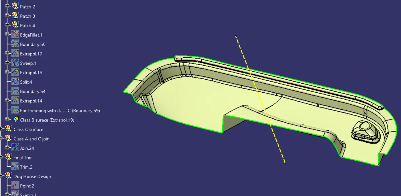
CLASS-C surface creation-
- Create a boundary of class-A surface using the boundary command or multiple-extract command.
- Then create a sweep using the created boundary with the draft direction option and choose the tooling direction.
- Extrapolate both the class-C surfaces and then trim them together to form a complete class-A surface.
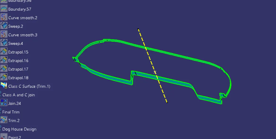
Creating the Final trimmed surface-
- For creating the final door trim surface, join the CLASS-A and CLASS-C surfaces together.
- Then Extrapolate the B surface a little bit outward direction to make sure that there would not be any gap when trimming with the joined surface.
- Then trim the extrapolated CLASS-B surface with the CLASS-A and CLASS-C join.
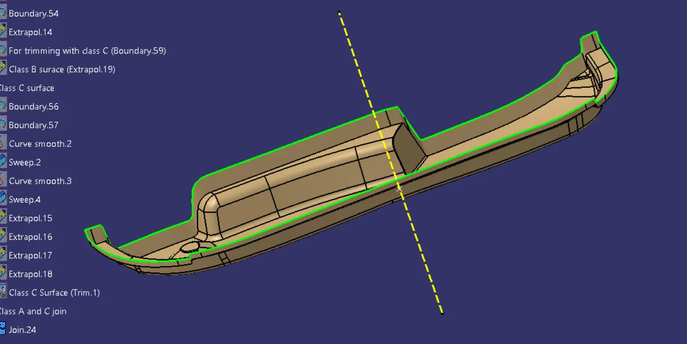
Closed Surface-
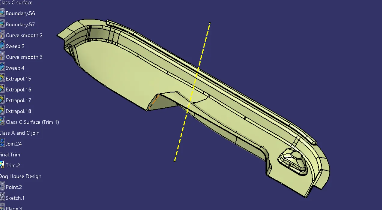
Make a solid part body using the close surface command in the part design workbench-
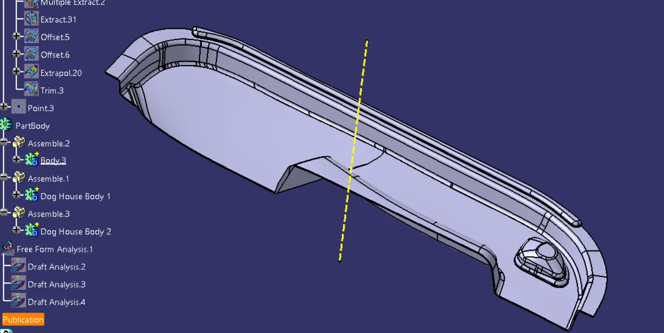
DOG HOUSE Creation
- Dog houses are designed to avoid SINK MARK created on the CLASS-A surface by screw bosses and to solve the length issues when giving screw bosses which need to be assembled to other components.
- It is also useful when perpendicular screw bosses are required on the part to the tooling direction.
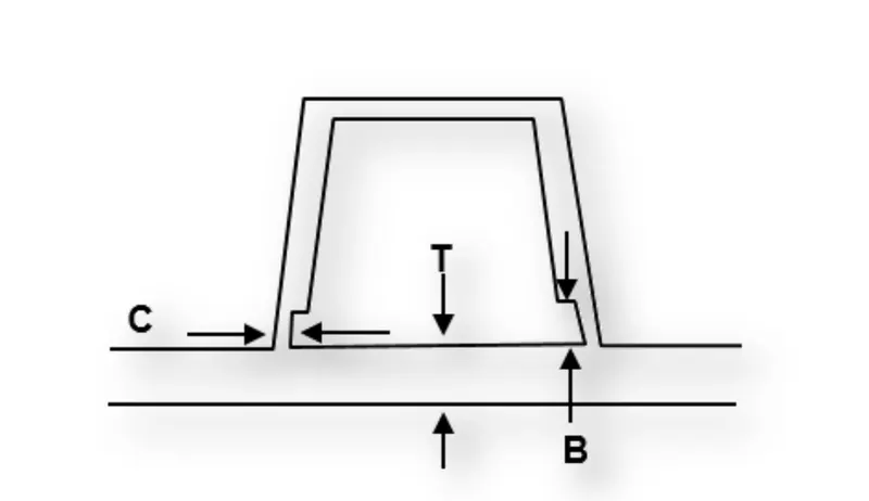
- C thickness should be 40% of the main wall thickness T
"C" is where the doghouse contacts the backside of the surface
Doghouse wall thickness at the intersection of the part wall ( C ) should be 40% or less than the main wall stock ( T ).
The height of ( B ) should be between 3.0 – 6.0 mm
- The minimum width of the dog house is 12 mm.
- The height of B should be 3-6 mm
- The minimum draft for the dog house degree is 1.5 degrees per side to die draw.
Procedure for creating the DOG HOUSE- - Create a point where the dog house is to be positioned.
- Then create a positioned sketch of a dog house.
- Also, a side core axis for the dog house using a point and direction line should be created so that it can clear the inner faces of the dog house.
- Create dog house walls either by creating a sweep or by extruding command.
- Give proper draft angles and fillets by considering the design rules
- Use boolean operation Union trim or assemble the dog house part body with door lower trim.
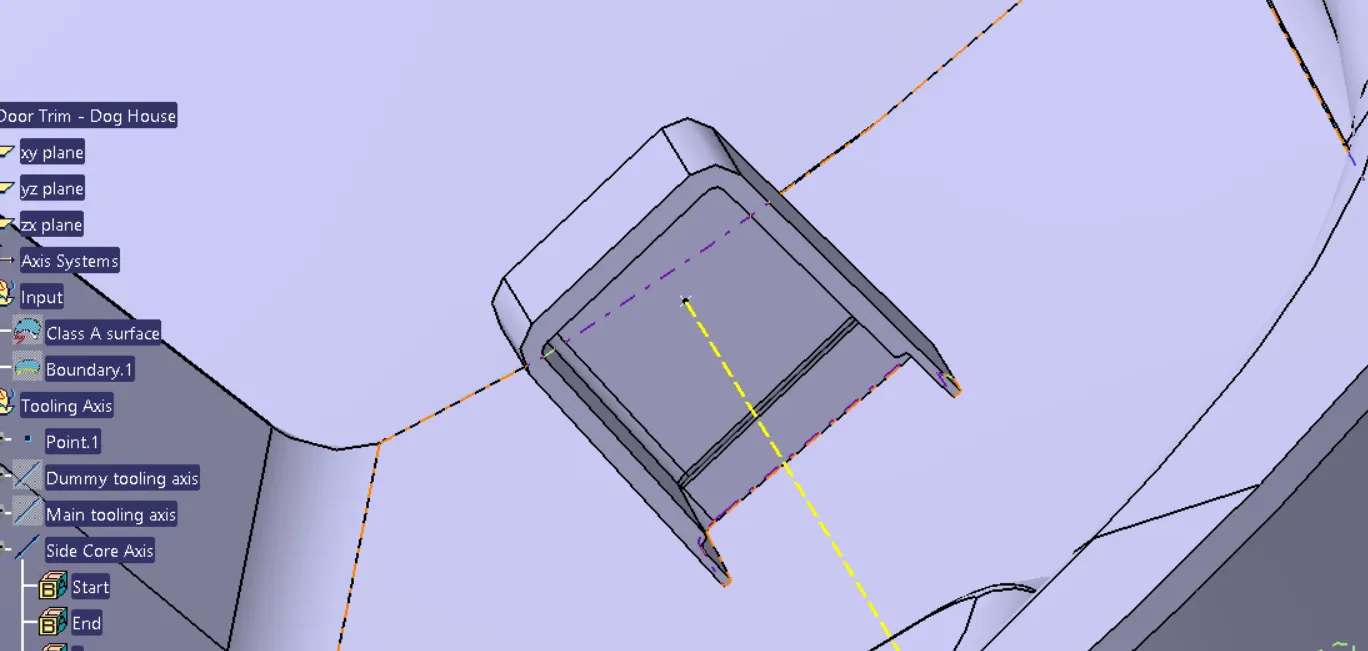
- Then translate (point to Point) the copied dog house in order to create a 2nd dog hose as shown-
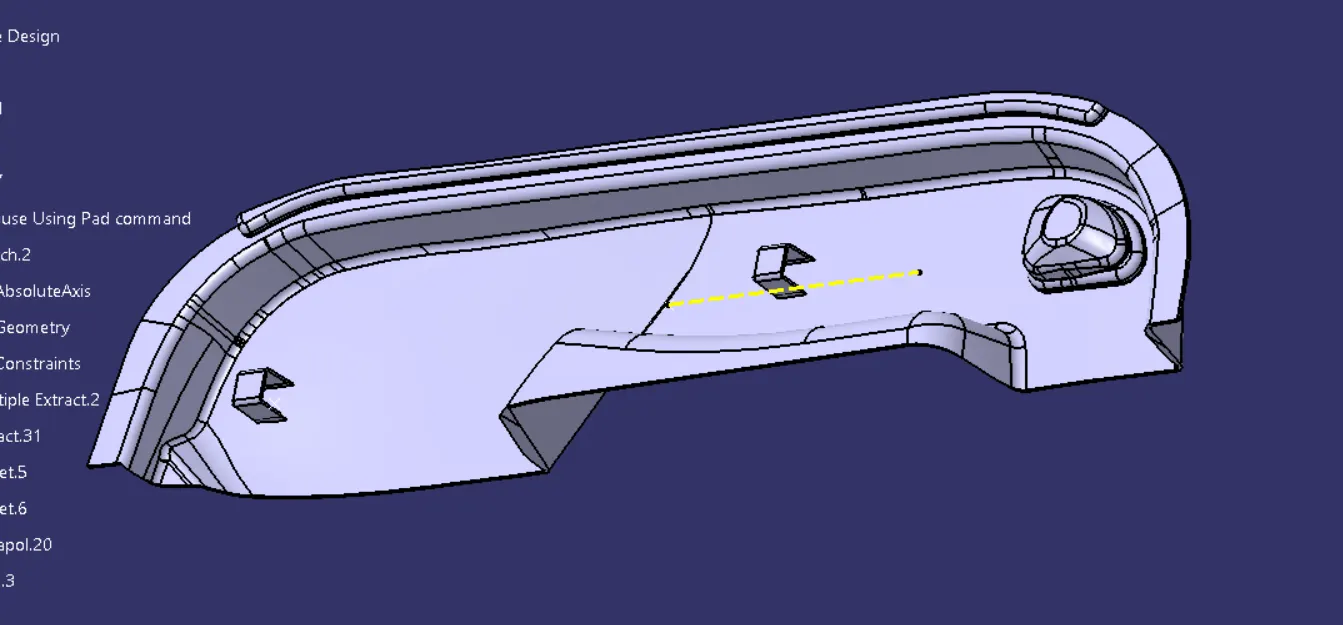
DRAFT ANALYSIS-
Draft analysis is done after determining the tooling axis, draft analysis is used to check whether the minimum draft (3 degrees) is maintained or not.
- The procedure for performing the draft analysis is as follows
- Change the view mode of the component to be in customized parameter mode and then select the shading mode as materials.
- Then open the featured draft analysis tool from the insert menu.
- Then click on the use the compass to define the current drafting direction and then drag and align the compass on the Tooling axis.
- Then lock the draft direction and perform draft analysis by clicking on the component.
Color Range representation:-
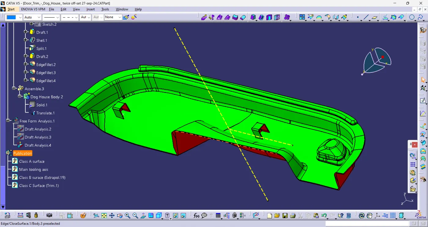
GREEN color - Positive Draft
BLUE color – Zero draft or draft value in between the given range.
RED color – Negative Draft
Dog House draft analysis using the side core axis-
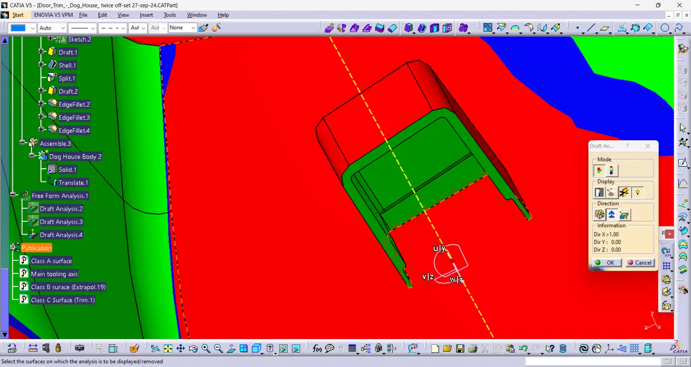
Final part draft analysis using the main tooling axis-
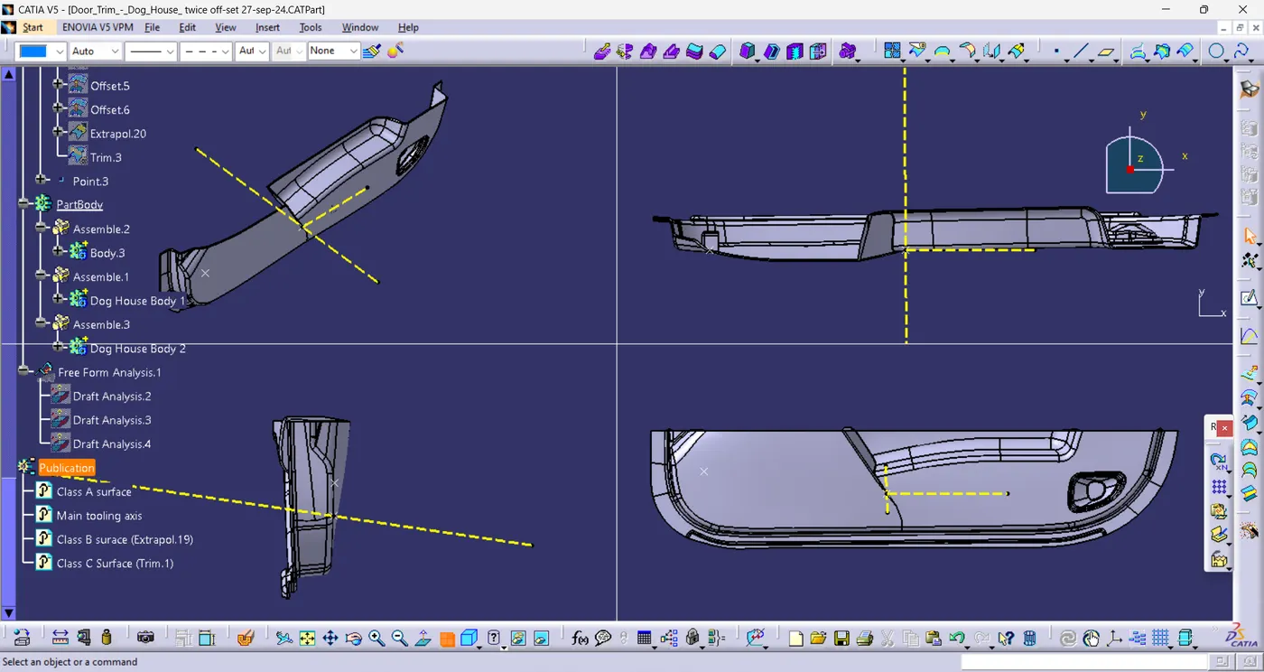
3D Part model in various orientations-
Conclusion-
Created the component following all the instruction given below-
- Sketches
- Use Positioned sketch
- Sketches should be Iso-Constrained
- Tree Structure
- Ensure Proper Tree Structure
- Geometrical sets should have a proper name based on the sketches present inside of it
- All the sketches should be created under the Geometrical set
- Report
- A detailed report should be done explaining the draft analysis and the tooling axis creation.
- An explanation should be given on the way of creating the tooling axis, particularly the Bisecting method
- Reference
- Refer to the below-given image to understand the positions of the Dog House