Week 10 - Challenge 2- Attachment Feature Creation (Dog House)
AIM : To Create the Dog House for the Door Trim considering the design rules mentioned and Consider the thickness of the part to be 2.5 mm.
- A detailed report should be done explaining the draft analysis and the tooling axis creation.
1) Creation of Tooling Axis
For creation of Tooling Axis , First we will view the Class A Surface from different directions to find out the optimal direction along which we can create our Tooling Axis
In X Direction :
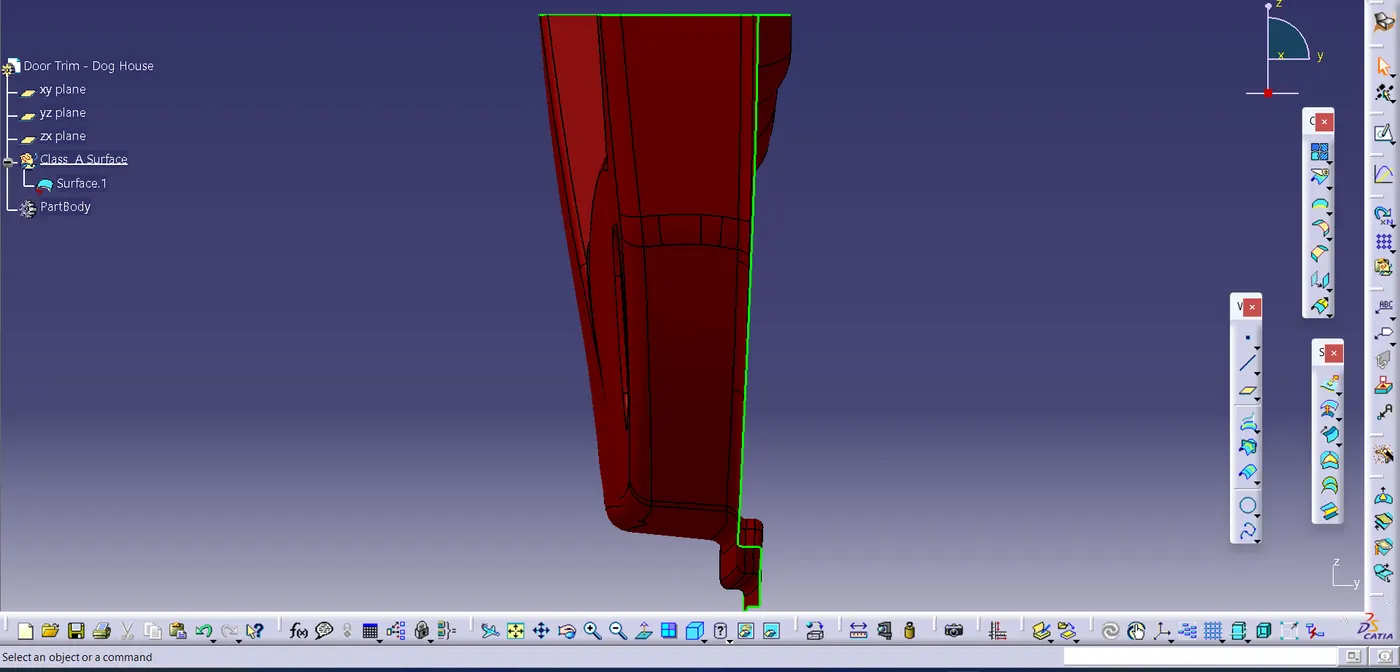
From the above image, we can see that not much surface area is exposed along this direction and hence this cannot be the direction along which we can create our Main Tooling Axis:
In Y Direction :
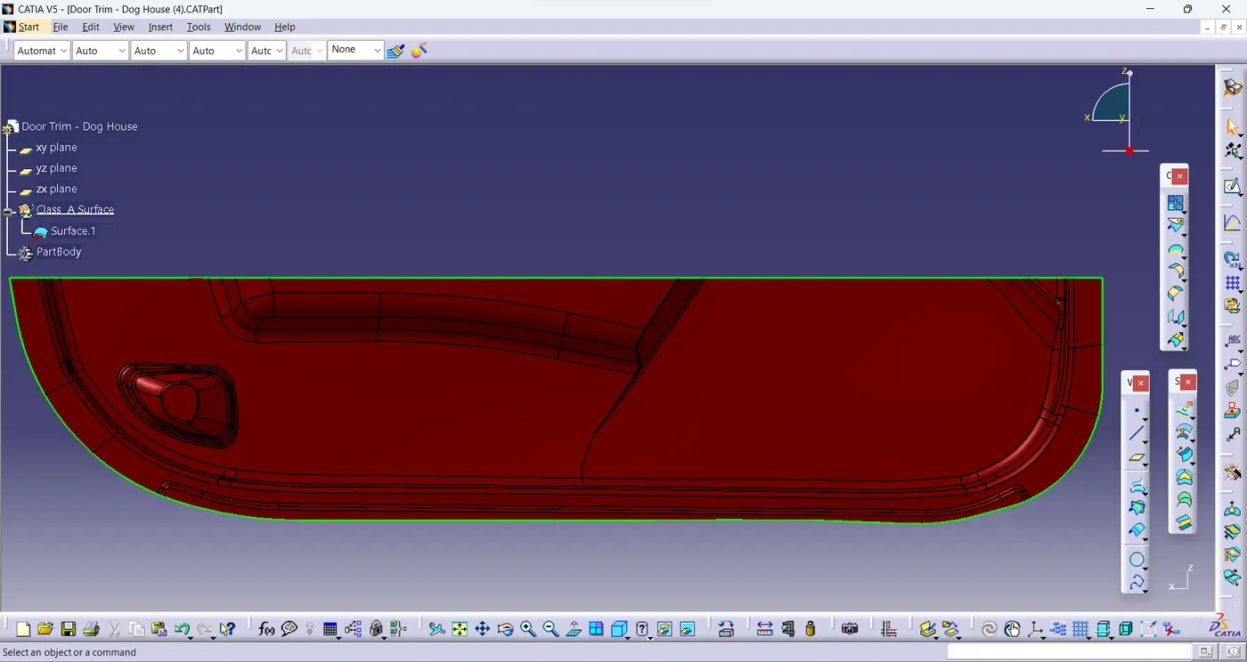
From the above image, we can see that the maximum surface area is exposed along this direction and hence we have to construct our Main Tooling Axis along this direction.
In Z Direction :
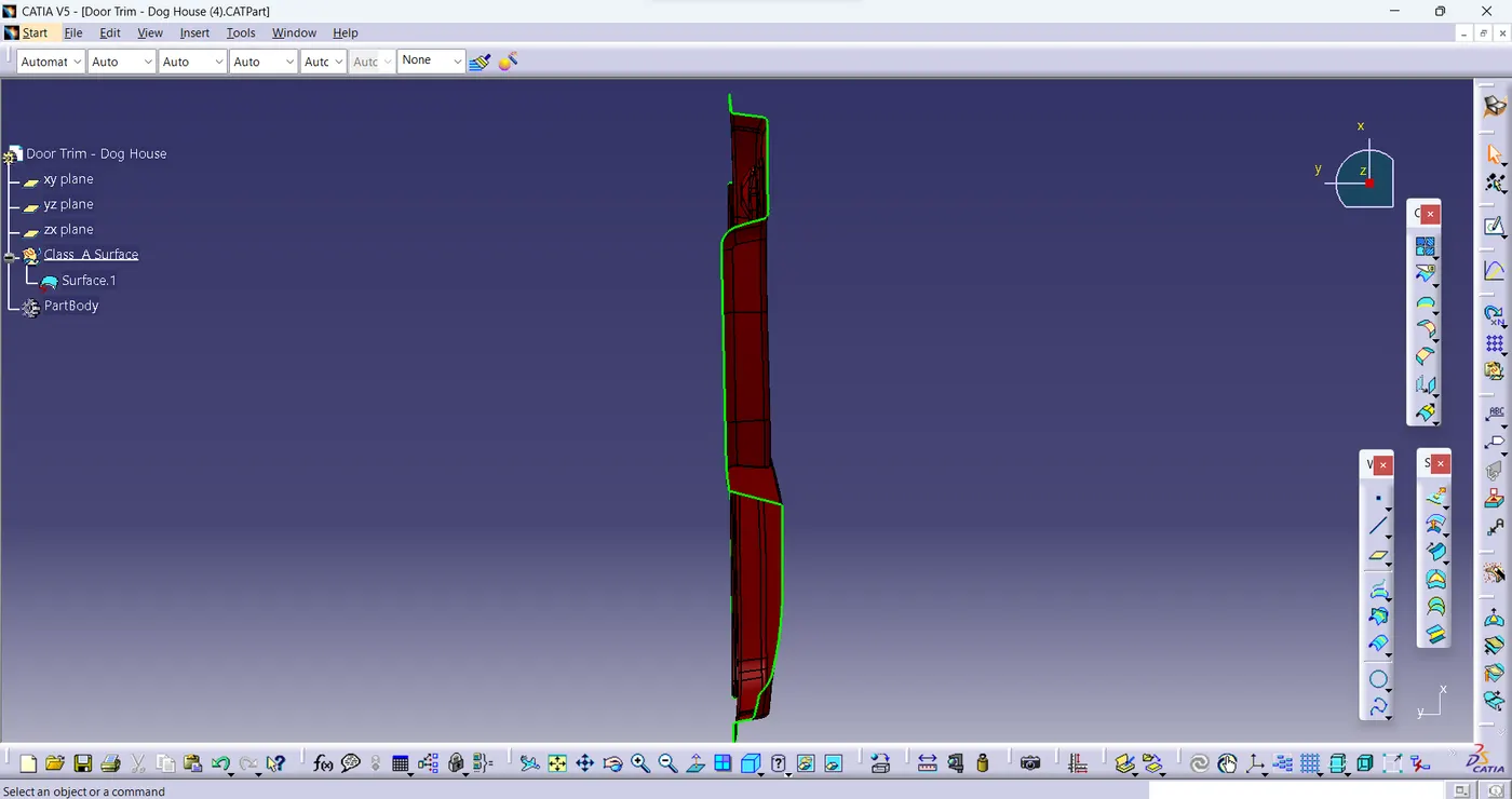
From the above image, we can see that not much area is exposed along this direction as well and hence this as well cannot be the direction along which we can create our Main Tooling Axis.
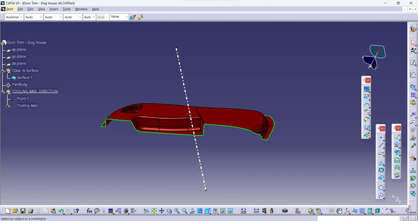
Since the direction is the most important factor while creating the Main Tooling Axis, and once the direction is known we'll just pick any vertex at the extremity of the Class A Surface and create a line using that point along Y direction or Use the " Inertia Method "to find out the Center of Gravity and use that point to create a line along the required direction for the Main Tooling Axis. We have to perform a draft analysis on the Class A Surface to crosscheck if feasible to be the Main Tooling Axis or not.
Inertia Method
This method may not work for every component but it was considered to be used for this component.
- click on the " Measure Inertia " icon from the ''Measure Toolbar'' as shown below
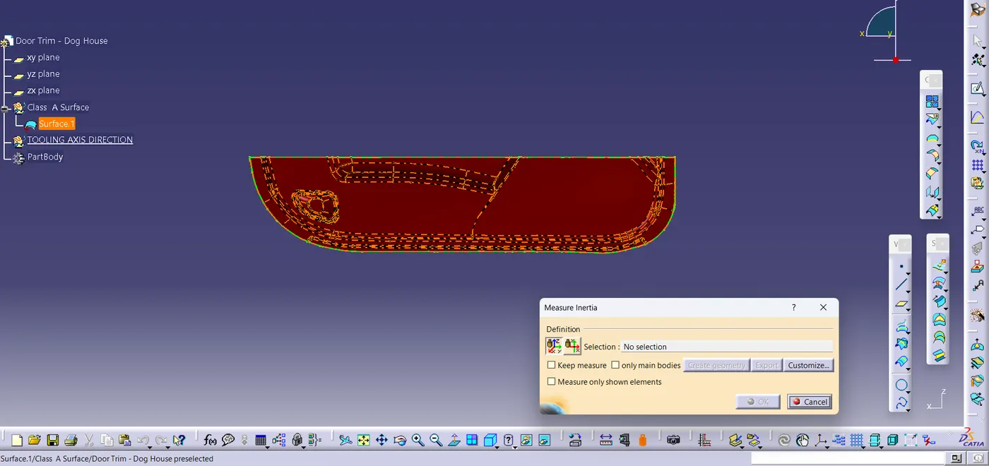
2.select our Class A Surface in the 'Measure Inertia' dialogue box as shown below:
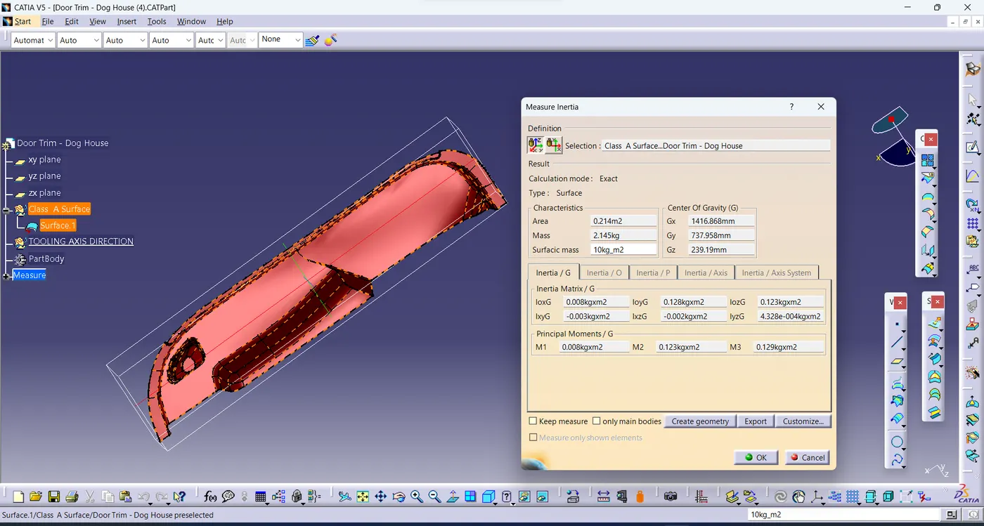
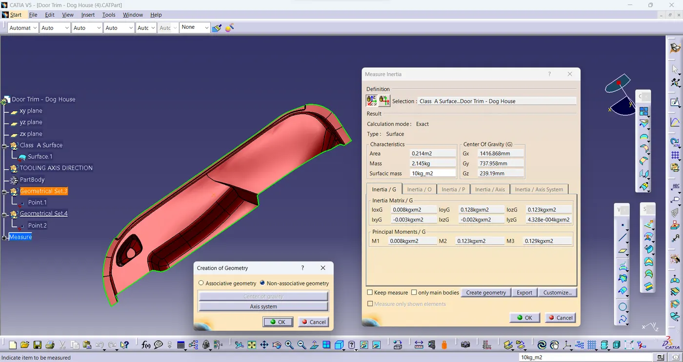
click on the 'Create Geometry' option in Measure Inertia Window that'll open up the 'Creation of Geometry' window.
There choose 'Non-Associative Geometry' and then click on 'Center of Gravity' to create the required C.G point as shown below
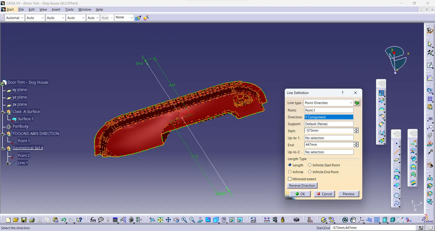
3.Now, create a line along the Y-Axis using the 'Line-Definition' command while choosing our Line-Type as 'Point-Direction' we'll create a line along the Y-Axis as shown below:
Creation of Side Core Tooling Axis :
- Create a Extract on Dog House part and create a point on that extract surface as shown
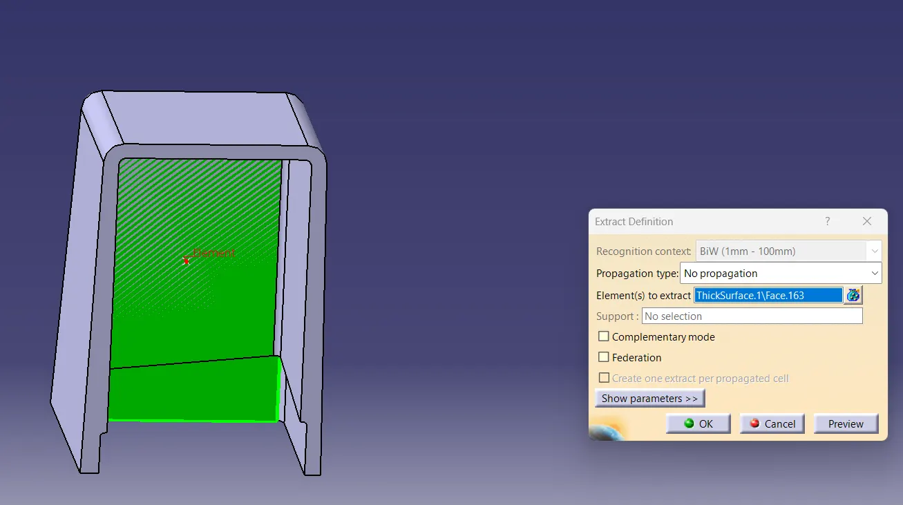
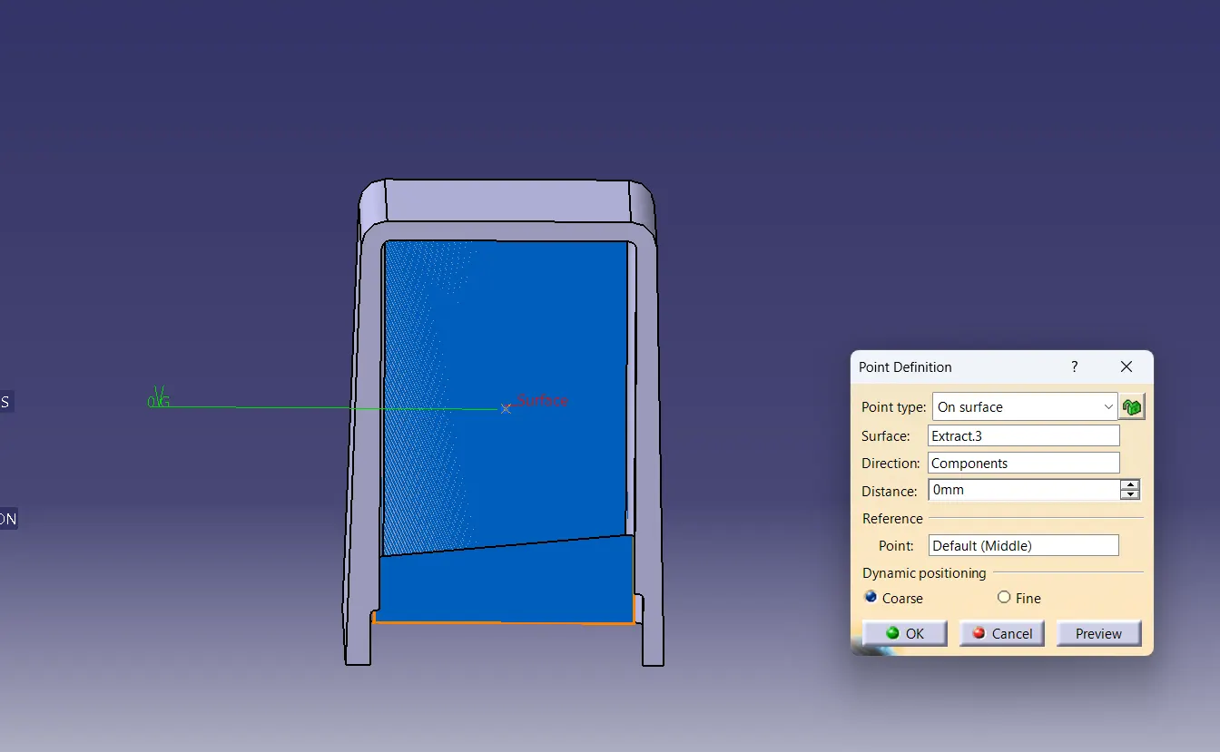
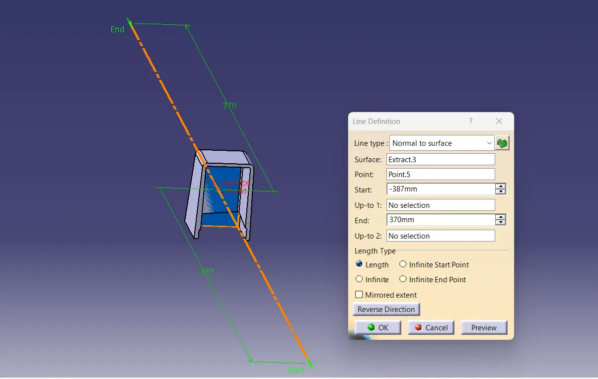
2) Draft Analysis Report
Before starting with a Draft Analysis Operation, we will go to the ''Customize View Parameters'' option under the 'View Toolbar'. Then we will enter the 'Customize View Mode' where we will go under the 'Mesh' option and select 'Material' and press 'OK'.
i)Go to Insert------>Analysis-------->Feature Draft Analysis
ii) Drag the Compass and palce it over the Tooling Axis then click on the component
iii) Now Activate the compass by selecting compass icon under Direction section in Draft Analysis dialogue box . then remove the compass lying on the tooling axis and again place it over the Tooling Axis and
again click on the component .
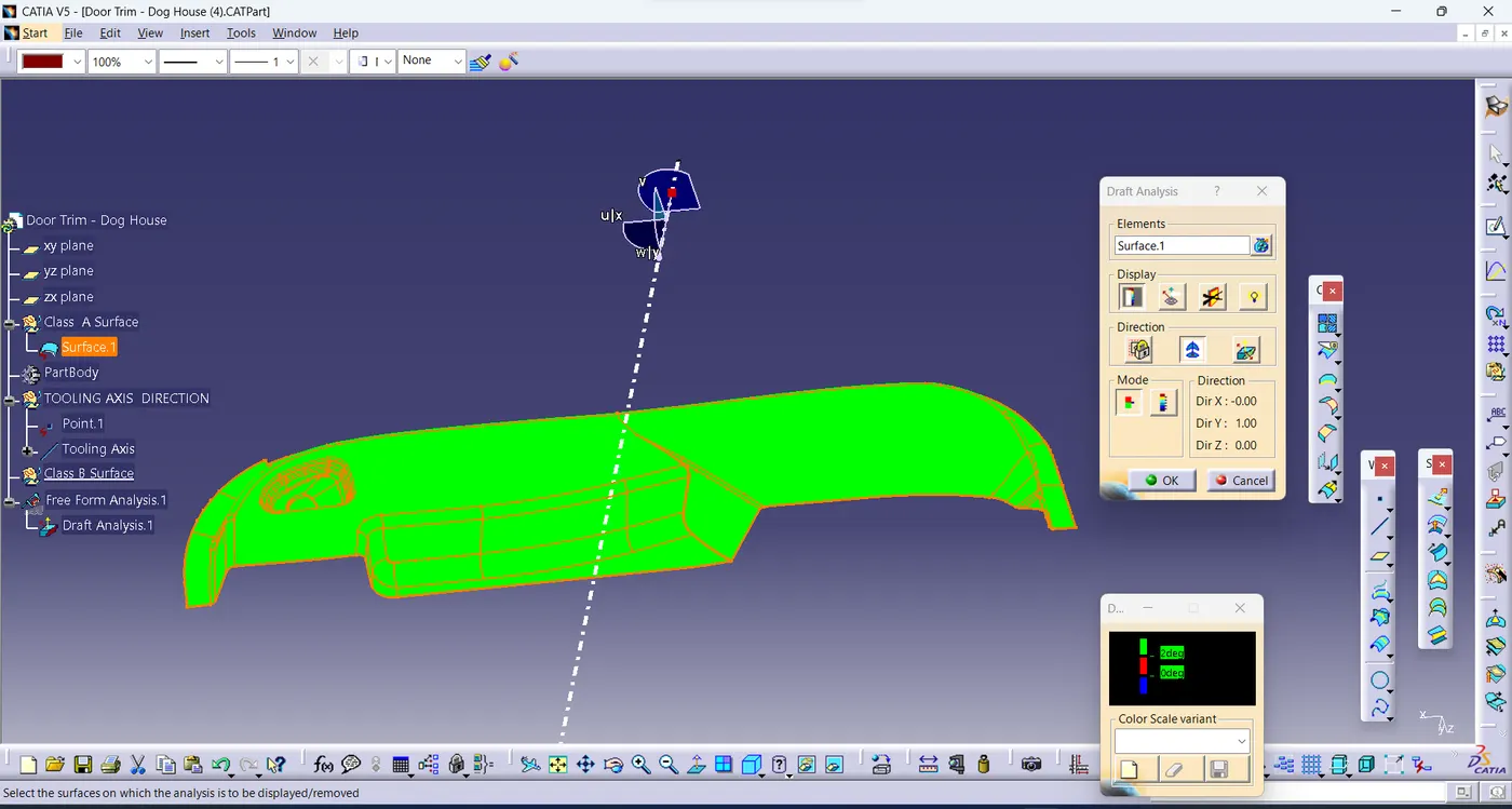
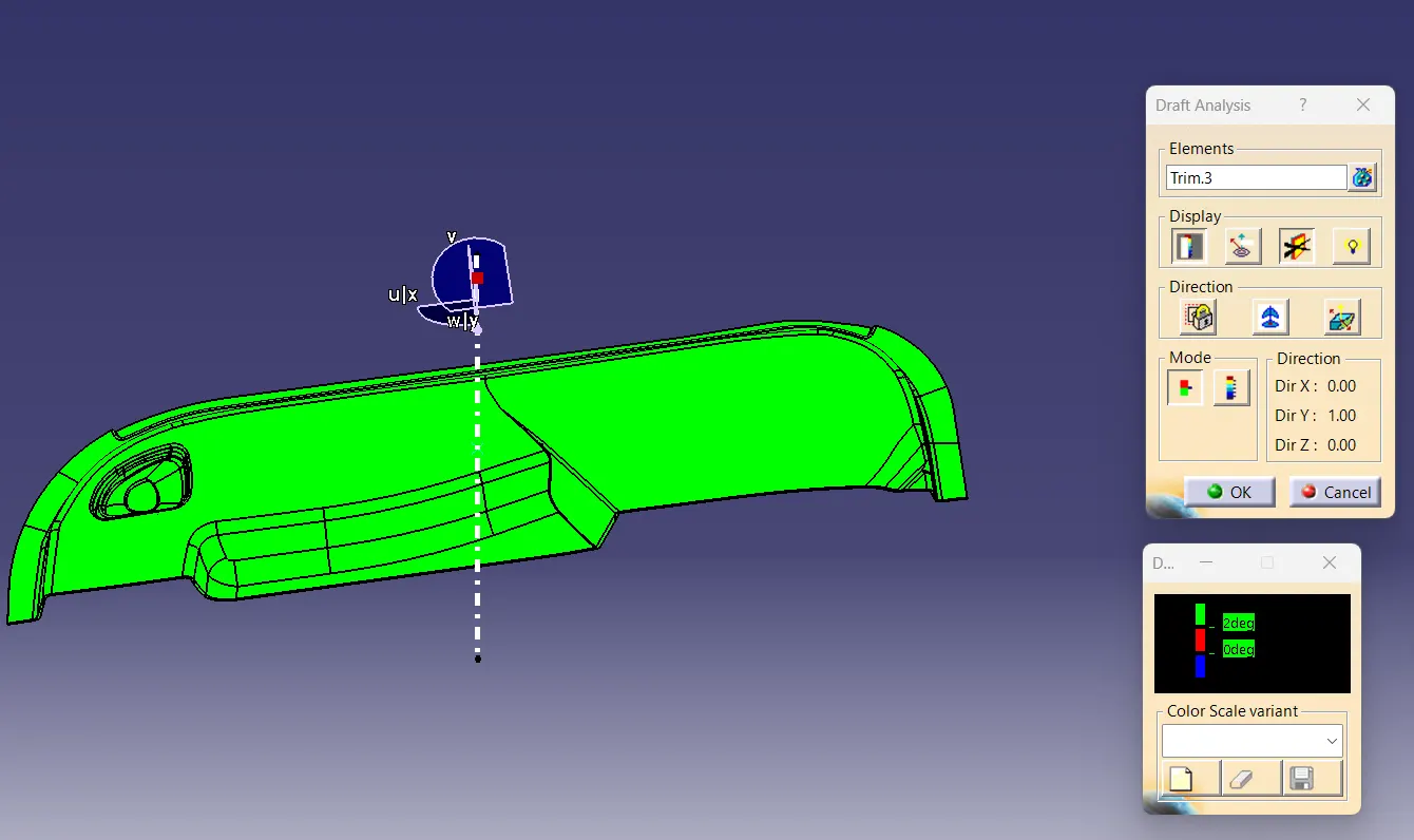
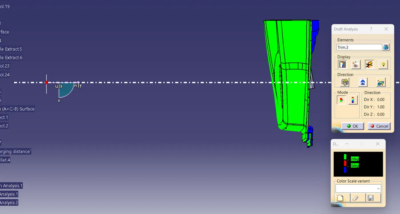
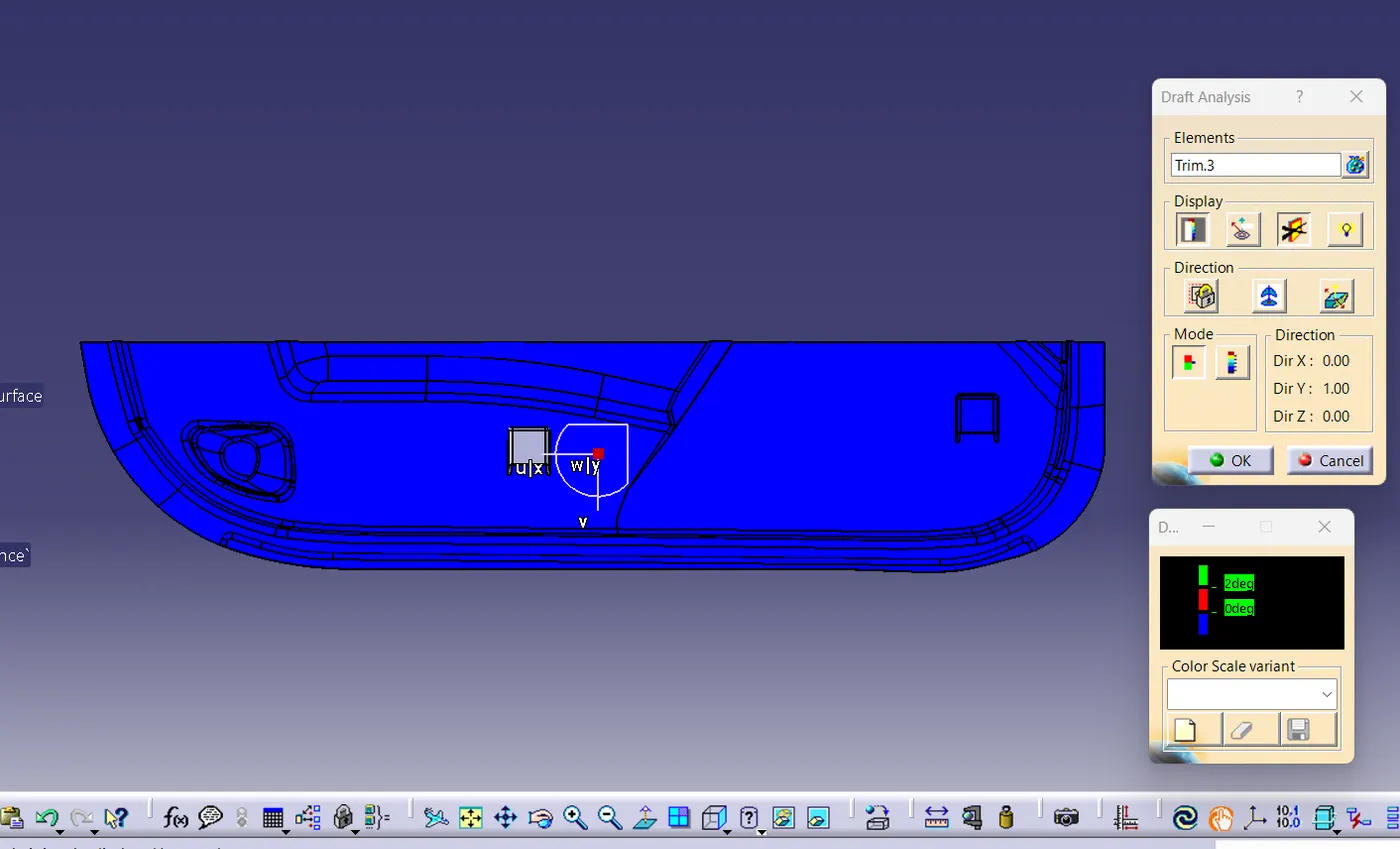
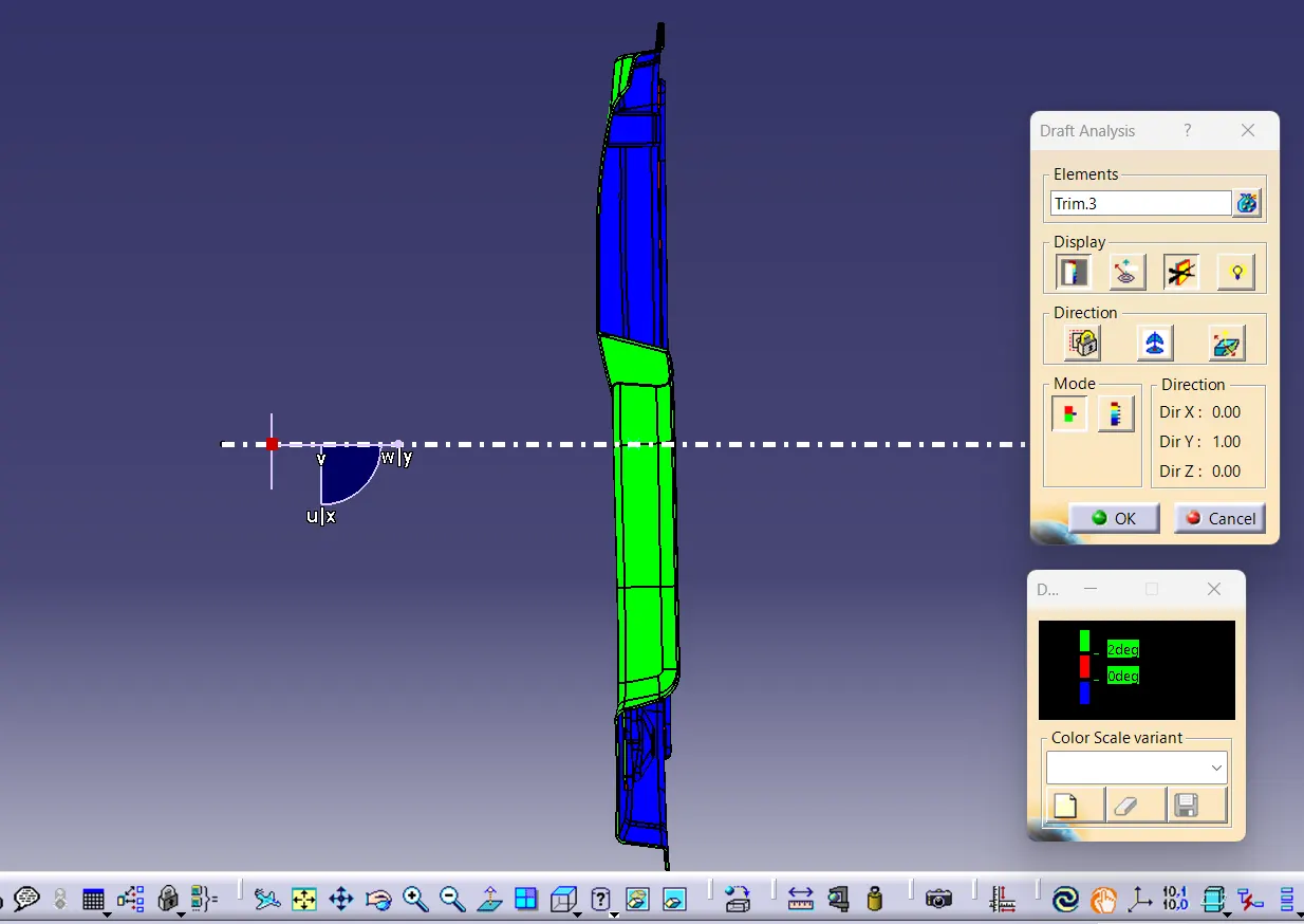
Upon careful inspection we found some regions are not clearing the Draft Angle as shown below
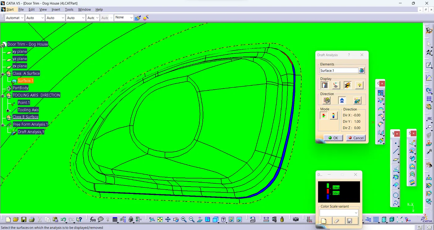
Draft Analysis on Final Component :
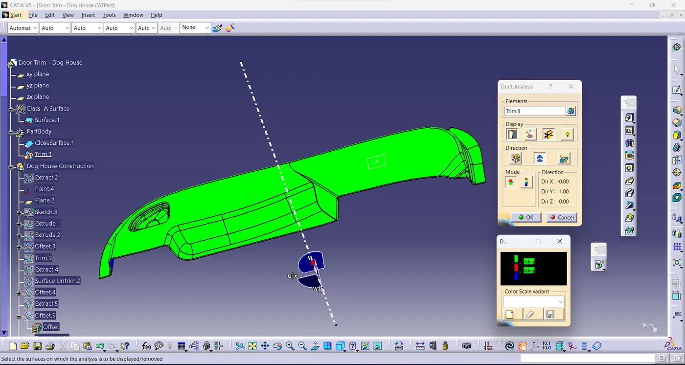
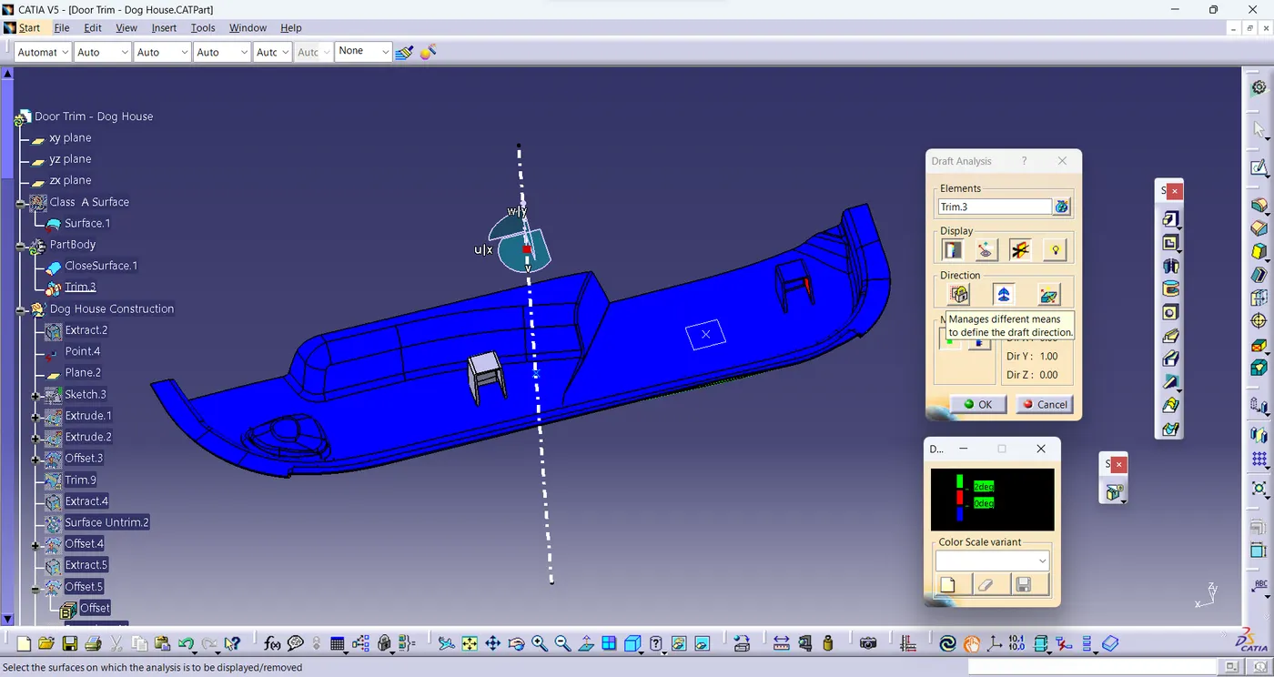
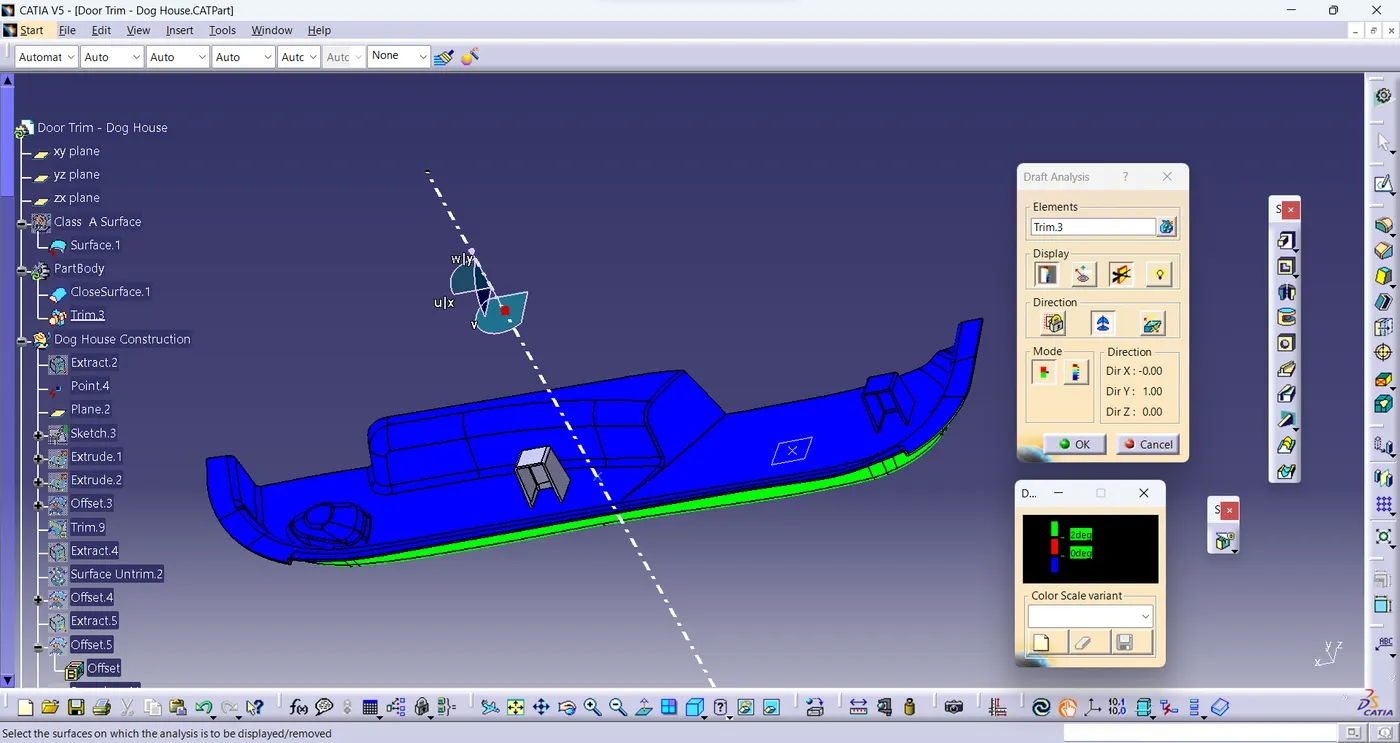
- Screenshots of the completed design in various orientations (Isometric, Front, Side, and Top View)
ISOMETRIC VIEW
FRONT VIEW
SIDE VIEW
TOP VIEW
Dog House Guidelines
- Draft- 1.5 degrees on outer faces & 0.5 degrees inner faces
- Dog House walls
- Part surface
- Bottom of the Dog House
- Wall Thickness
- Height & Width
Design Guidelines for Dof House Creation in this Challenge :
-
Doghouse wall thickness at the intersection of the part wall ( C ) should be 40% or less than the main wall stock ( T ).
-
The height of ( B ) should be between 3.0 – 6.0 mm
- The draft angle with respect to the Main Tooling Axis should be 1.5 degrees & the Side Core Axis should be 0.5 degrees.