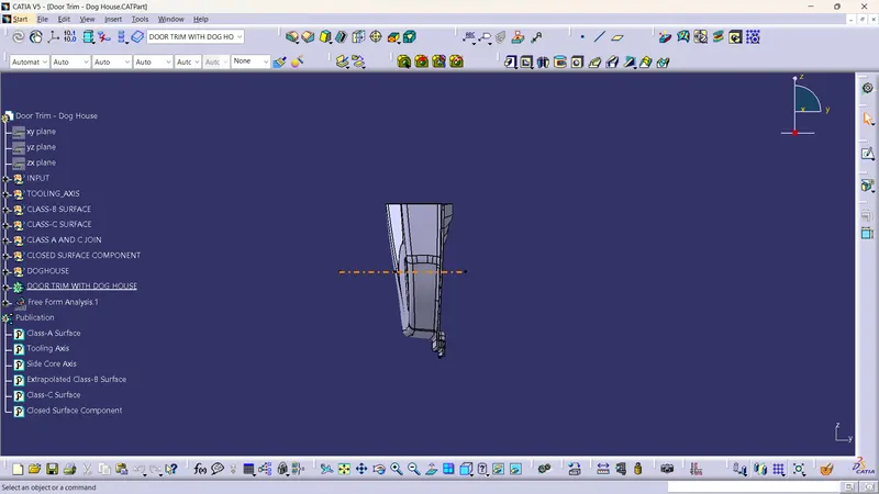
Week 10 - Challenge 2- Attachment Feature Creation (Dog House)
Attachment Feature Creation (DOG HOUSE)
Class-A Surface of the Door Trim provided as input:
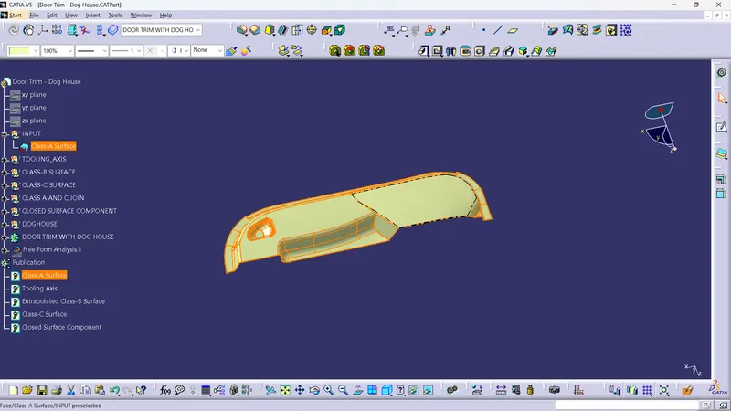
- Tooling Axis Creation:
We first study the Class-A surface from all directions to find the optimum direction to be the Tooling Axis.
X-Direction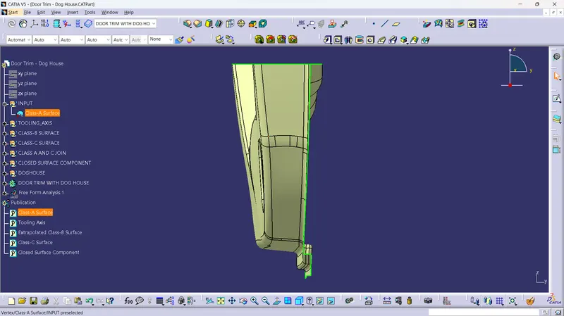
Y-Direction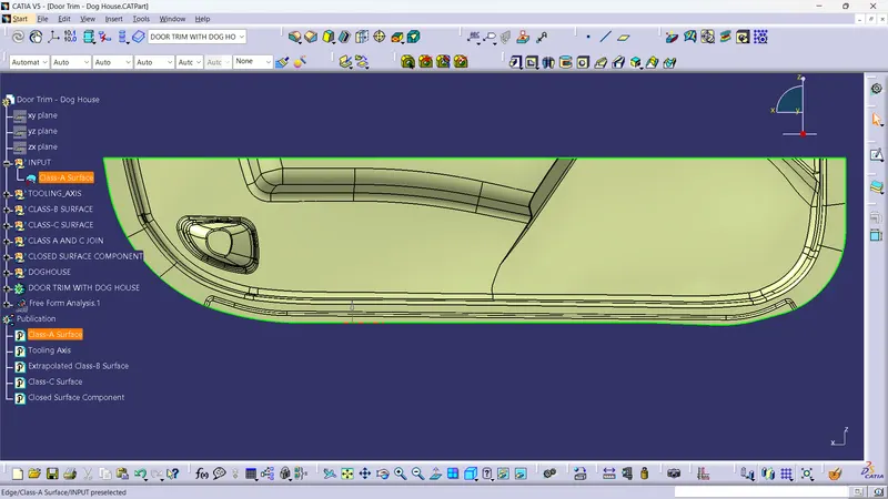
Z-Direction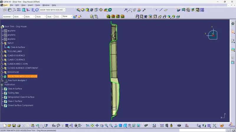
We find that we can see the most surfaces from the Y-direction and therefore choose the Y-direction to be the Tooling Axis.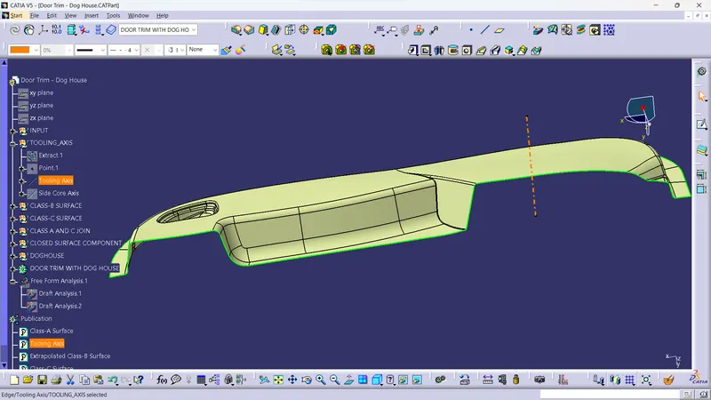
From the Draft Analysis of the Class-A Surface using the tooling axis (image shown later), we find that some surface patches have an angle less than the Draft Angle (3 degrees) with respect to the tooling axis.
When we try to change the angle of the Tooling Axis with respect to the Class-A surface using the bisecting line method, in order to orient the tooling axis in such a way that the problematic surface patches make an angle of more than 3 degrees (Draft Angle) i.e. show up in green, we find that it gives rise to problematic surfaces in other parts of the Class-A surface.
Therefore, we keep the Y-axis as the main Tooling axis. For industrial projects, we can seek help from the Class-A Surface Modeller to provide a Draft angle for the surface patches that might be problematic. - Draft Analysis:
To check if we have selected the Tooling Axis correctly we perform the Draft Analysis. The result of the analysis shows us, using colour codes, which surfaces have an angle lower than the draft angle with respect to the Tooling Axis (in Red).
These surfaces may cause problems when we try to eject the part from the mould.
- Performing Draft Analysis on Class-A Surface using the Tooling Axis (Y-Direction):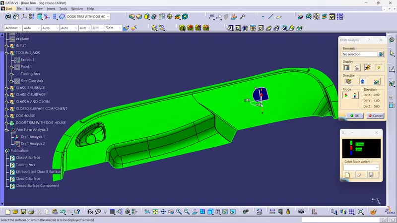
We can see from the image below that there are certain surface patches that are in Red i.e. having draft angle less than 3 degrees.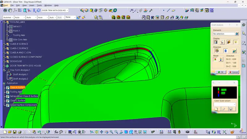
Most of the surface patches are in the Green. There is a small patch that is in the Red, for that, we may need to contact the Class-A modeller and ask them to provide Draft Angle to that surface.
- Performing Draft Analysis on the Closed Surface component using the Tooling Axis: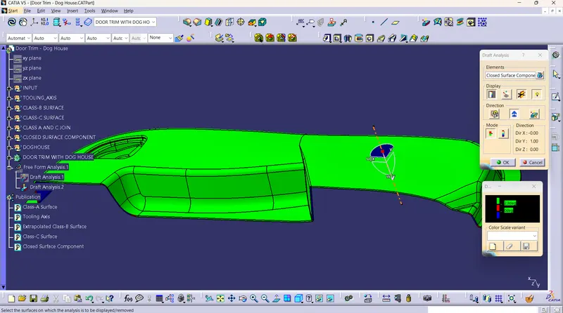
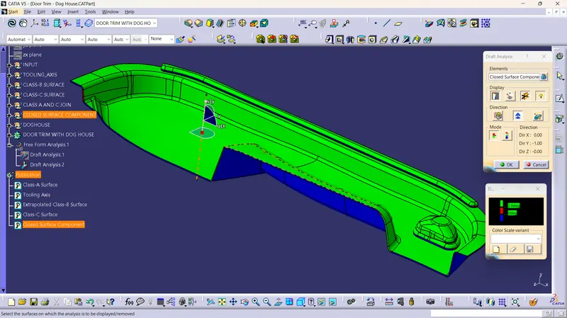
Once we have created the closed surface component using the Class-A, Class-B and Class-C Surfaces we perform the Draft Analysis again. This is done to check that the surfaces we created have the required draft angle i.e. the closed surface can be ejected easily from the mould.
- Finally, we perform Draft Analysis on the Solid Part (with Dog House) using the Tooling Axis and the Side Core Axis: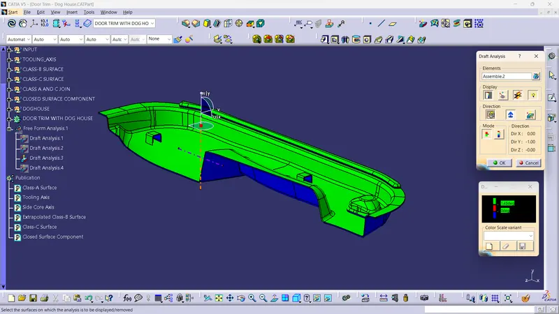
Draft Analysis using the main Tooling Axis shows us that the outside surfaces of the doghouse have the required draft angle (in Green) and can be easily ejected from the mould.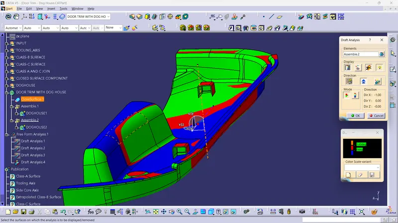
The inner surfaces of the doghouse are created using a Side Core. A Side Core is an additional mould component used to create B-Side features like Doghouses and holes. The Side core axis represents the direction in which the side core moves during the ejection of the part from the mould.
Therefore, we perform a draft analysis on our solid part with respect to the Side Core axis, since the inner faces of the doghouse can only be cleared from the Side Core Axis.
From the above image, we can see that the inner faces have the required draft angle as per the design rules (all in Green) which eases the ejection of the side core without damaging the inner faces of the doghouse.
=> Before finalizing the part, we must also confirm that the B-Side Features follow the Design Rules:
The nominal thickness of the part wall is 2.5mm.
Dog House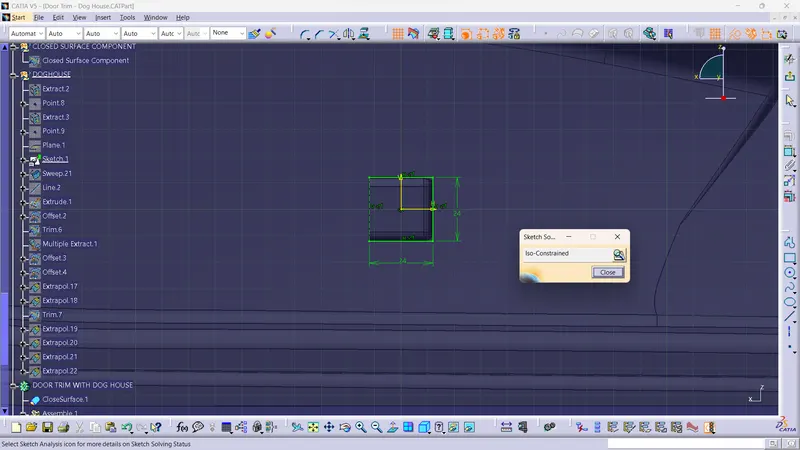
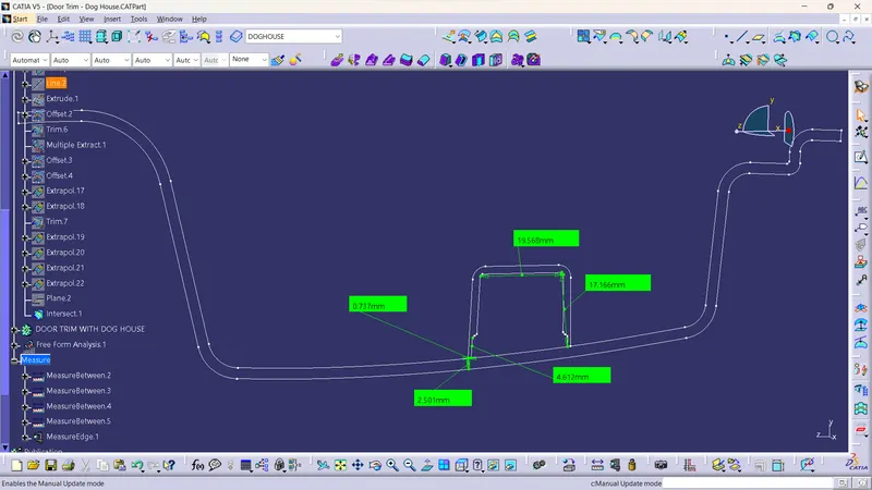
-
Doghouse wall thickness at the intersection of the part wall (C) should be 40% or less than the main wall stock (T) (2.5*0.4 = 1mm): 0.737mm measured.
-
The height of (B) should be between 3.0 – 6.0 mm: 4.612mm measured
- The minimum doghouse width should be 12mm: 19.56mm measured.
- The minimum doghouse height should be 6mm: 17.16mm measured.
- The minimum Draft for a doghouse is 1.5 degrees as confirmed by the Draft Analysis.
Isometric View: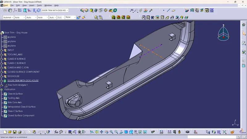
Top View:
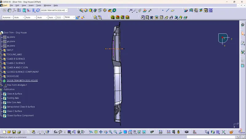
Side View:
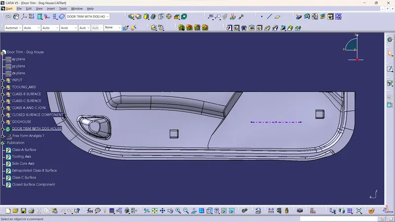
Front View: