Week 10 - Challenge 2- Attachment Feature Creation (Dog House)
AIM
To Create the Dog House for the Door Trim considering the design rules through the given Class-A surface.
THEORY
Tooling Axis
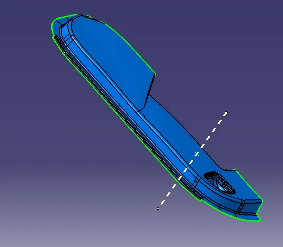
Tooling Axis is the direction in which the mold or core and cavity opens and closes. While designing a component first thing is to define the tooling axis.
Procedure
- Check the connectivity of given Class A Surface i.e no gaps between the surfaces.
- Analyse the component along x,y,z direction and check which is the best possible tooling direction (Here Y)
- Create a point at flat surface by extracting it.
- Draw a line perpendicular to extracted flat surface through the point and that is the tooling axis.
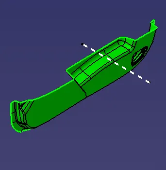
Class A Surface: Class A surface is any of a set of freeform surfaces of high efficiency and quality. In other words, Class A surface is the aesthetic surface.
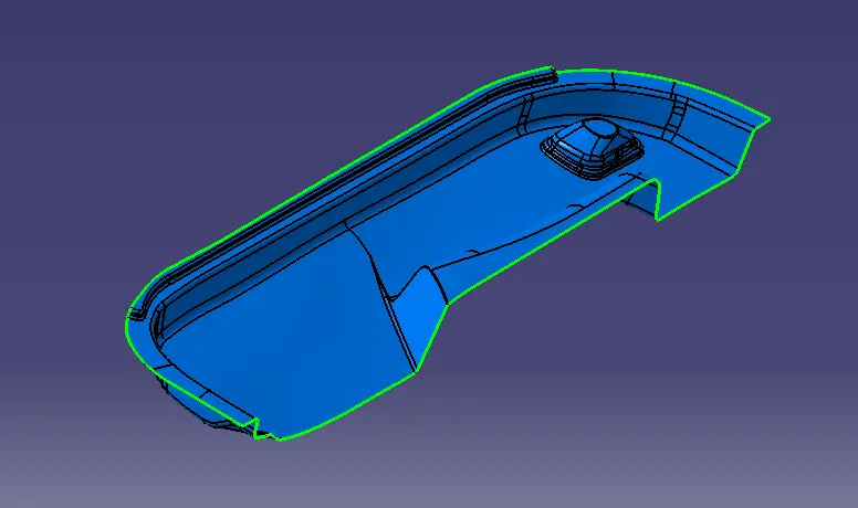
Class B Surface: Class B surface is the thickened suface or engineering surface where all ribs, screw bosses, dog houses etc will come.
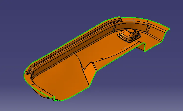
Class C Surface: It is the Surface which joins Class A and Class B surfaces.
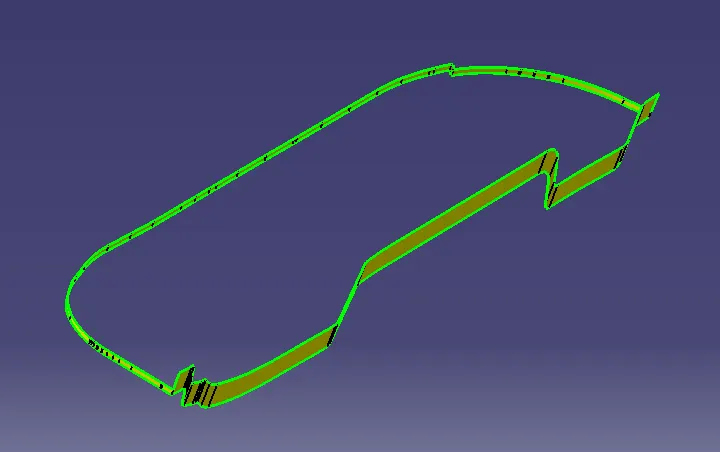
SOFTWARE USED
Catia V5
DESIGN CONSIDERATON
Thickness T : 2.5mm
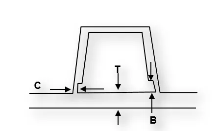
| C | 40%40% of T or ≤≤ T |
| B | 3 - 6 mm |
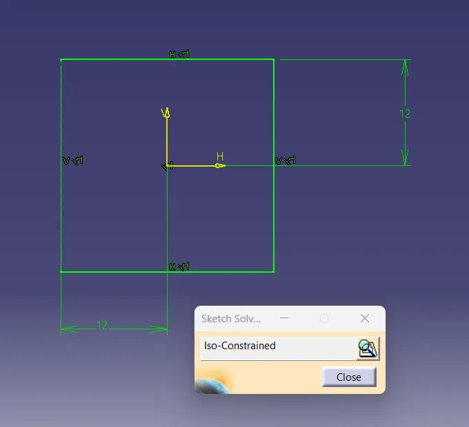
| Width | ≥12≥12 mm |
| Width to Height Ratio | 3:1 |
| Draft | 1.5o1.5� |
DESIGN
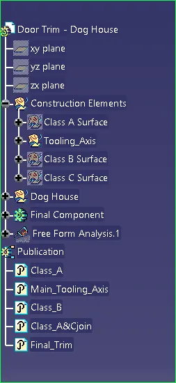
Tree Structure
Tooling Axis
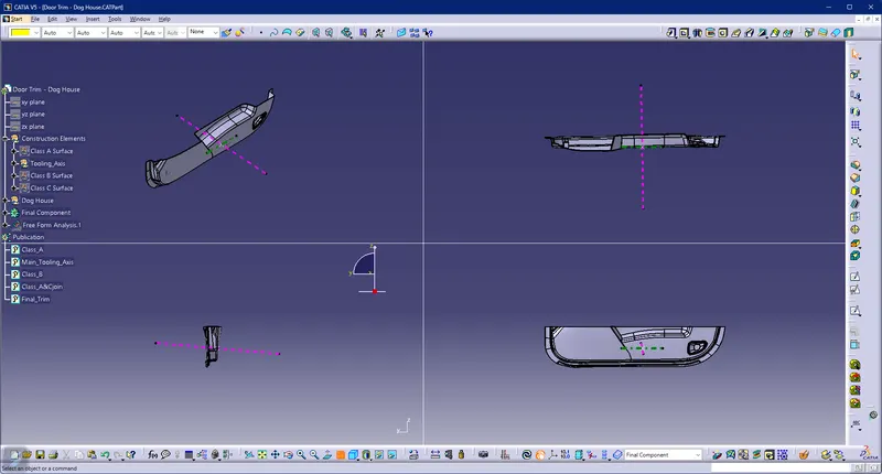
Various Aspects:
Draft Analysis
Class A Surface
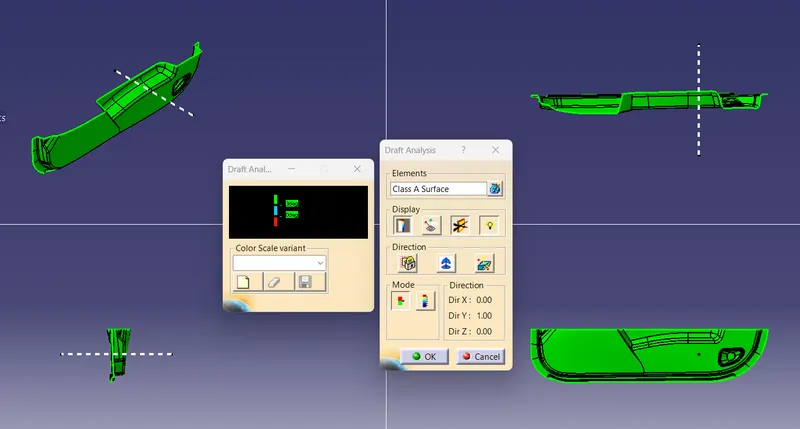
The given Class A Surface is not clearing draft fully, it has some negative draft in some of the areas. So we have to inform the Stylilng team about this, but for this challenge purpose we are proceeding with this surface.
Solid Component
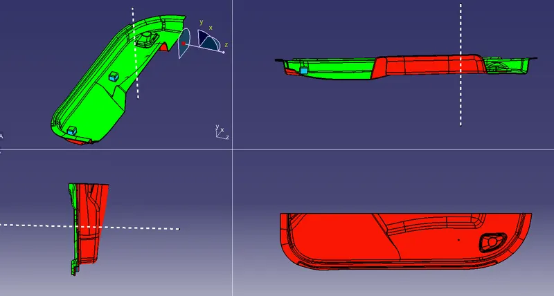
Solid Component Draft Analysis:
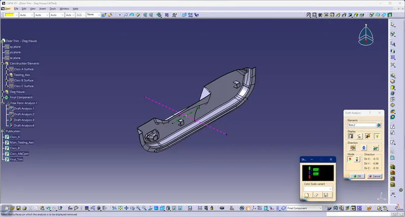
Class A Surface
Class B Surface
Class C Surface
Final Joined Surface
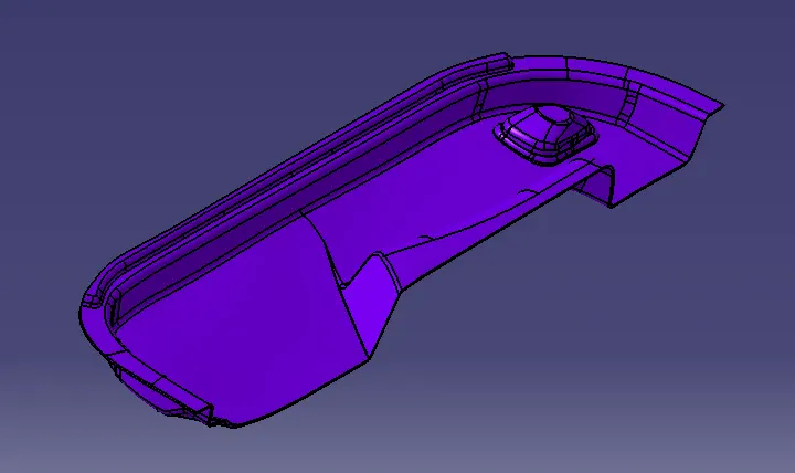
Dog House
Sketch
3D Model
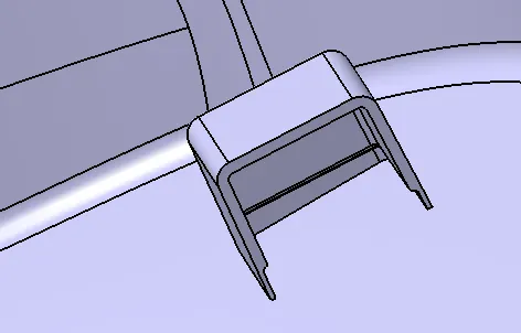
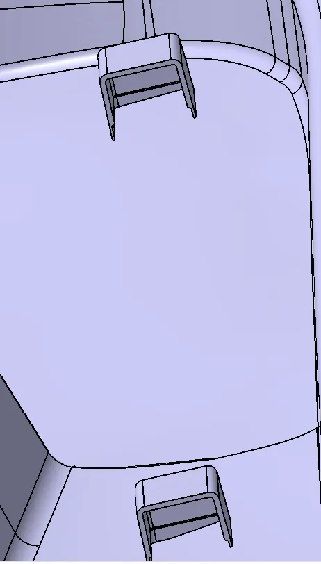
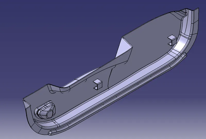
Final Component With Dog House In Various Orientations
Isometric View
Front View
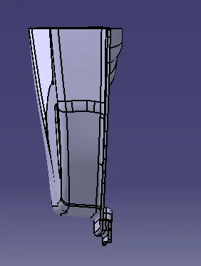
Left Side View
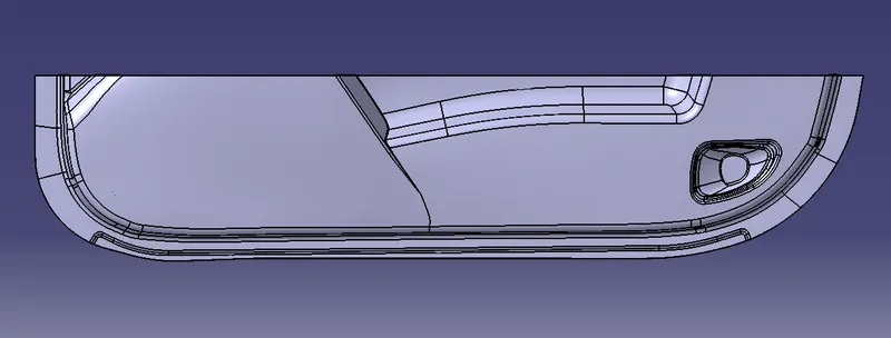
Right Side View
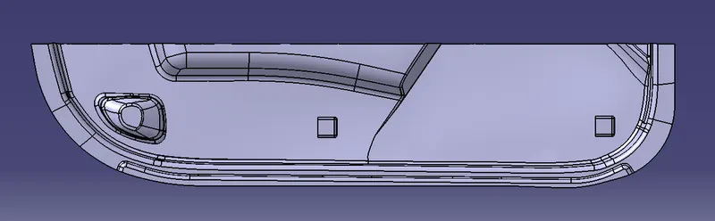
Top View
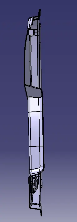
CONCLUSION
Dog House for the Door Trim considering the design rules has been created in Catia.