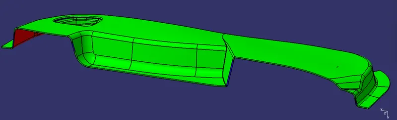
Week 10 - Challenge 2- Attachment Feature Creation (Dog House)
OBJECTIVE:
The main objective of this challenge is to create a 3D solid body and two dog houses as attachment features for it while following the given design guidelines from the above-given class A surface, with the help of a tooling axis of the class A surface. Perform the draft analysis for the solid part body and class A surface .
CHECKING THE INPUT - A SURFACE
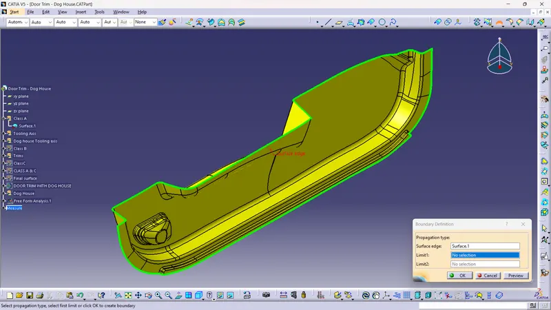
Skin data will be provided to us by the styling team.The A-surface or the styling surface is first checked for any gaps and other issues in its surfaces. This Surface acts as the input surface so any correction to be done should be with approval from the styling team or done by them. A- perfect surface is the one when a boundary is created, the lines are only on the edges of a component and its holes or cutouts as shown below.
PROCEDURE FOR CREATING THE TOOLING AXIS
Tooling axis is the direction in which a core or cavity of mold opens. This Axis is very important to determine the orientation of the component in mold, core and cavity design.
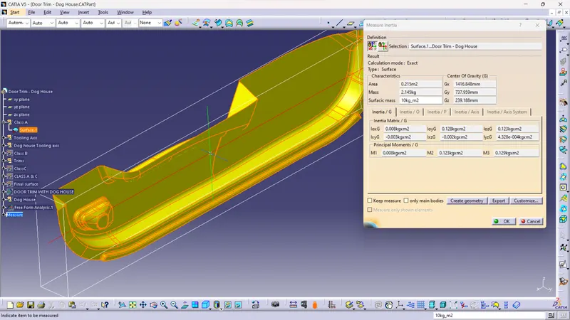
The tooling axis is created by the inertia method by using the steps as follow
-
Click “Measure inertia” and select the A-surface
-
Click “Create geometry” in the Measure Inertia window.
-
In the Creation of Geometry window, select Non-associative geometry.
-
Click “Center of Gravity”
-
The Inertia point is created.
-
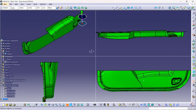
The component is viewed in all axes namely X,Y and Z.
-
It is determined that the X-axis will be the direction for the Tooling axis and a line is created Using the CG point and X-direction as direction of the line
DRAFT ANALYSIS OF A SURFACE:
- Draft analysis of the surface is carried to check if the surface or part can be manufactured with the required draft angle.
- Draft angle is needed for the component to clear the core and cavity surface as it would have shrunk towards the center while cooling.
- The draft angle in this design is 3 degrees. As A surface is a single surface there won't be much difference in color. The draft analysis of A-surface is shown below.
CREATION OF B-SURFACE:
The A-surface is offsetted by 2.5mm as it is the thickness required.The offset surface is the B-surface but had some issues like in some areas shown in below images.
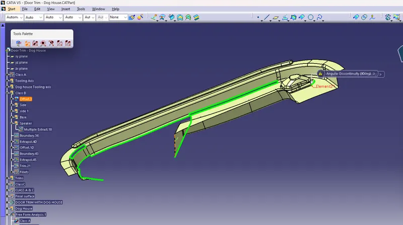
- The Areas where the B-surface has issues are corrected by closing them using commands like Multi section,Sweep,Offset and extract.
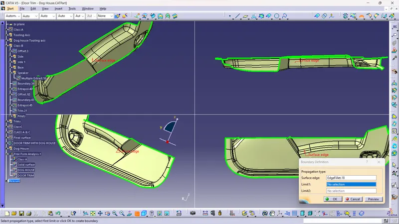
- Finally all the created surfaces are trimmed or joined together with offset surfaces done earlier. This created a single single surface which will act as the final B-surface.
CREATION OF C-SURFACE:
- We'll create the Class C Surface with respect to the Class A Surface and provide draft angles to those surfaces that are parallel to the Main Tooling Axis.
- Surfaces at the bottom won't be needing any draft angle as they'll get cleared by the core itself. To create the Class C Surface we have to use various commands such as Sweep with Reference Surface and With Draft Direction depending upon the necessity and at places where it'll be difficult for us to create a surface using Sweep, we'll use Multi-Sections Surface to create those surfaces. The draft angle will be 3 degrees.
- Using Sweep Command with Draft Direction to create the C Surface:
CREATION OF CLOSED BODY:
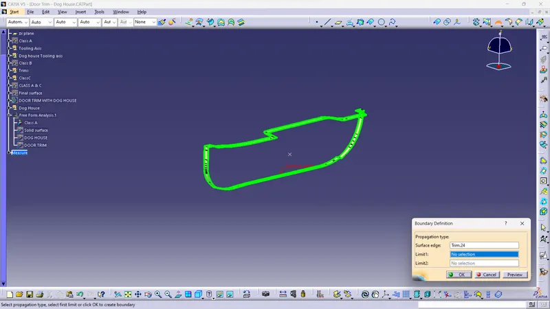
All the surfaces (A,B,C) are joined together to form a closed body.
Boundary is selected and the body is picked. Since an error popped up it can be understood that all surfaces are joined with each other to form a proper closed surface body.
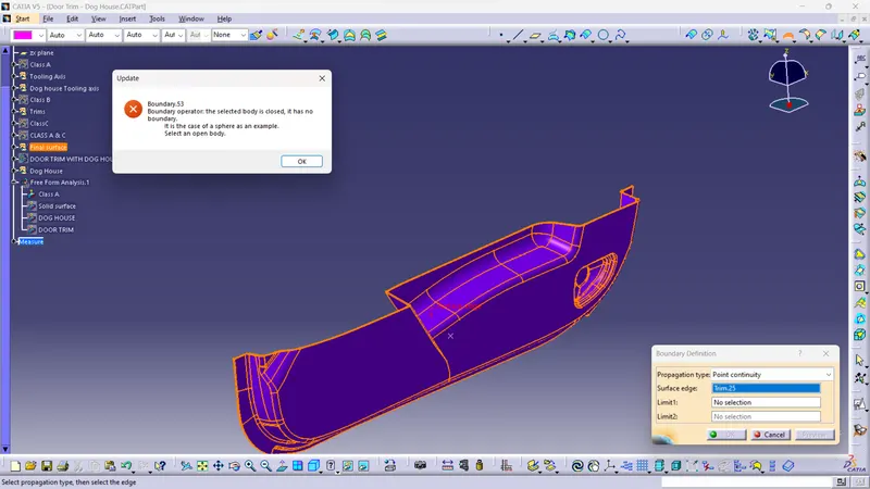
From the above image, we can see that the final closed body doesn't have any boundaries, and hence our final closed body is obtained successfully.
Finally, we'll go to the Part Workbench and use the option 'Closed Surface' from the 'Surface-based Features' toolbar to convert the final trimmed body into a solid body as shown below:
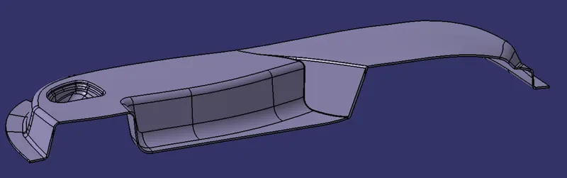
PROCEDURE TO CREATE THE DOGHOUSE:
Reference Image provided for the construction of two doghouses:
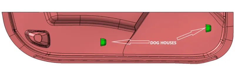
It is just a reference image and doesn't exactly adhere to all the design rules but we have to take the reference image into account to create these doghouses on our plastic component.
DOG HOUSE
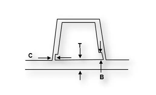
-
Doghouse wall thickness at the intersection of the part wall ( C ) should be 40% or less than the main wall stock ( T ).
-
The height of ( B ) should be between 3.0 – 6.0 mm
First, we'll begin by creating the sketch for the doghouse as shown below:
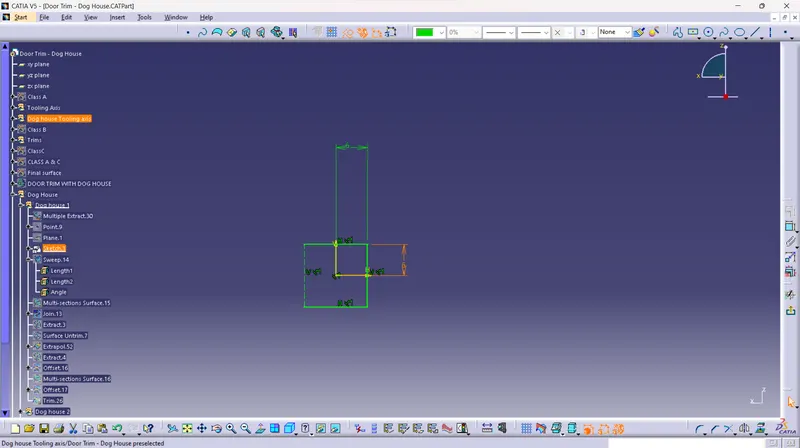
From the sketch, we can see that the width of the doghouse is more than 12mm which is one of the design rules. We cannot go below that value.
Then, we'll use the Sweep Command with the Draft Direction to provide a draft angle of 3 degrees with respect to the Main Tooling Axis as shown below:
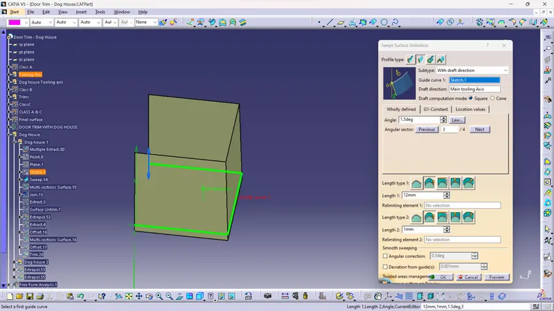
From the above image, we can see that 1.5 degrees draft angle is provided to the sweep surface.
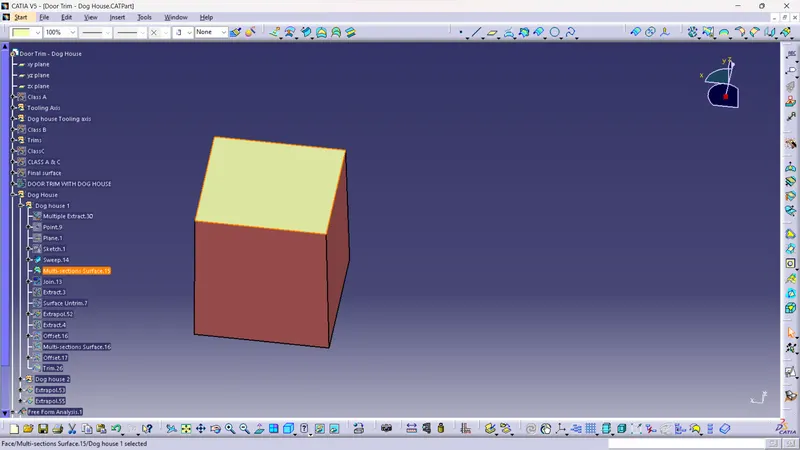
After this, we're going to use the Multi-Sections Surface command to create the top face of the doghouse as shown below and join it with the sweep surface
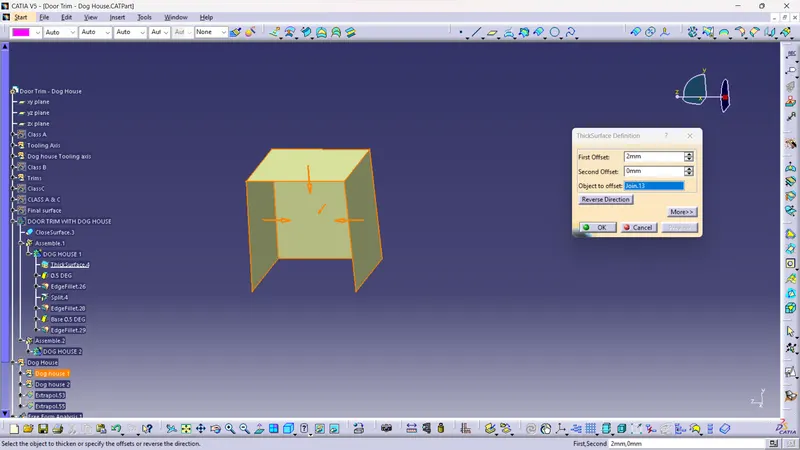
Now we're going to move on to the Part Workbench and use the Thick Surface command from the Surface-based Features toolbar to thicken the surfaces by 2mm as shown below:
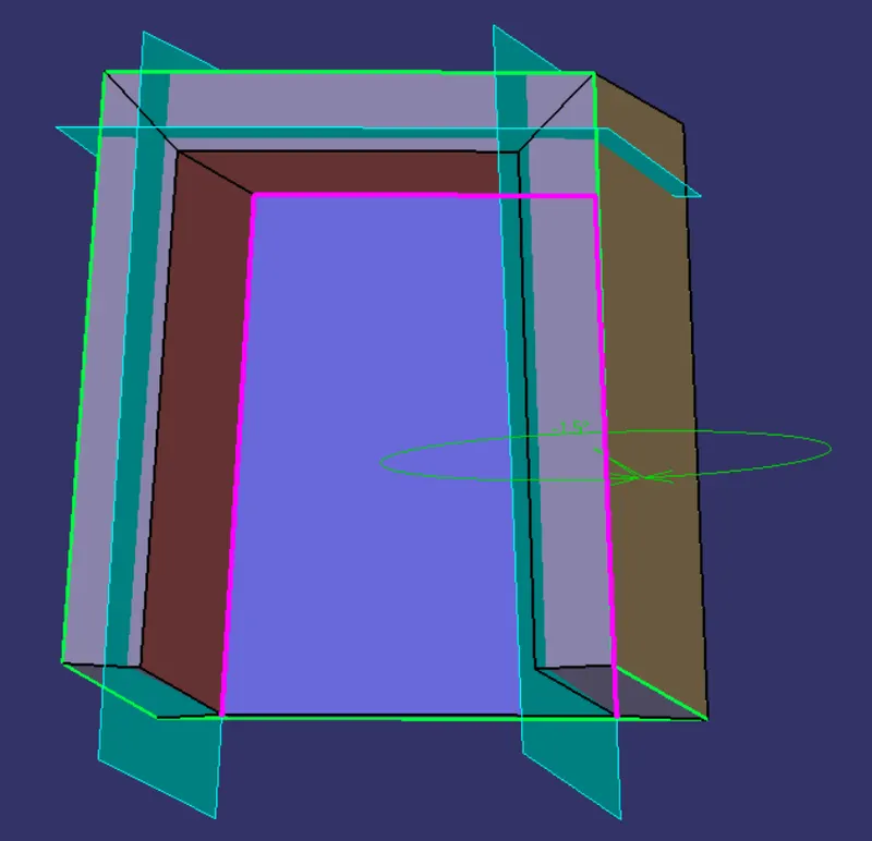
Then we're going to provide a draft angle of 1.5 degrees to all the adjacent faces as shown below using the Draft Command in the Part Workbench:
After this, we're going to remove the material from the lower section of the doghouse for coring and to do that we going to use create a base surface of the doghouse using the Multi-Section Surface command and then offset it by 4mm. Then, we used the Multi-extract command to extract the inner faces of the doghouse and trim it as shown below:
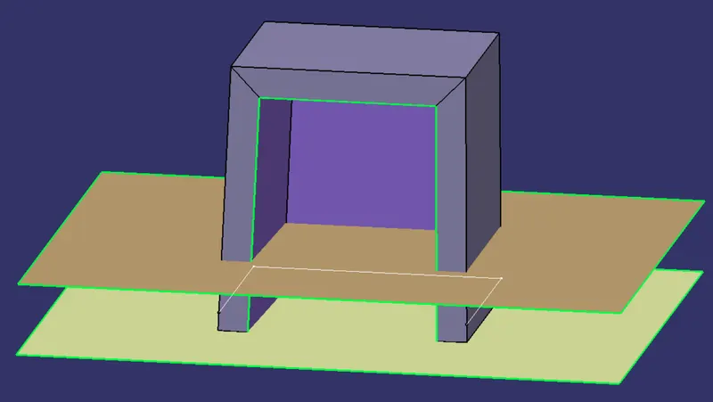
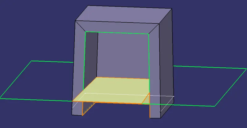
Now, according to the design rule, the thickness of the coring section's wall should be 40% value of our part's thickness and 40% of 2.5 is 1mm and our current wall thickness of the doghouse is 1.685mm. Hence, we're going to offset this trimmed surface by 0.685mm and extrapolate it so that we can use the Split Command from the Park Workbench to remove material from the doghouse as shown below:
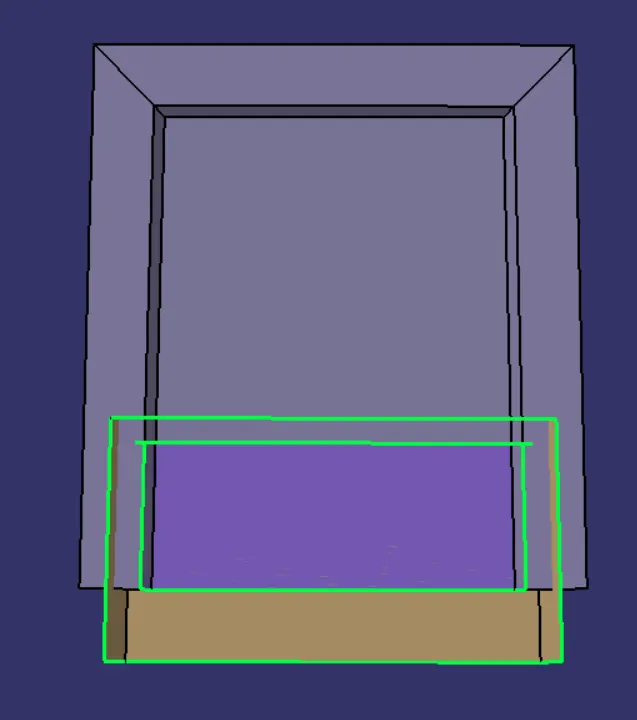
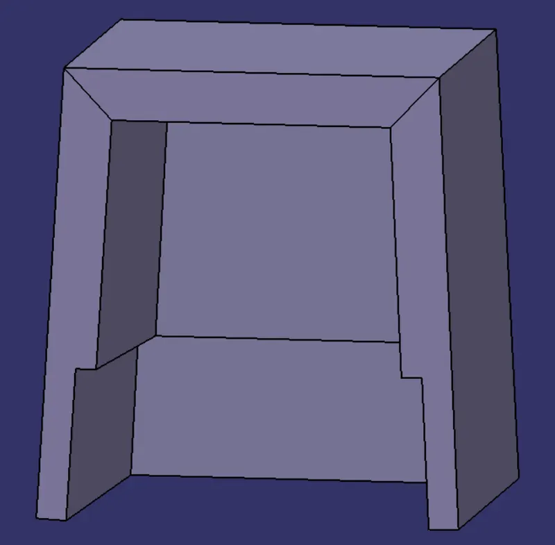
After that, we'll provide a draft angle of 1.5 degrees to the newly formed surface made using the coring operation as shown below:
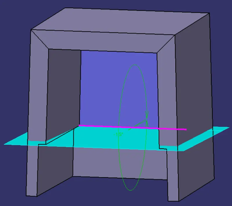
Finally, we're going to provide all the necessary edge fillets on the required surfaces following the design rules as shown below:
Finally, we're going to provide all the necessary edge fillets on the required surfaces following the design rules as shown below:
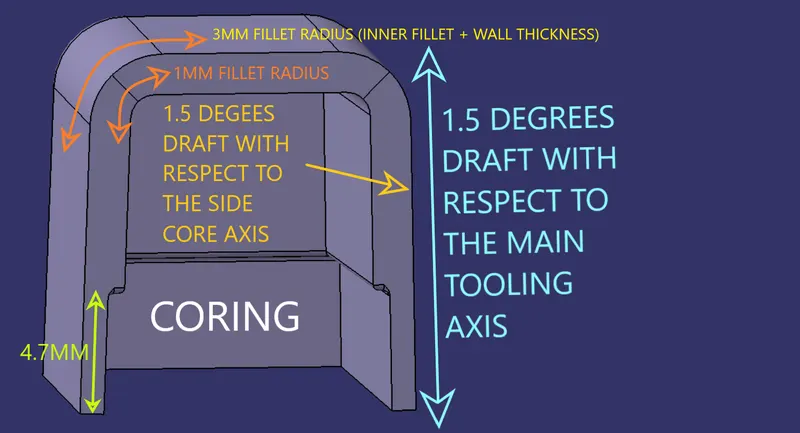
Hence, our doghouse is finally complete and we'll make the second house following the same design rules.
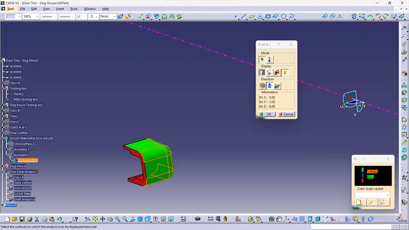
Now, we'll perform a draft analysis operation on our doghouse to make sure that is clearing along the required tooling axes as shown below:
DRAFT ANALYSIS WITH RESPECT TO THE MAIN TOOLING AXIS:
First, we'll place the compass on the Main Tooling Axis as shown below:
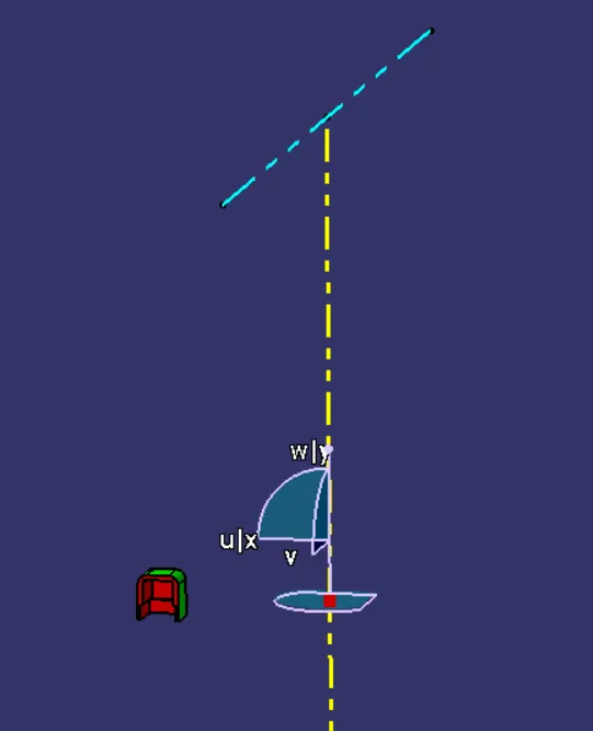
Then, we'll set the value to 1.45 degrees as the required draft angle was 1.5degrees and inspect it as shown below:
DRAFT ANALYSIS WITH RESPECT TO THE SIDE CORE AXIS:
Now, the inner section of the doghouse is needed to clear along the side core axis and hence now we'll place the compass on the Side Core Axis and perform the draft analysis as
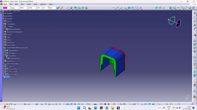
From the above image, we can see that the draft analysis was successful and hence our doghouse will get cleared along both the Main Tooling Axis as well as the Side Core Axis.
Now, using Boolean Operations, we're going to assemble these doghouses with our main plastic component and create the final part as shown below:
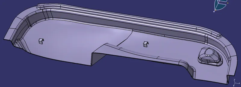
DRAFT ANALYSIS ON THE FINAL PLASTIC COMPONENT WITH ATTACHMENT FEATURES:
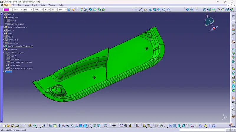
3D VIEWS OF THE FINAL PART WITH PROPER COLOR CODE OF THE DRAFT ANGLE IN VARIOUS ORIENTATIONS:
1. FRONT VIEW:
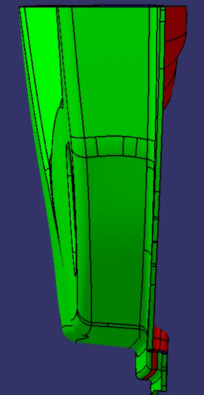
2. TOP VIEW:

3. ISOMETRIC VIEW: