Week 10 - Challenge 2- Attachment Feature Creation (Dog House)
AIM: Create the Dog House for the Door Trim considering the design rules.
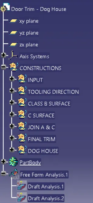
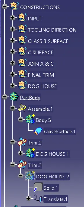
Objective: In this project we are going to see dog house for the Door Trim considering all the design rules using the different tool in CATIA V5 software. Ensure proper tree structure and all the sketch should be ISO constrained.
Thickness of the part = 2.5mm
For Close Surface Design
- Open Clss A Surface
- Create Tooling Axis
- Create Class B Surface
- Create Class C Surface
- Join Class A & C Surface
- Trim joint class A&C with Class B
- Check Close Surface
- Then Make it solid body
General guidelines for Dog House
-
Doghouse wall thickness at the intersection of the part wall ( C ) should be 40% or less than the main wall stock ( T ).
-
The height of ( B ) should be between 3.0 – 6.0 mm
DOG HOUSE DESIGN
Before going on to the Dog House design we will have to create close surface of given input class A surface.
TOOLING AXIS:
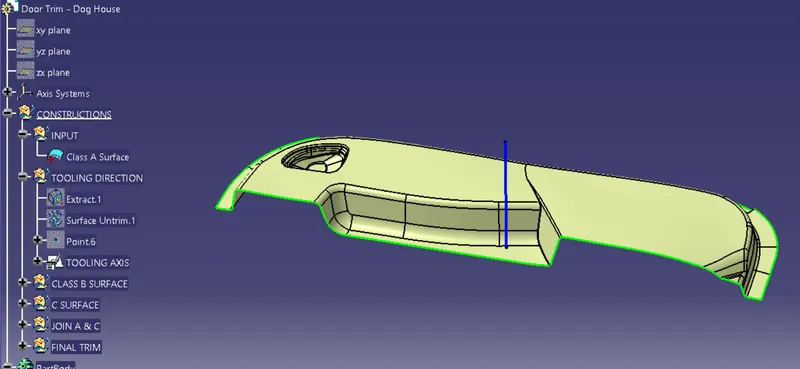
First we have to observe and study the class A surface to create the "Tooling Axis" for the component, and for the above given door handle. Here i use bisecting method to create tooling axis by the use of side wall surface. Initially, I create a dummy tooling axis on y-axis by considering the reference point created on the any curve of the door handle. When we create axis on door handle through bisecting method, the axis coinside with the dummy axis but first we have to check class A surface making an angle direction inbetween 0-3 degree by draft analysis method.
DRAFT ANALYSIS:
To perform draft analysis, click on Insert>Analysis>Feature Draft Analysis
Once the draft analysis toolbar is opened, go to the display block and select the 'Analysis under the running point' command to check the angle for different sides (walls and inclined plane angles) on the class A surface. The color scale on the bottom visualizes, whether the draft angle meets the requirements or not (3 deg) by indicating the colors Green, Blue and Red. Once the draft angle analysis was done, we need to align and fix the compass to the tooling axis of the class A surface.
To align and fix the compass to the tooling axis, go to the Direction block in the draft analysis toolbar and click on the 'Use the compass to define the new current draft direction option (or just click on the compass symbol). Now bring the compass to the surface and align it to the tooling axis of the class A surface and click on the lock symbol beside the compass in the direction block. Once we click on 'ok' on the draft analysis toolbar, we can finish the draft analysis process.
NOTE: First check shading is in material mode (Go to the customise view parameter)
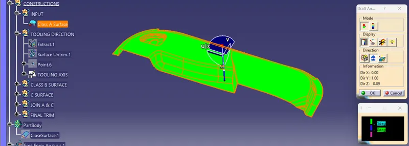
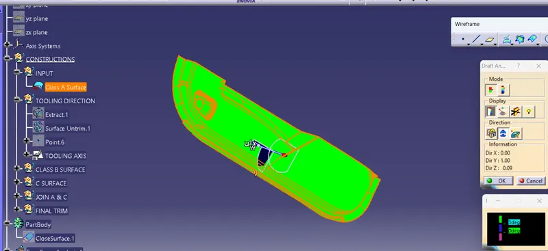
We can clearly see in the above figure draft angle is set to be 3 degree and all the surfaces are in green color it means we can consider tooling axis is now main tooling axis.
CLASS B SURFACE:
To create te class-B surfeace, I will go through the direct offset method becouse here the given door trim surface are very difficult to find out where to start class-B surface so to do that we have to directly offset it upto desired thickness and then we will go through, like some part are missing in offset surface. So that surface we have to fill by using extraction, untrimmed, extrapolation, trimming, joinning tool in surface design workbench etc.
Here it showing warning that some element or patches are missing so we have to click "OK". Offset surface looks like
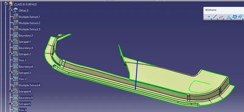
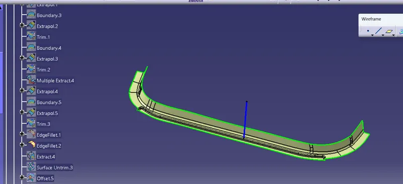
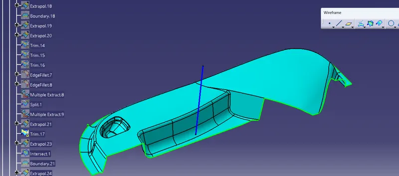
First i go to the lower patches, where i do extraction, extrapolation, create boundy, trimming
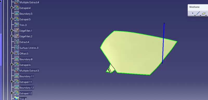
Now i work on left side patches which is missing in class B surface offset
Here i first extract some surface part from offset class B surface
Then work on side wall of offset surface
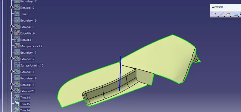
Trim with lower patches
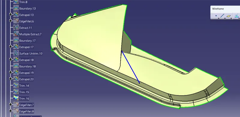
Now we have to add pocket surface (B SURFACE)
CLASS C SURFACE
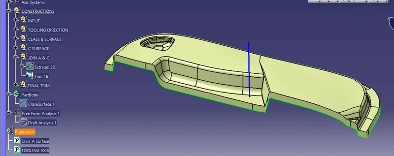
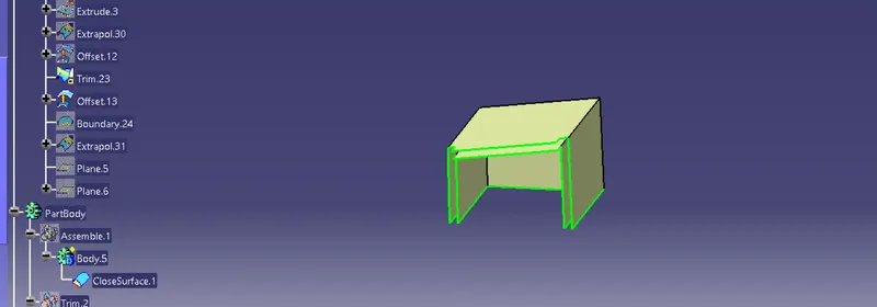
It is the combination of Class A, Class B and Class C surfaces. To create a class C surface, I used the sweep command by considering the outer boundary of the class A surface. In the sweep command, go to the 'line' command in the 'profile' block and the subtype is 'with draft direction'. Now select the outer boundary and tooling axis, give 3 deg in the angle and select the direction to sweep, in this condition the class B surface is under the class A surface so select the inside down arrow to sweep. Now I joined all the sweeped surfaces by using the 'join' command and then I trimmed the Class A, Class B and Class C surfaces to make a closed surface, to make a Solid body.
Boundary creation and Sweep command:
Here we use one by one sweep and boundry command becouse there is sharp edge in the class A.
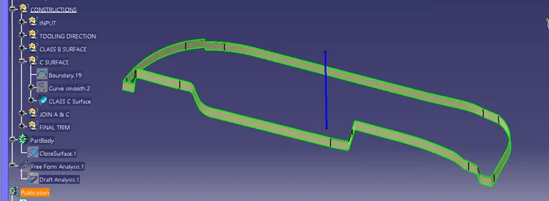
Join class C with class A surface
FINAL TRIM Class B with Joined Class A & C
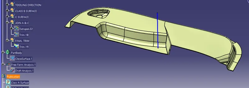
Now we have to check boundry of final trim, below we can clearly see we get error it means final trim is fully connected
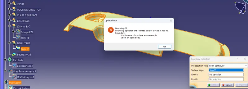
Now make it solid
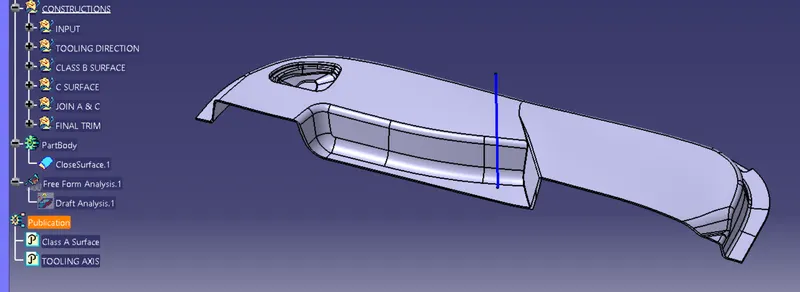
DOG HOUSE
Dog house is an engineering feature used in plastic trim design. Dog houses are used as supporting feature. Sometimes other engineering features like snaps, locators etc. are mounded on them to increase their strength. Dog houses are subjected to draft analysis to prevent breakage of the component during ejection from mould cavity. Dog house and other engineering components are built on B-surface.
Dog House design consideration for plastics:
- Dog House wall thickness at the intersection of the part wall C should be 40% or less than the main wall stock (T).
- The height of B should be between 3.0 – 6.0 mm
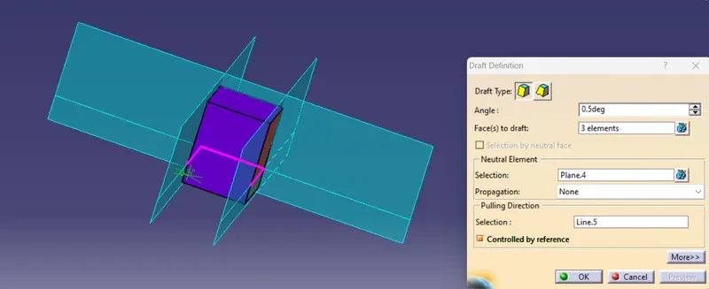
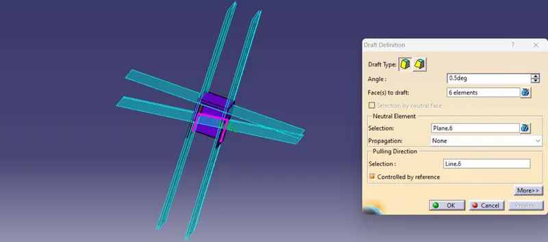
- Draft angle at the wall is 0.5 degree and
- Draft analysis should be 3 deg.
Dog House Creation
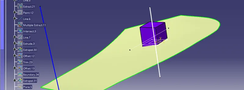
Extract surface and create point on that surface
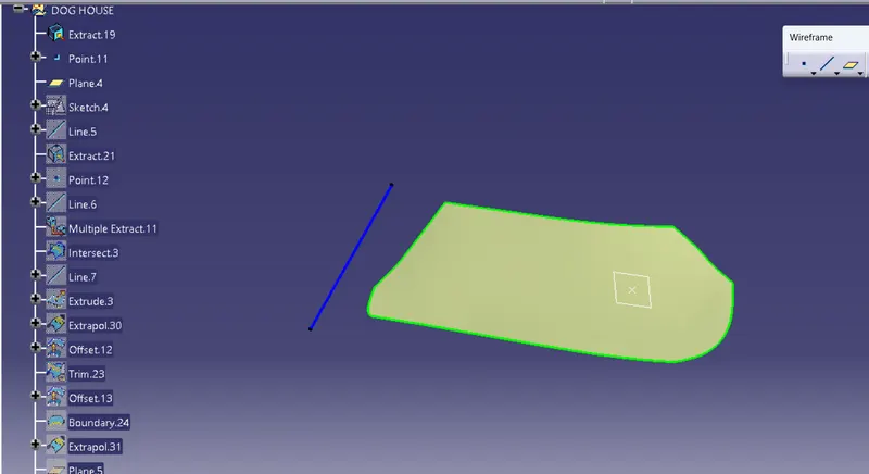
Dog House sketch

Pad it upto 25mm and 5mm buttom side
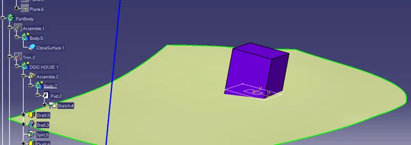
Creat axis for drafing
Draft dog house 0.5 degree
Use shell command, give 2.5mm thickness
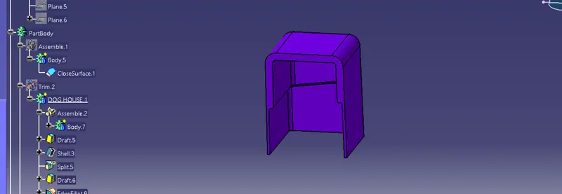
Create CORE and offset it
Split from the bosy and then make the core
Draft for CORING
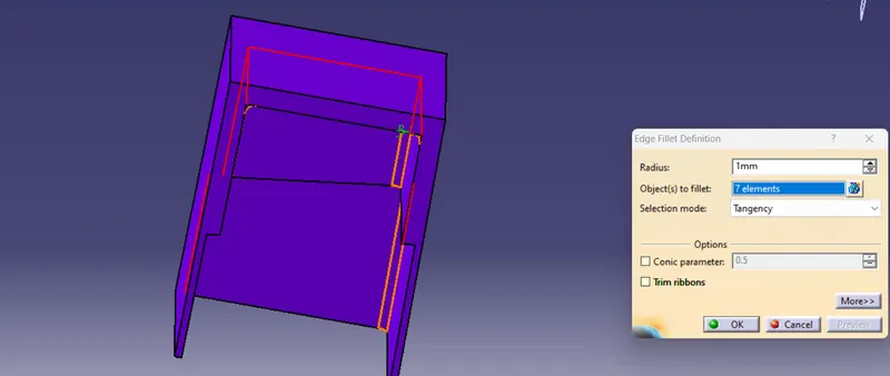
Give fillets
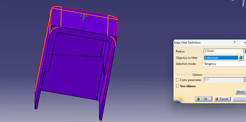
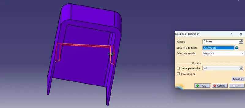
Attach with partbody and trim them
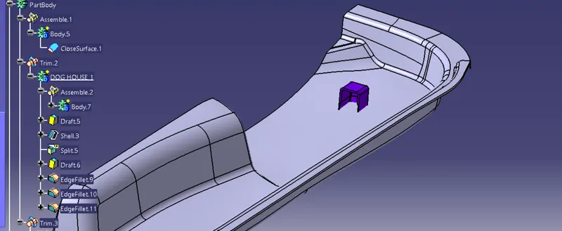
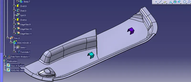
By the use of COPY PASTE we can use and make another dog house and then translate according to the desired position
Draft analysis
Once the draft analysis toolbar is opened, go to the display block and select the 'Analysis under the running point' command to check the angle for different sides (walls and inclined plane angles) on the class A surface. The color scale on the bottom visualizes, whether the draft angle meets the requirements or not (3 deg) by indicating the colors Green, Blue and Red.
To align and fix the compass to the tooling axis, go to the Direction block in the draft analysis toolbar and click on the 'Use the compass to define the new current draft direction option (or just click on the compass symbol). Now bring the compass to the surface and align it to the tooling axis of the class A surface and click on the lock symbol beside the compass in the direction block. Once we click on 'ok' on the draft analysis toolbar, we can finish the draft analysis process.
NOTE: First check shading is in material mode (Go to the customise view parameter)
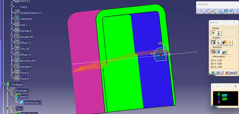
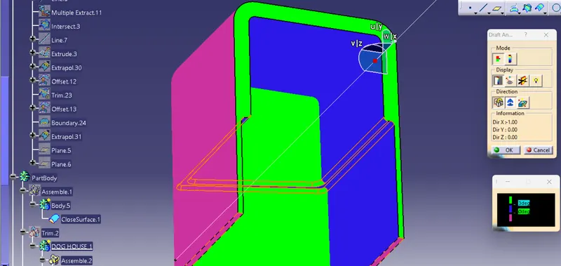
NOTE: Here we can see that drafting on the dog house is perfact. There is no error
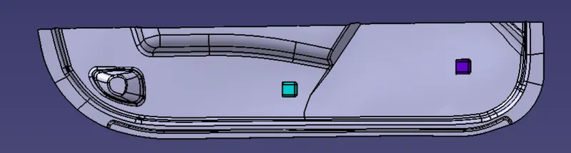
FINAL DOG HOUSE WITH DOOR TRIM
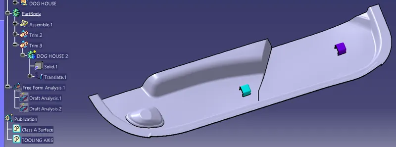
ISOMETRIC VIEW
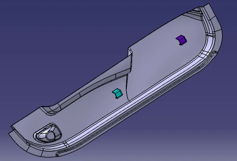
FRONT VIEW
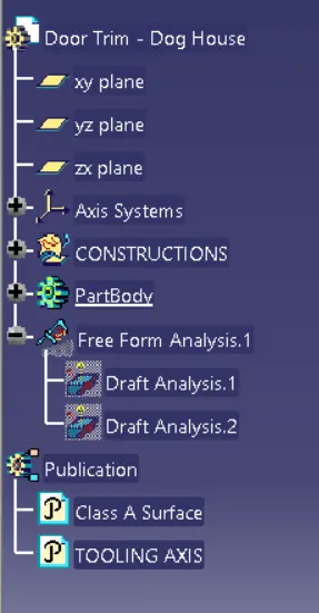
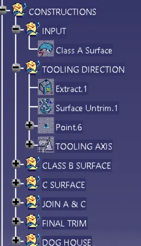
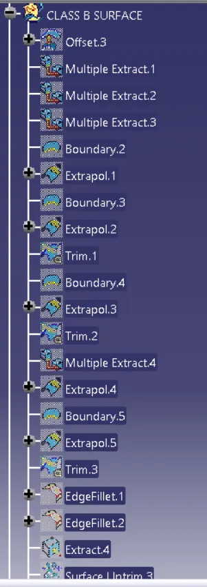
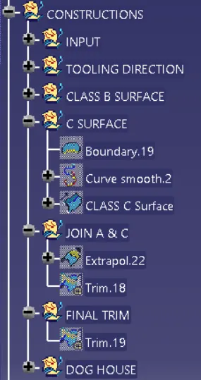
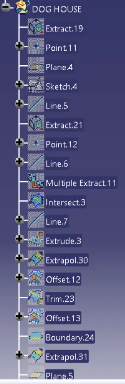
TREE STRUCTURE
CONCLUSIONS
Here we studied Dog House where we use different tools in surface design and part design workbench in CATIA V5 software. In this project first we create solid body of given input class A surface and then create Dog House on solid body, also analyse the draft.