Week 10 Challenge
AIM-:1)What all checks need to be followed in design of well foundation regarding the stability and the design. List out all the necessary clauses from IRC codes applicable.
What are the limits in ULS and SLS for design of a RCC component. Define the limit states and the factors in it as per IRC 112.
Also mention shear checks . what is the difference in shear with/without reinforcement.
ANS-:checks need to be followed in design of well foundation regarding the stability and the design-:
All the checks are considerd from the IRC 78 codes.
- Clause 706.1 for Loads, Forces and their combination.
- Clause 706.2 for Horizontal Forces at Bearing Level.
- Clause 706.3 for Base pressure check
- Clause 706.3.1.1 for Factor of safety.
- Clause 706.3.2.2 for Allowable settlement/differential settlement.
- Clause 706.3.3 for No tension shall be permitted under any combination of loads on the soil.
- Clause 706.3.4 for Factor of safety for stability.
- Clause 708.2 for Well stening design.
- Clause 708.5 for Tilts and shifts.
What are the limits in ULS and SLS for the design of an RCC component? Define the limit states and the factors in it as per IRC 112
Two basic groups of limit states are considered
- Ultimate Limit States (ULS):- These limit states cover static equilibrium and failure of structural elements or structure as a whole, when acted upon by 'ultimate design loads'.
- Serviceability Limit States (SLS):- These limit states deal with the condition of the structure subjected to influence of 'serviceability design loads'. These conditions include level of internal stress, fatigue failure, deflection, damage to structural elements such as cracking, and discomfort to users due to vibrations.
According to IRC:112-2020 following are the limits in ULS for the design of an RCC component.
Limit states (Ultimate limit state), section 5
- Limit state of equilibrium
- Limit state of strenght.
Ultimate limit state of linear element for bending and axial forces, section 8.
- Strain and Stress Distribution at Ultimate Limit State.
- Biaxial Bending
Ultimate Limit State of Two and Three Dimensional Elements for Out of Plane and in Plane Loading Effects, section 9.
Ultimate Limit State of Shear, Punching Shear and Torsion, section 10.
- Design of Flexural Members for Shear.
- Design for Punching Shear.
- Torsion.
Ultimate Limit State of Induced Deformation, section 11.
According to IRC:112-2020 following are the limits in SLS for the design of an RCC component.
Limit states (Serviceability limit state), section 5
- Limit state of internal stress.
- Limit state of crack control.
- Limit state of deformation.
- Limit state of vibration.
- Limit state of fatigue.
Serviceability limit state, section 5
- Stress Limitation.
- Limit State of Cracking.
- Limit State of Deflection.
Shear Checks :-
A shear test is designed to apply stress to a test sample so that it experiences a sliding failure along a plane that is parallel to the forces applied.
All the clause related to shear checks are mentioned in section 10 of IRC:112 ( Ultimate limte state of shear, punching shear and torsion ).
Difference in shear with/without reinforcement :-
- Whenever the value of actual shear stress exceeds the permissible shear stress of the concrete used, the shear reinforcement must be provided. The purpose of shear reinforcement is to prevent failure in shear, and to increase beam ductility and subsequently the likelihood of sudden failure will be reduced.
- Shear reinforcement is required to prevent propagation of diagonal cracks. The diagonal tension cracks develop in the beam, when the strength of the beam in diagonal tension is less than the strength in flexural tension. On this type of failure, the cracks start to develop due to the flexure at mid-span.
Que) How to check steining thickness and its steel.What will be the change in PCC and RCC steining.
ANS-:
Following are the calculation which is use to determine the steining thickness which is mention in IRC:78 clause no 708.2.3.1
Formula :- h=Kd √l�
h = minimum thickness of steining in m
d = external diameter of circular well of dumb bell shaped well or in case of twin D wells smaller dimension in plan in metres
l = depth of wells in metre below top of well cap or LWL whichever is more (for floating caisson 7 ' may- be taken as depth of well in metres below bed level).
K = a constant.
Value of K shall be as follows:
- Well in cement concrete K = 0.03.
- Well in brick masonry K = 0.05.
- Twin D wells K = 0.039
- Thickness of the steining should be such so that it is possible to sink the well without excessive kentledge and without getting damaged during sinking or during rectifying the excessive tilts and shifts. The steining should also be able to resist differential earth pressure developed during sand blow or other conditions, like, sudden drop. Stresses at various levels of the steining should be within permissible limits under all conditions for loads that may be transferred to the well.
- It should not be extremely thick so that unnecessary resistance is avoided during the sinking of the well.
Change in PCC and RCC steining are given in IRC:78
- Clause 708.3.3 For plain concrete wells, vertical reinforcements (whether mild steel or deformed bars) in the steining shall not be less than 0.12 percent of gross sectional area of the actual thickness provided. This shall be equally distributed on both faces of the steining. The vertical reinforcements shall be tied up with hoop steel not less than 0.04 percent of the volume per unit length of the steining.
Q.How the spacing of pile is determined in 6 pile system . describe the bulb theory with neat diagrams showing the stress distributions
Answer -
Spacing in Piles
- Generally kept 3 times diameter for circular piles as mention in IRC 78
- Capacity is the sum of individual capacity of pile group only if spaced in such a manner that there is no overlaping of stress.
- Group and individual capacity pressure bulb theory.
- In case of end bearing piles, it can be reduced to 2 times diameter.
- For 6 pile system of 1.2 diameter length in T-T direction is 5.1 m and in L-L direction is 8.7 m
Clause no 709.1.5 is for Spacing of piles and tolerances.
- Where pier is supported on multiple piles, connected by frame structure or by solid pile cap, the spacing of piles should be considered in relation to the nature of the ground, their behavior in groups and the execution convenience. The spacing should be chosen with regard to the resulting heave or compaction and should be wide enough to enable the desired number of piles to be installed to the correct penetration without damage to any adjacent construction or to the piles themselves.
The maximum rake to be permitted in piie shall not exceed the following
- 1 in 6 for all bored piles
- 1 in 6 for driven cast-in-situ piies
- 1 in 4 for Precast driven piles
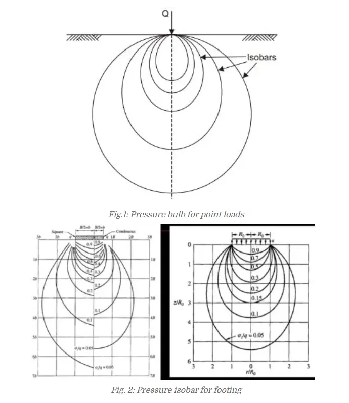
Pressure Bulb Theory -
An isobar or pressure bulb is a stress contour or a line which connects all points below the ground surface at which the vertical pressure is the same. In fact, an isobar is a spatial curved surface and resembles a bulb in shape; this is because the vertical pressure at all points in a horizontal plane at equal radial distances from the load is the same. Thus, the stress isobar is also called the ‘bulb of pressure’ or simply the ‘pressure bulb’. The vertical pressure at each point on the pressure bulb is the same. Pressure at points inside the bulb are greater than that at a point on the surface of the bulb; and pressures at points outside the bulb are smaller than that value. Any number of pressure bulbs may be drawn for any applied load, since each one corresponds to an arbitrarily chosen value of stress. A system of isobars indicates the decrease in stress intensity from the inner to the outer ones and reminds one of an ‘Onion bulb’. Hence the term ‘pressure bulb’.
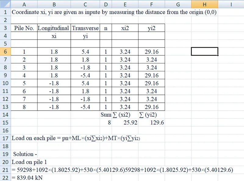
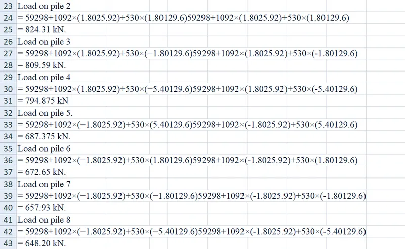
Que) To calculate the reaction exerted on the group of piles from the pier of the bridge.
Given Data -
- Total vertical reaction (P) = 5929 kN
- Total moment about L-L axis (ML) = 1092 kN.m
- A total moment about the T-T axis (MT) = 530 kN.m
- Total horizontal force along L-L axis (HL) = 83kN
- Total horizontal force along T-T axis (HT) = 172 kN
Assumption -
- Total no of piles (n) = 8 Nos.
- Dia of Pile = 1.2 M
- Distance between the p = 3.6 in both directions.
- Offset on both ends = 150 mm.