Week 5 Challenge
AIM- as per given data apply design wind load on the structure.
Given data-:
height of bridge is 9m
pier size 1.5*1.5m
loaction is mumbai open terrain obstruction ht less than 10m
calculation of wind pressure-:
step1:Wind Speed Vz=Vb*k1*k2*k3*k4
k1,k2,k3,k4 are taken from IS 875 part 3 tables and criteria of loacation and structure respectively as follows
basic wind speed Vb=47 m/s
k1=1.07(as str is important str), k2=1.00(as obstruction and ht is 9m), k3=1.00 (dgree is less than 3)
k4=1.30(post cyclone importance)
Vz=47*1.07*1*1*1.30=51.7987 m/s say 51.8m/sec
wind pressure Pz=0.6Vz^2=0.60*51.8*51.8=1609.944N/m^2 or say 1.61Kn/m^2(this load has to be applied on super structure)
STADD PRO ANALYSIS
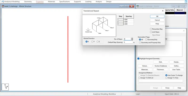
Create a node to structure a frame of 4 legged spaning 4m each pier size 1.5*1.5, ht 9m with fixed support and span of 10m
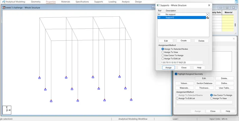
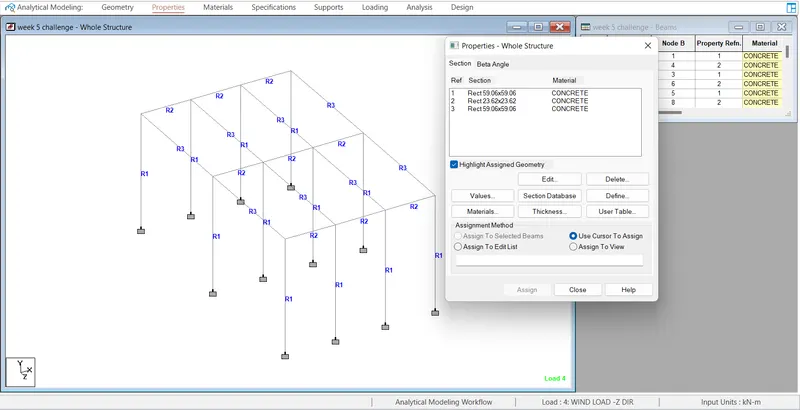
Next step after assing support then assing properties to the member as cross beam girder of rec(0.6*0.6m) and main girder of rec(1.5*1.5)
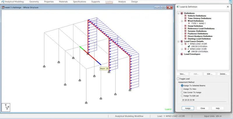
after assigning property to the member now define loading load as wind pressure is 1.61kn/m^2 and we provide it as udl mannually so for pier (1.5*1.5m)and main girder(1.5*1.5m) the along +X direction and -X direction W1=1.61*1.5=2.415kn/m apply this w1 and showing loading diagram
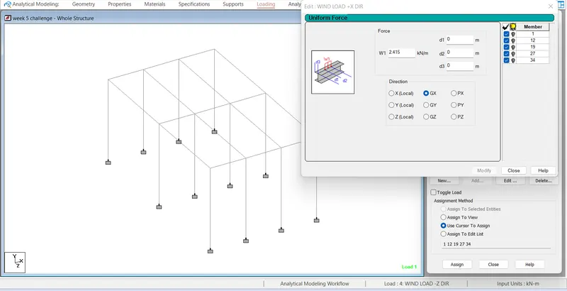
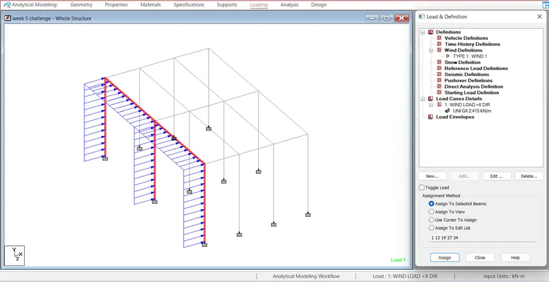
-X direction loading
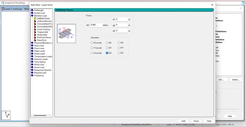
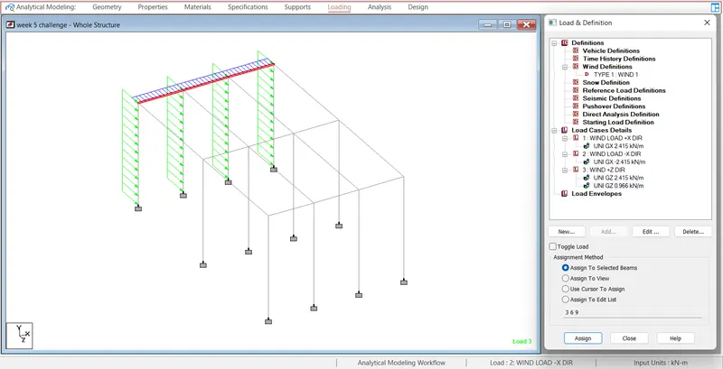
Simillarly in +Z direction and -Z direction the pier W1=-2.415kn/m but for cross beam girder(0.6*0.6m) W1=1.61*0.6=0.966kn/m this loading has to be apply by selecting the beam member
loading diagram of +z & -z dir
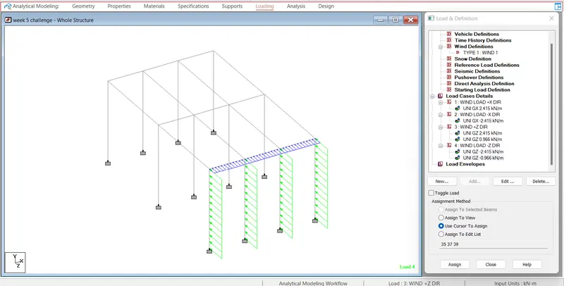
Next to perform analysis Run the analysis we get the deflection as shown in figure and report of maximum moment and shear as follows
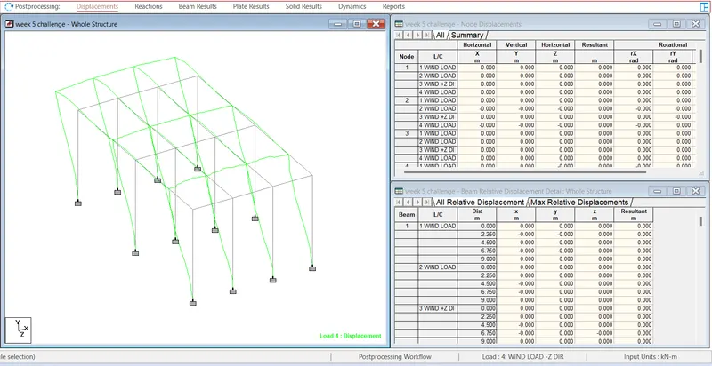
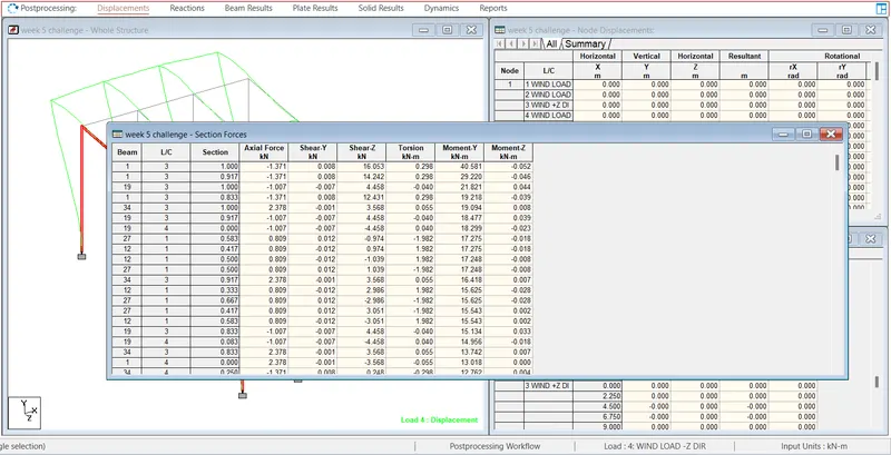
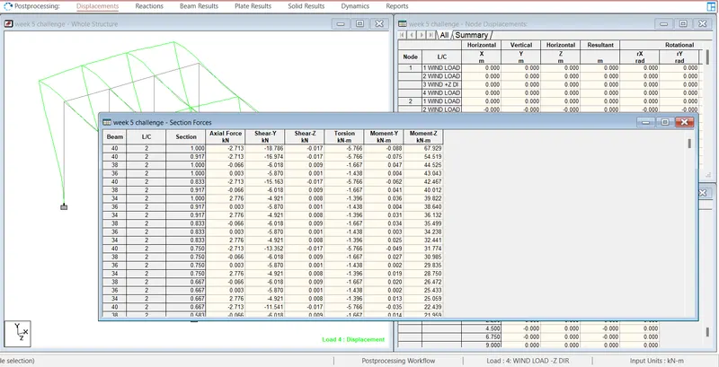
result summary
as we get the maximum shear @-z 16.053kn
maximum moment @-z -0.052
maximum moment @-Y 40.581
simillary rest result we can get by selecting member and click on report section force and get the required result