Week 10 Challenge
Aim: To determine the snow load acting on bridge and analyze accordingly in Staad.Pro.
Introduction:
The objective is to calculate snow loads from the given data manually and attempt the same in Staad.Pro for the bridge and analyse the results and effects on the structure.
The Illustrated bridge is 10.0 m long in length and width of 12.0 m having cantilever of 3.0m and parapet wall of height 1.5m.
Given Data (for calculation):
Span of bridge = 10.0 m
Width of carriage way = 12.0 m
Number of Main Girders = 4
Type of snow = Settled snow
Slope of deck = Flat (β <30 degree)
Depth of snow = 1250 mm
Assumption:
Size of Pier = 1.5 m Diameter
Height of Pier = 10.0 m
Size of Cross beam = 0.6 m x 0.9 m
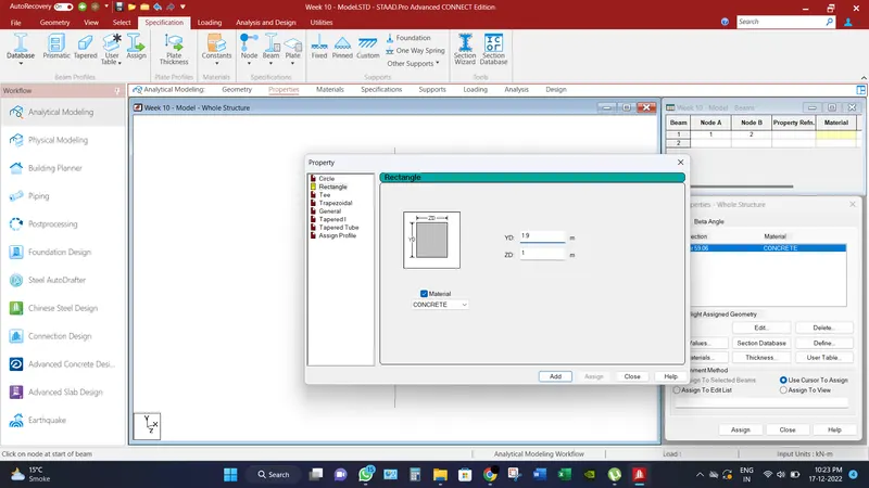
Size of main girder = 1.0 m x 1.9 m
Thickness of deck slab = 300 mm = 0.3 m
Thickness of parapet wall = 300 mm = 0.3 m
Procedure:
All the loads are calculated in such a manner as mentioned below,
For the calculation of Snow load,
Density of settled snow (ρ) = 300 Kg/m3
Depth of snow accumulation (D) = 1250 mm = 1.25 m
Slope of floor/roof (β) = 0
Snow Load, S0 = β x D x ρ = 3 x 1.25 x 10 = 37.5 KN/m
Shape Coefficient from IS 875 Part 4,
For angle β < 300, μ = 0.8
Design Snow Load,
S = μ x S0 = 0.8 x 37.5 = 30 KN/m
For the calculation of Self-weight of parapet wall,
Height of parapet wall = 1.5 m
Thickness of parapet wall = 300 mm = 0.3 m
Density of concrete (ρc) = 25 KN/m3
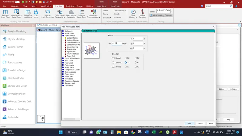
Self-weight load of Parapet wall = 1.5 x 0.3 x 25 = 11.25 KN/m
Computer Proficiency:
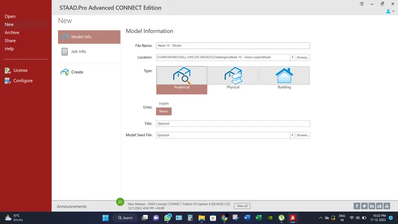
- Create a model by putting the necessary inputs as file location, units etc.
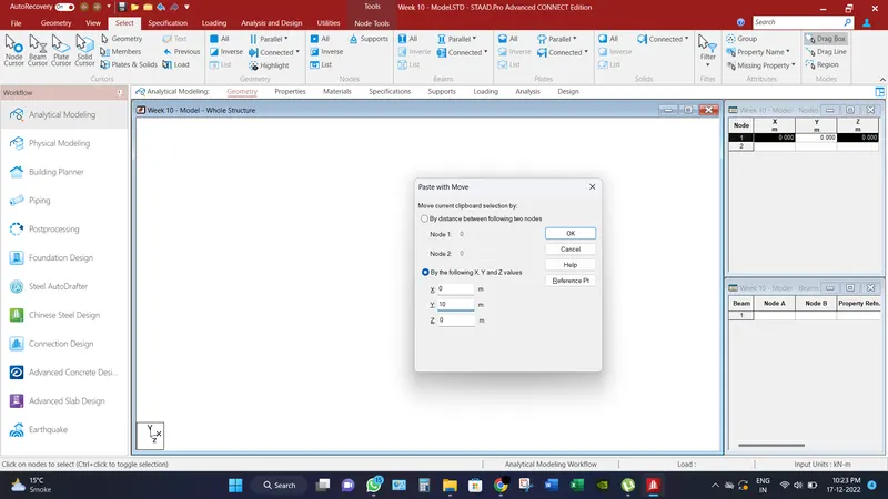
- Create two nodes (x,y,z) represents as (0,0,0) & (0,10,0) Because the height of pier is assumed to be 10 m.
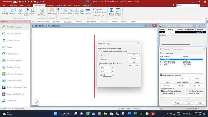
- Go to Add Beams option and connect the both nodes. And replicate the pier at spacing of 12.0 m in z direction.
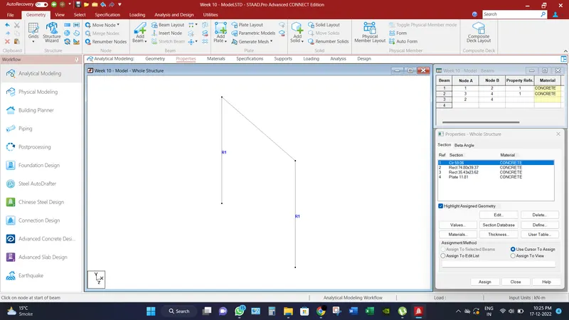
- Connect the beam at the top of pier by add beams option in order to make cross beam of carriageway.
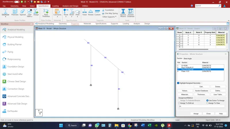
- Go to Properties tab, define the size of piers, cross beam & girder beam as mentioned above and assign all the members accordingly.
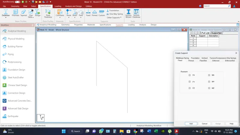
- Go to supports tab, and create fixed support and assign to end of peirs.
- Select the end nodes of cross beam and replicate the node at 3.0 m distance and connect the beams in order to make cantilever for parapet wall.
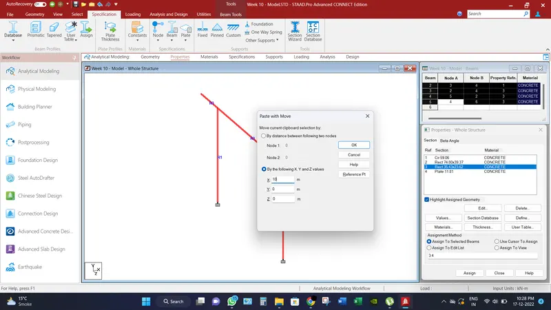
- Select the whole assembly and replicate it in 10.0m in x direction and connect top of the piers in order to make the beam girder.
- Assign all the missing property element as discussed above. Refer image below.
- Divide the outer cross beams into three parts by the insert node tool and replicate the cross beams at spacing of 4.0m. Refer image below.
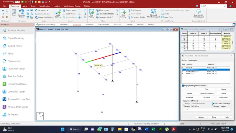
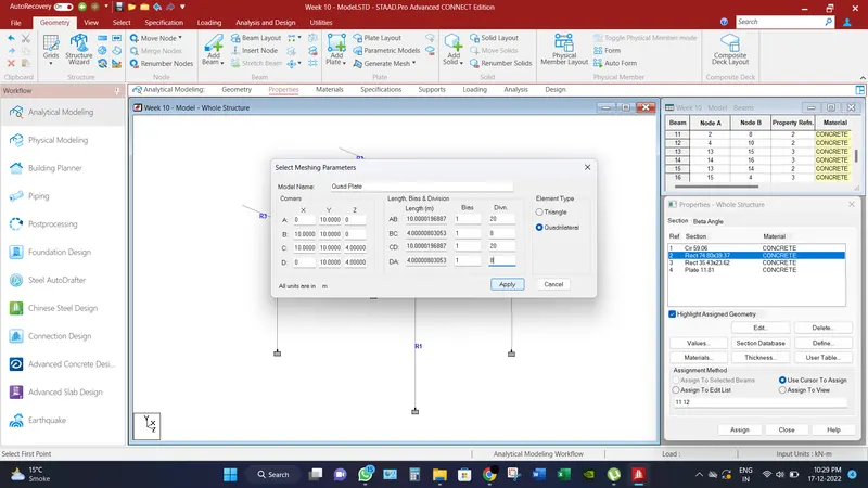
- Go to create mesh, and connect corner node of the panel and create quadrilateral mesh of 0.5 m x 0.5 m.
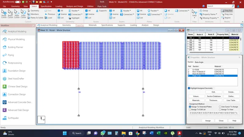
- Assign the thickness of the plate and replicate it into every panel in order to make deck slab.
- Go to loading tab, define the snow load as discussed above and assign to the cross beams of bridge. Refer image below.
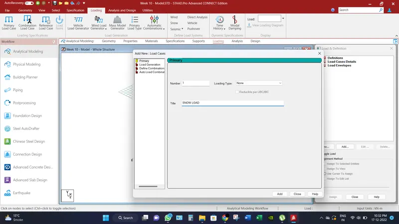
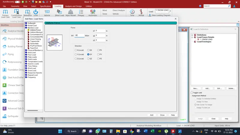
- Add another load case for minimum load of snow as per IRC which is 900 Kg/m2. And assign the load to the plates of deck slab. Refer image below.
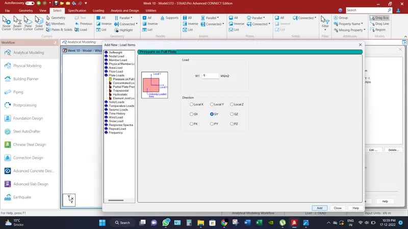
- Add Dead load case for Self-weight of structure and weight of parapet wall and assign the loads accordingly by the intensity as discussed above. Refer image below.
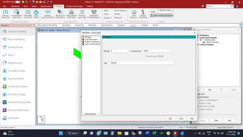
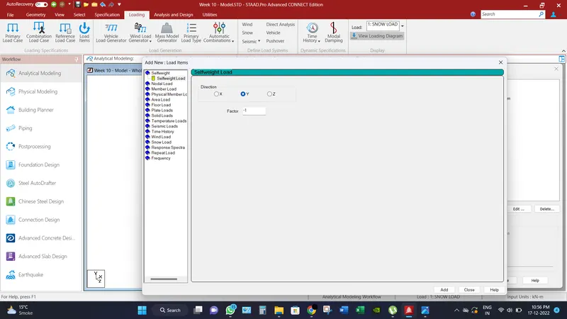
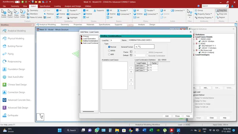
- Add a load combination of Dead and snow load with a serviceable factor as 1 for result purposes.
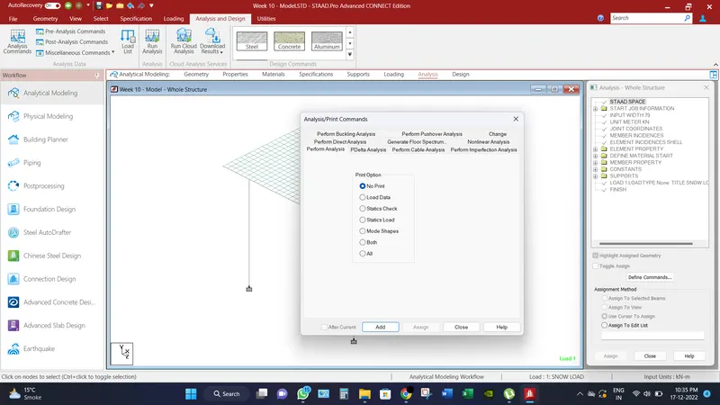
- Then Go to Analysis tab, select Analysis command and add the perform analysis command.
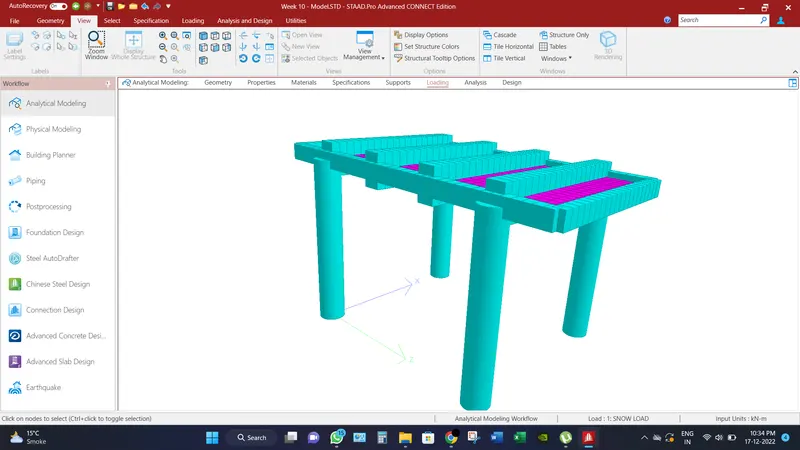
 18. 3D rendered view of the structure is illustrated below.
_________________________________________________________________________________
Analytical Results:
Bridge has been analyzed and check for different load combination and different displacement for different scenarios has been record.
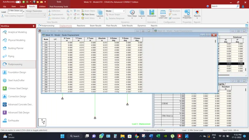
Maximum node displacements is recorded as 13 mm.
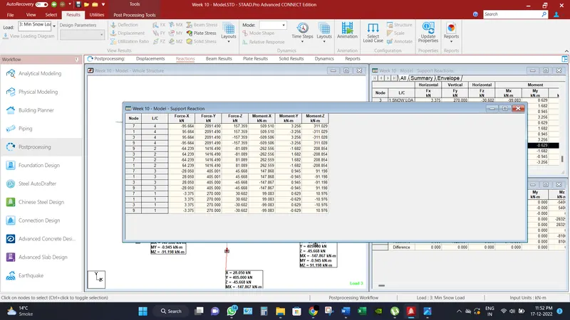
Maximum Base reactions are recorded axial force as 2091.49 KN and moment as 509.51 KN-m.
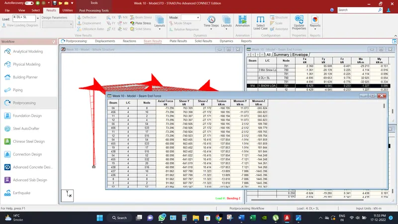
Maximum shear force recorded in beam in Fy direction is 763.309 KN.
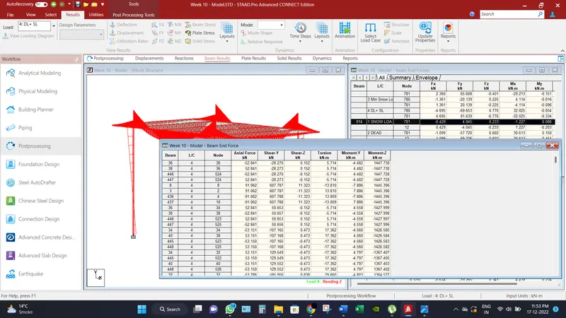
Maximum Bending Moment recorded in beam in Mz direction is 1447.73 KN-m.
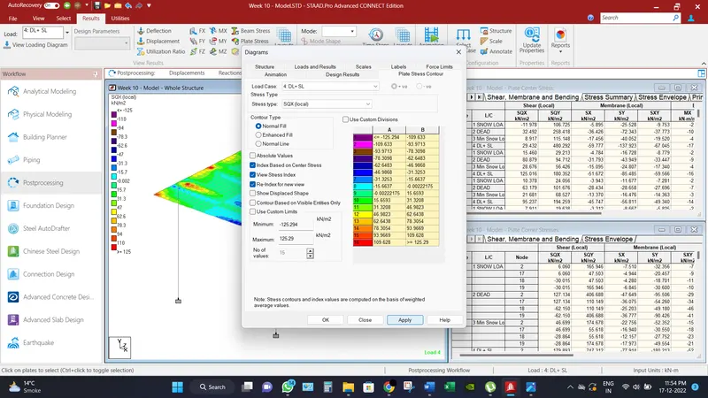
Maximum Shear Force in SQX (local) direction for deck slab is recorded as 125.29 KN/m2.
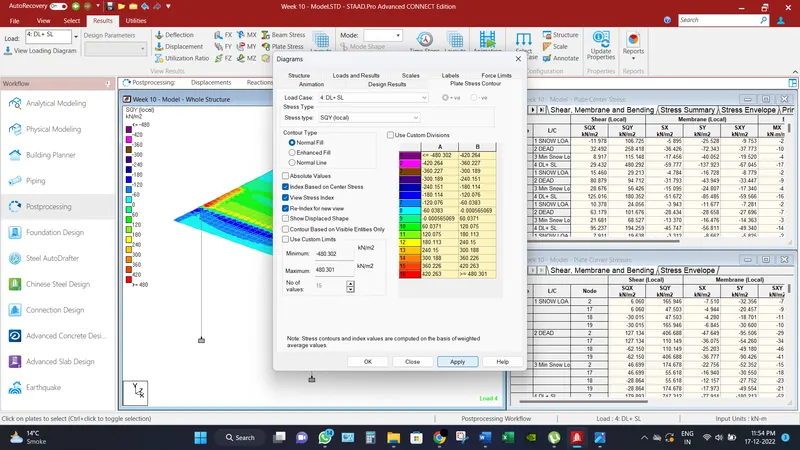
Maximum Shear Force in SQY (local) direction for deck slab is recorded as 480.301 KN/m2.
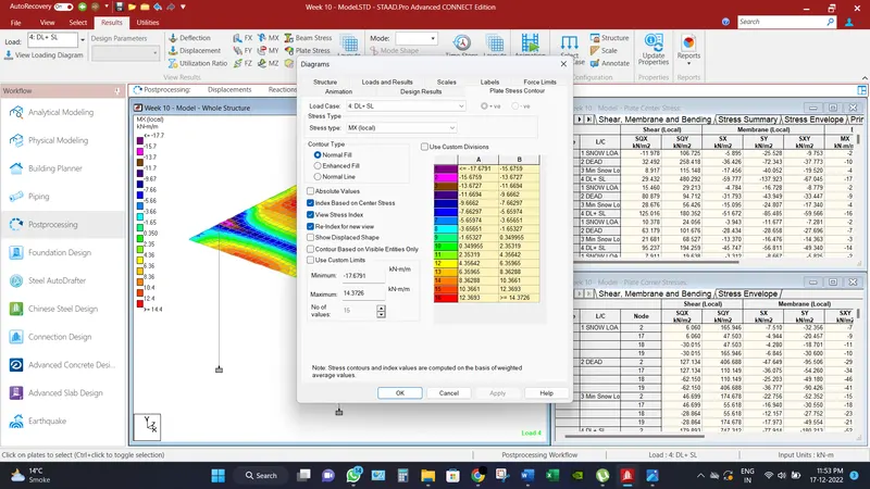
Maximum Moment in MX (local) direction for deck slab is recorded as 14.373 KN-m/m.
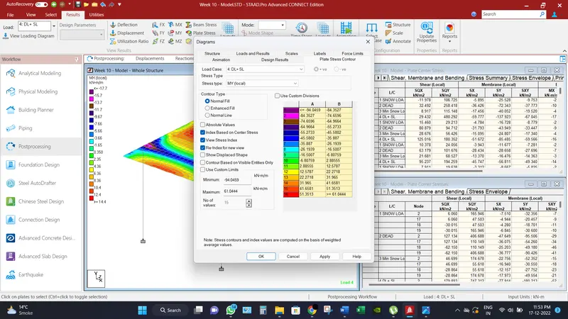
Maximum Moment in MY (local) direction for deck slab is recorded as 61.044 KN-m/m.
_________________________________________________________________________________
Conclusion:
Different results have been found under the snow loads,
Maximum node displacements is recorded as 13 mm.
Maximum Base reactions are recorded axial force as 2091.49 KN and moment as 509.51 KN-m.
Maximum shear force recorded in beam in Fy direction is 763.309 KN.
Maximum Bending Moment recorded in beam in Mz direction is 1447.73 KN-m.
Maximum Shear Force in SQX (local) direction for deck slab is recorded as 125.29 KN/m2.
Maximum Shear Force in SQY (local) direction for deck slab is recorded as 480.301 KN/m2.
Maximum Moment in MX (local) direction for deck slab is recorded as 14.373 KN-m/m.
Maximum Moment in MY (local) direction for deck slab is recorded as 61.044 KN-m/m.