Wiring harness design in CATIA V5 - 3D modeling Week 4 Challenge
Project On wiring harness design in CATIA V5 - 3D modeling
Q1. Route the following harness layout in the Electrical workbench. Make assumptions for harness bundle diameters. Use the Following connectors as shown in the layout diagram.
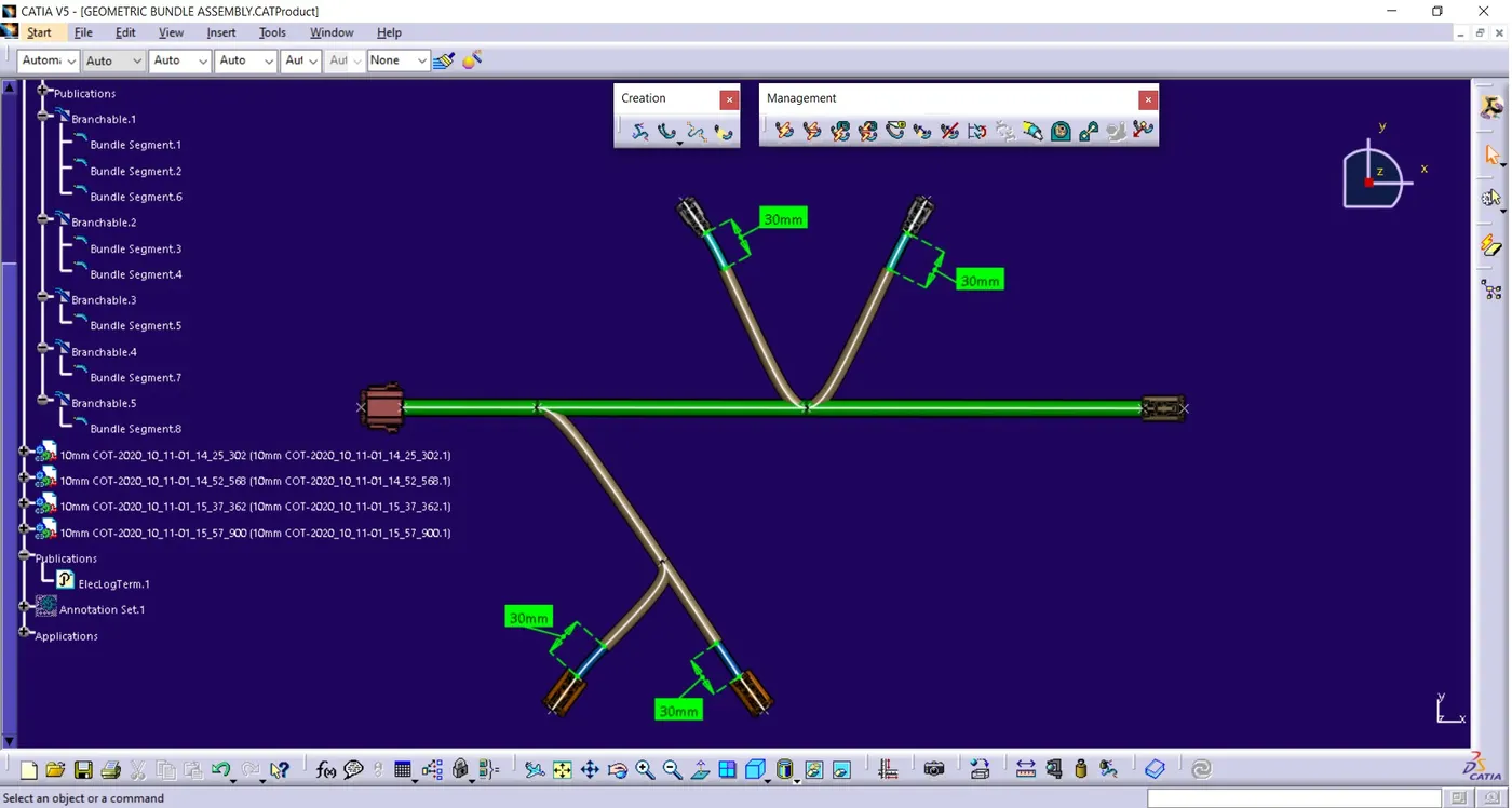
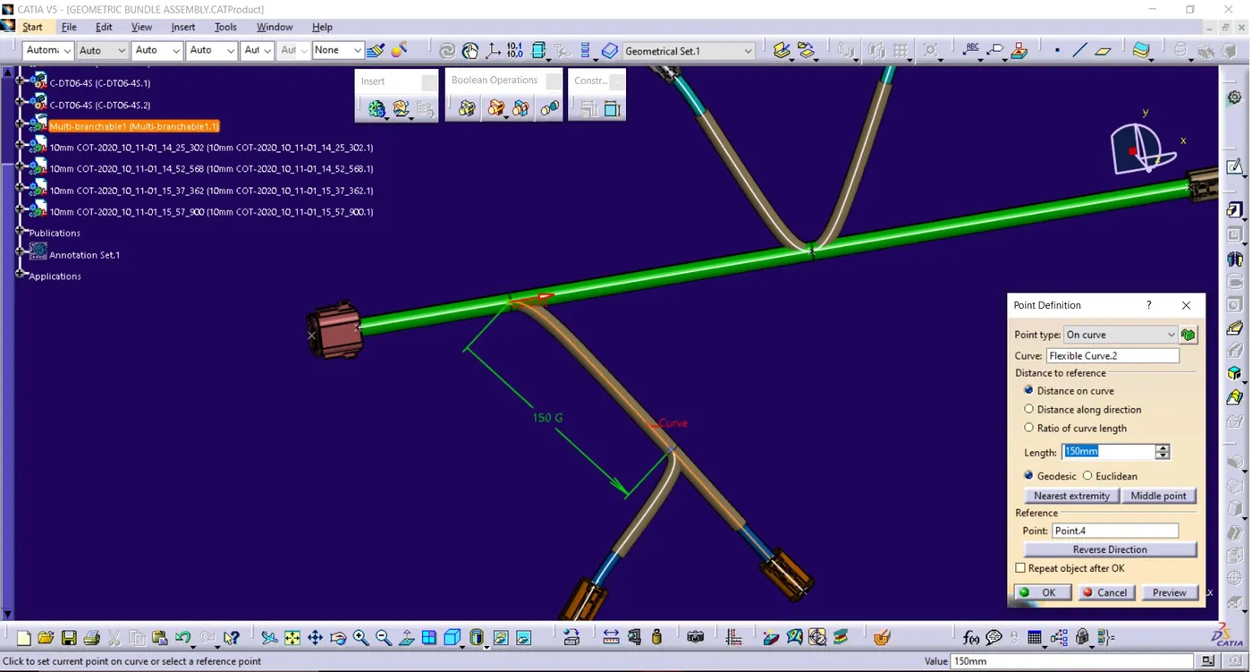
Add protective covering on all branches connected to DT06-2S & DT06-4S connectors. Keep end extremity at 30mm (from connectors end)
Download connector 3D data from www.te.com
- DT06-4S
- DT06-6S
- DT06-2S
- DT06-8S
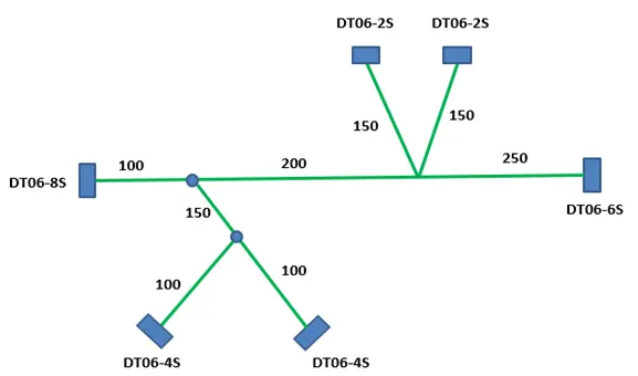
Ans)
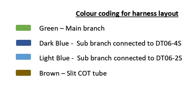
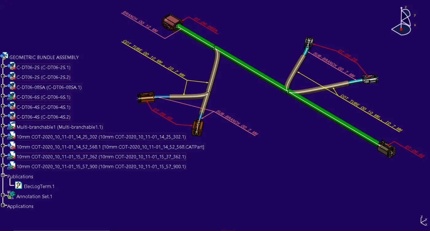
- HARNESS LAYOUT:-
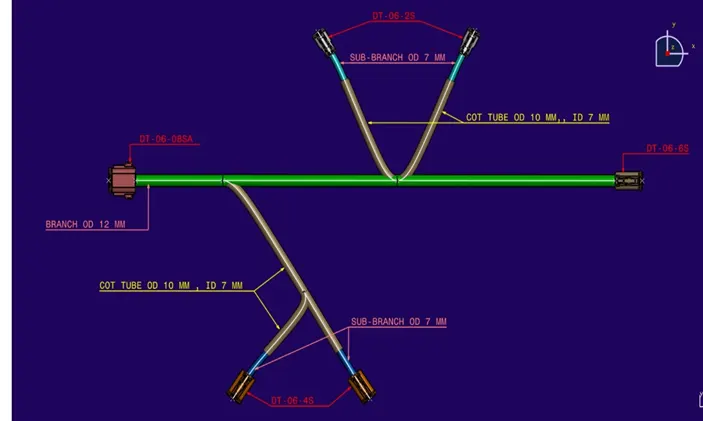
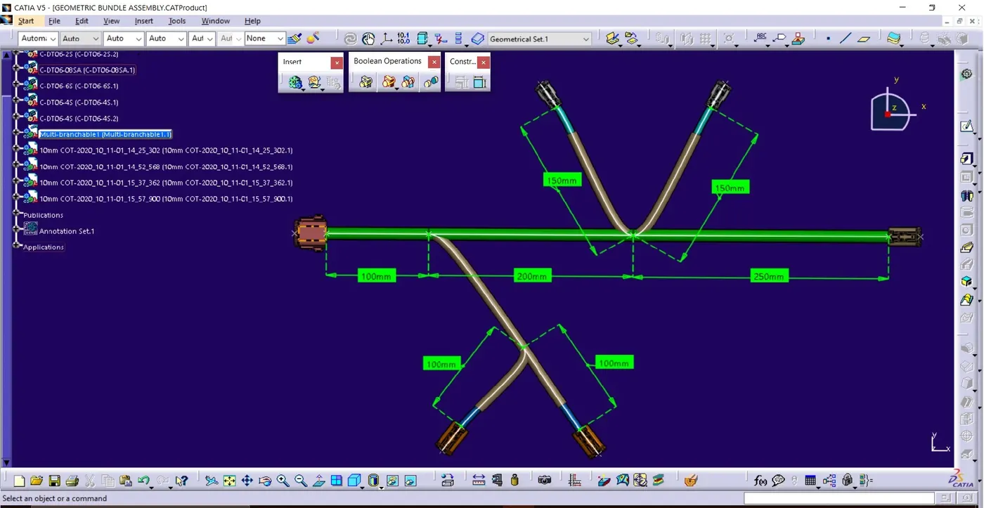
- HARNESS LAYOUT BRANCH POINT DIMENSIONING:-
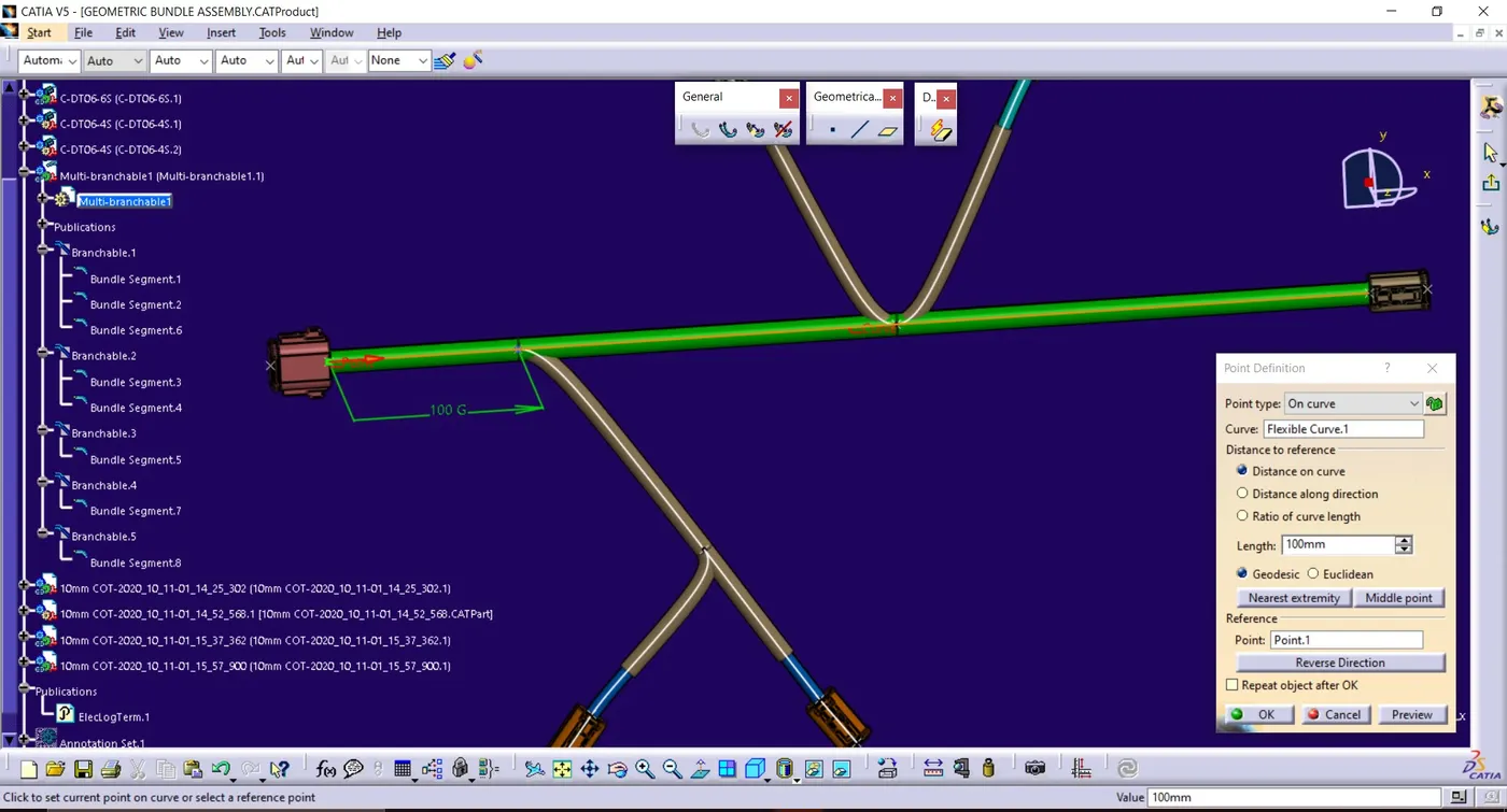
- BRANCH POINT 1:-
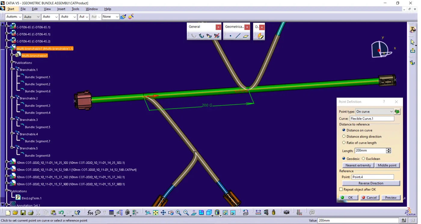
- BRANCH POINT 2:-
- BRANCH POINT 3:-
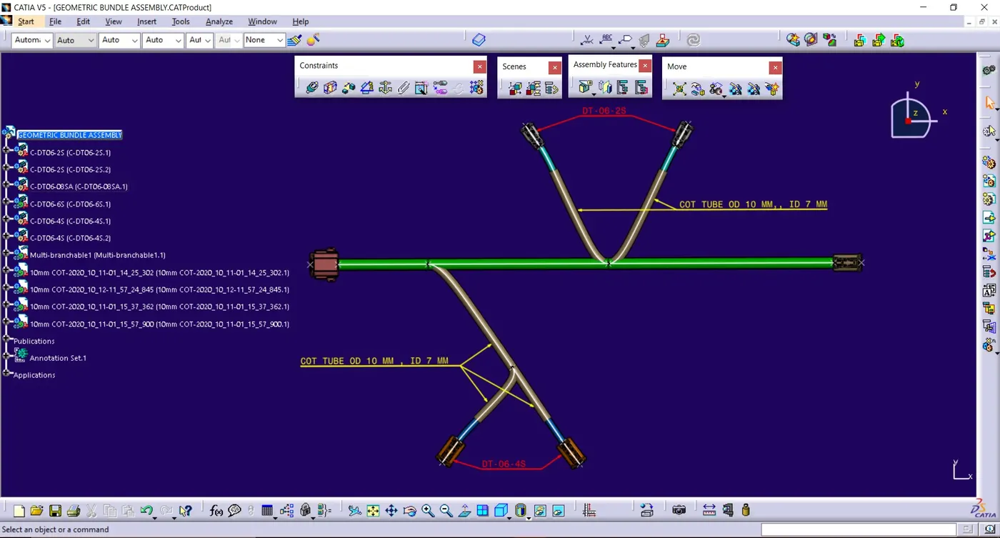
- Protective covering added on all branches connected to DT06-2S & DT06-4S connectors. Keep end extremity at 30mm (from connectors end)
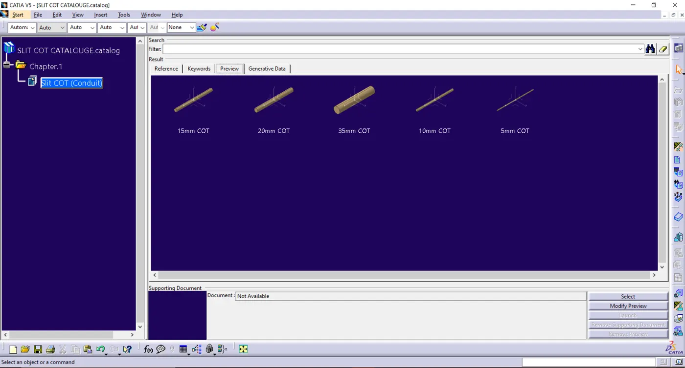
- PROTECTIVE COVERING COT TUBE “10mm COT” IS ADDED ON BRANCHES CONNECTED TO DT06-2S & DT06-4S, COT TUBE IS USED FROM CATALOG CREATED IN THE PREVIOUS PROJECT:-
- CATALOG OF PROTECTIVE COVERING “COT TUBE”
- END EXTREMITY OF 30 mm IS KEPT FROM CONNECTOR END AS SHOWN IN FIG.