Week 10 - Challenge 1- Attachment Feature Creation (Ribs & Screw Boss)
Objective:
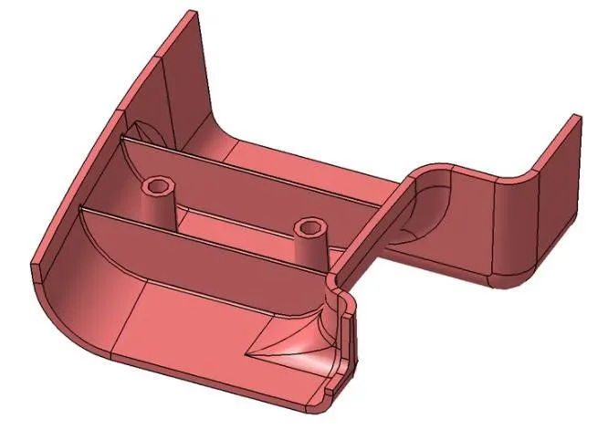
- To create ribs for the drill handle considering the design rules as per the video.
- To create screw bosses for the drill handle considering the design rules as per the video.
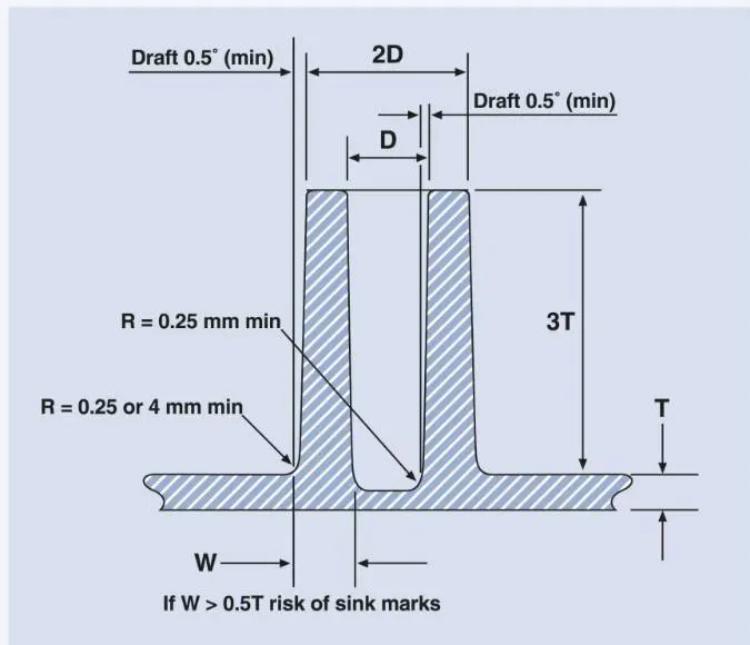
General Guidelines for Bosses:
- Draft - 0.5 degrees on the walls of boss
- Thickness - Typically 40%* of the nominal wall at the base.
- Height to Diameter Ratio - 3:1
- Radii - 0.25mm maximum radii.
REPORT
Ribs and screw bosses creation:
Tooling Axis:
Tooling axis is the direction along which the mold is actuated in order to perform a feasible injection molding to form the plastic component. The given class A surface is analyzed and the tooling axis is created.
Draft Analysis:
Draft angle is the taper provided for the molded or cast part perpendicular to the parting line. Draft angle is provided in degrees with 3 degrees being the nominal value. The component for injection molding should have drafts at both the core and the cavity side of the mold to ensure damage reduction and easier ejection. The draft also helps in reducing the vacuum forces by letting in air for the ejection. It also helps in giving a superior finish to the component.
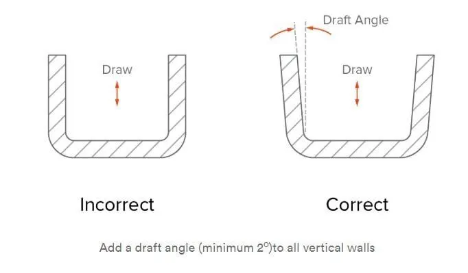
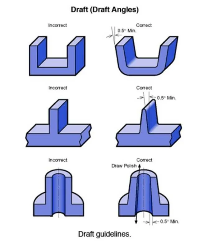
The draft should be a part of the design. The product design should take all of it into design consideration.
Nominal Draft Angle:
- Nominal draft angle should be 3 degrees.
- 7 degrees for textured surfaces.
- A minimum of up to 0.5 degrees can be produced at an increased production cost.
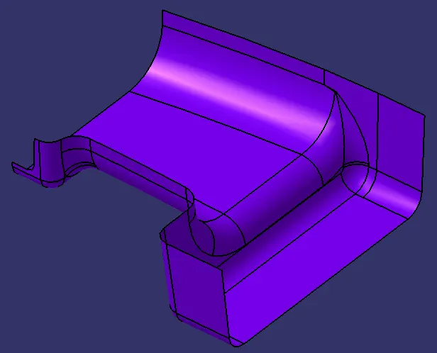
Class A Surface:
Given class A surface
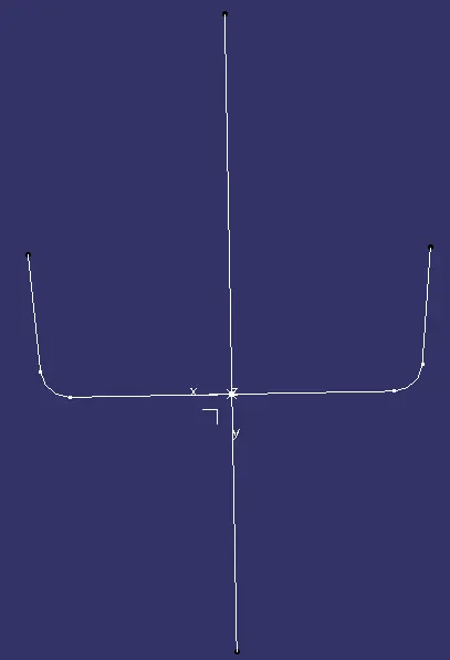
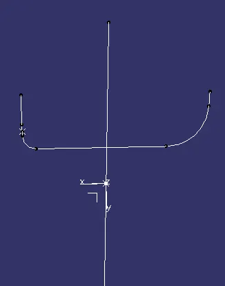
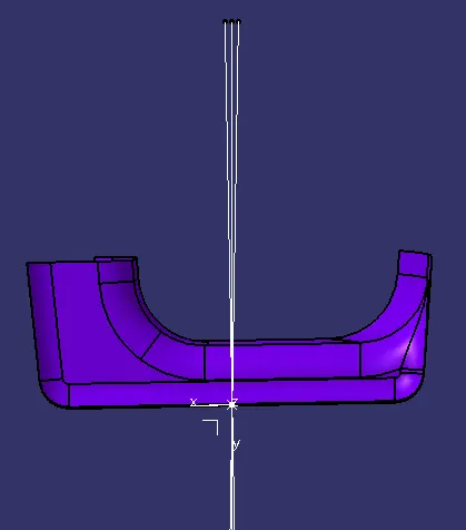
Tooling Axis Creation:
The tooling axis for this surface can be created by taking two of the directional line drawn perpendicular to the flat surfaces. Then those two lines are bisected in order to form the tooling axis.
Draft Analysis of Class A Surface:
A draft analysis is performed on the class A surface to check the feasible draft angle along the model. By using the analysis under the running point we can check draft angle on the individual faces. It shows how much draft on specific points when we move the cursor point.
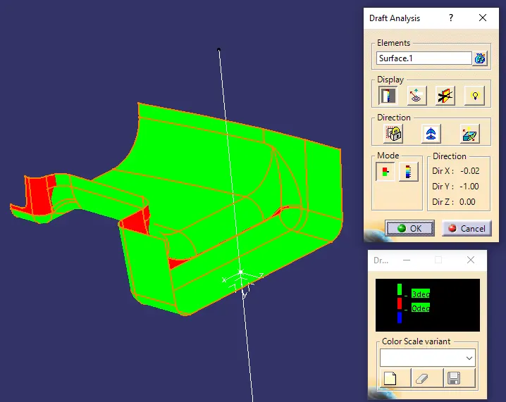
Green colour indicates values above 3 degree positive draft
Red colour indicates values between 3 and 0
orange colour indicates values below 0 degree
Use the compass function to align the compass to the tooling direction and lock the direction using lock function in the draft analysis tool bar. The surface is showing green colour and red colour so that the surface clears the minimum draft angle of 3 degree.
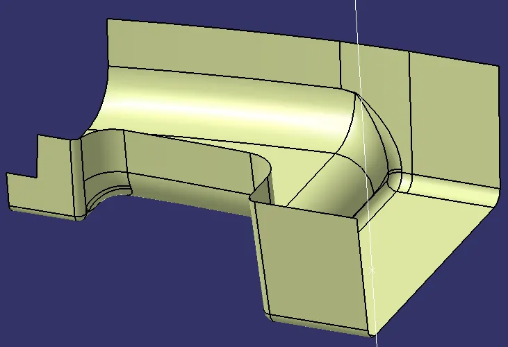
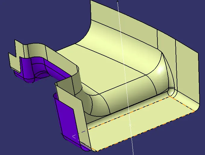
Class B Surface:
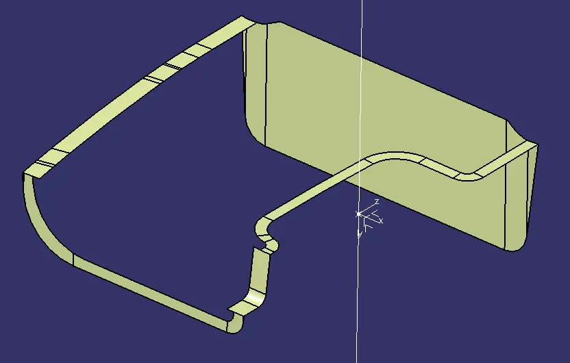
Class C Surface:
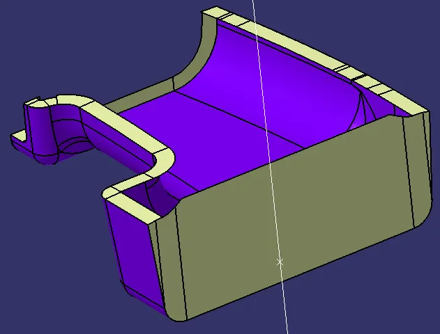
Class A and Class C joint surface:
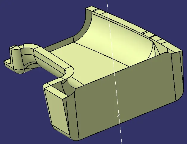
Trimmed Surfaces:
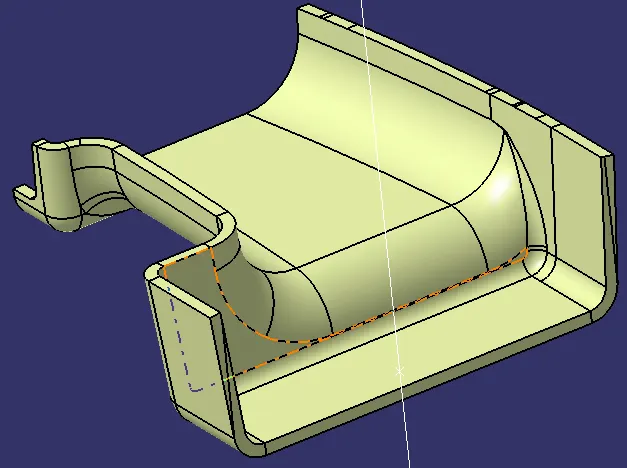
Closed Body:
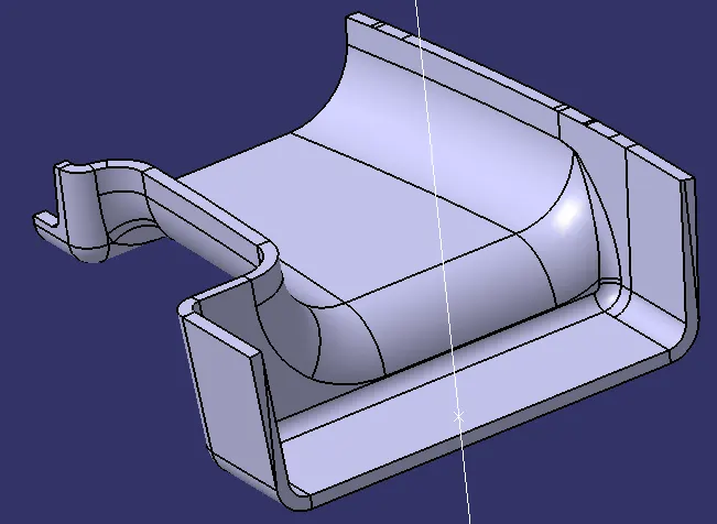
Simple tree structure:
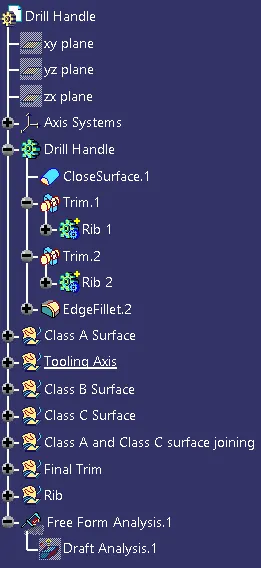
Rib Creation:
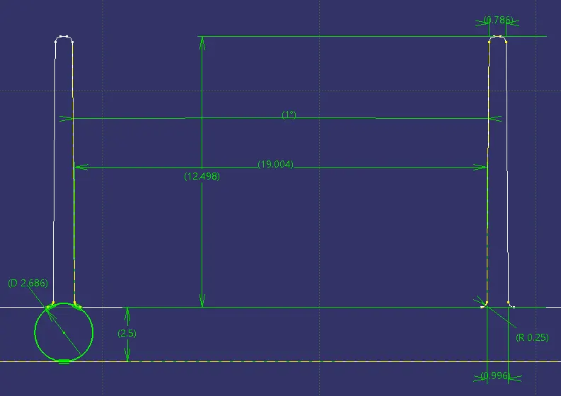
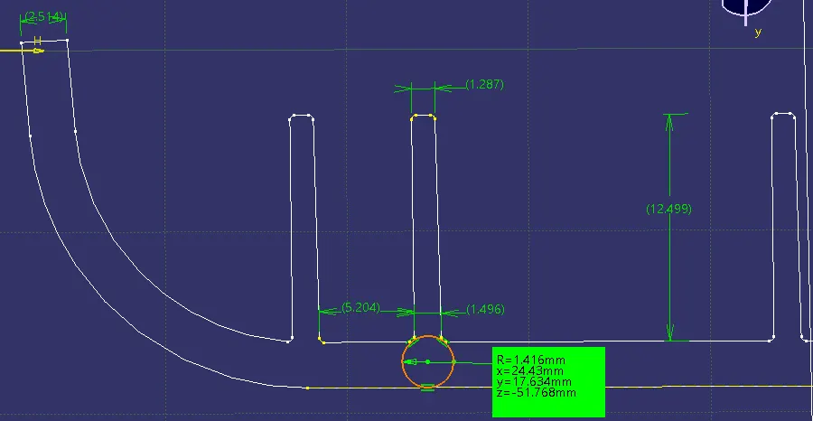
Design evaluation as per standards :
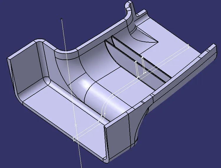
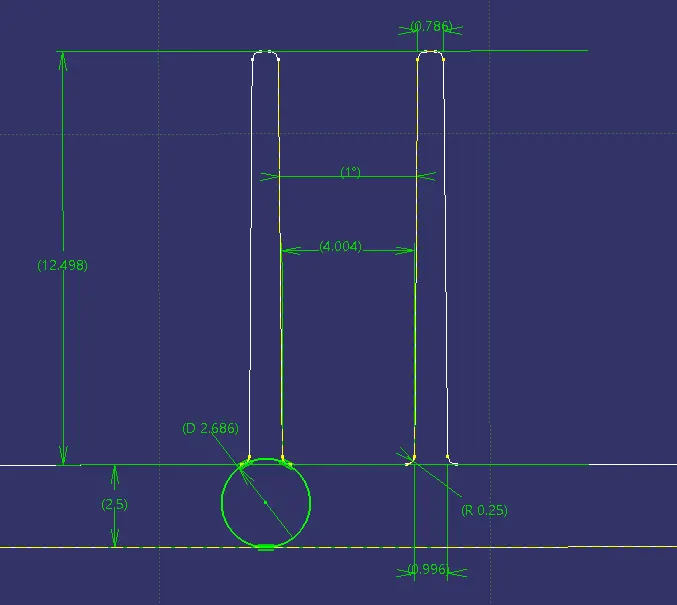
All are as per design standards mentioned , but Since its a customized Door handle and follows different HEIGHT TO DEPTH RATIO FOR THE SPACING BETWEEN THEM.
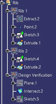
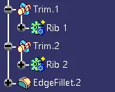
Rib Design Tree Structure:
Screw Boss Creation:
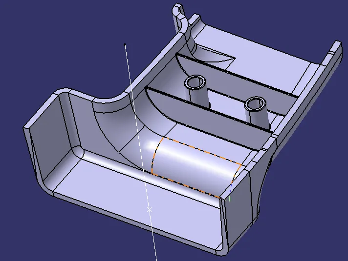
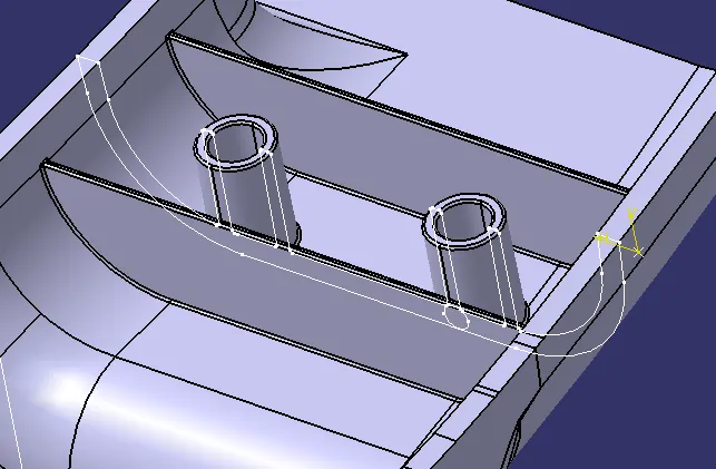
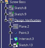
Design Verification:
Screw Boss Tree:
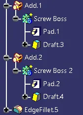
Draft Analysis:
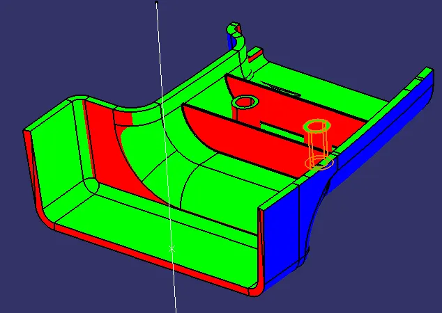
Draft analysis is done using featured draft analysis tool
Use the compass function to align the compass to the tooling direction and lock the direction using lock function in the draft analysis tool bar.
the surface is showing green colour and red colour so that the surface clears the minimum draft angle of 3 degree and 0.5 deg on RIBS and SCREW BOSSES
By using the analyses under the running point we can check draft angle on the individual faces. It shows how much draft on specific points when we move the cursor point.
Green colour - above 3 degree positive draft
Red colour -between 3 and 0
blue colour- below 0 degree
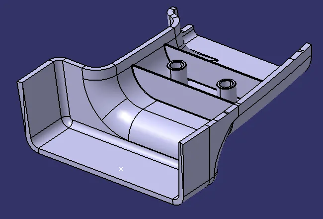
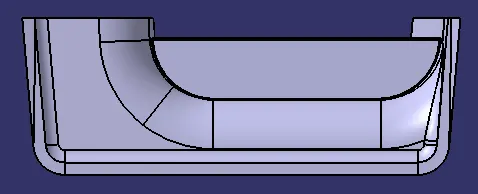
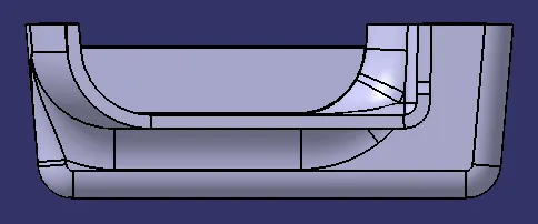
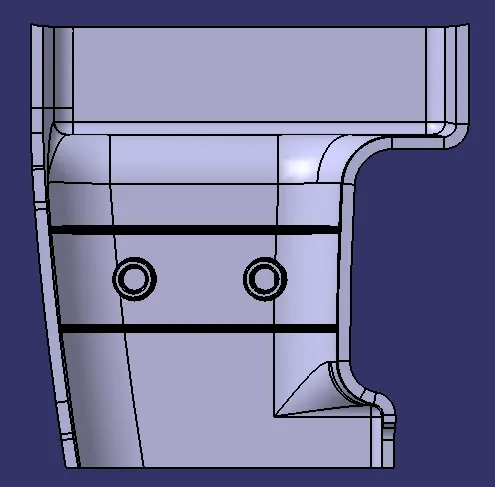
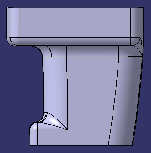
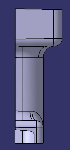
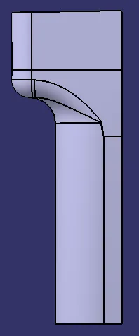
Different Views:
Conclusion:
- Created the DOOR HANDLE component using the given Class-A surface.
- The tooling axis for the given Class-A Surface is created which meeting the requirements of the draft angle.
- Draft analysis is done on the CLASS-A surface.
- Class-B and Class-C surface is created.
- Using the Close Surface feature, Solid body is created from the surface.
- RIBS and SCREW BOSSES are designed as per design considerations.
- Draft analysis is done on the Final Component.