Week 10 - Challenge 1- Attachment Feature Creation (Ribs & Screw Boss)
Aim: - To create a DOOR HANDAL Plastic Component through a given Class A Surface and perform Draft
Analysis on the final plastic component.
Objectives:
- Creation of Tooling Axis.
- Creation of Class B and Class C surface.
- Creating a solid part out of surface modelling.
- Creating Screw Boss & Ribs on the component.
- Draft Analysis of Class A surface and final plastic component.
Provided Class A surface for component is shown below:
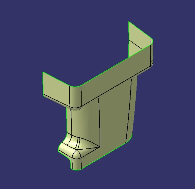
Identifying Tooling Axis
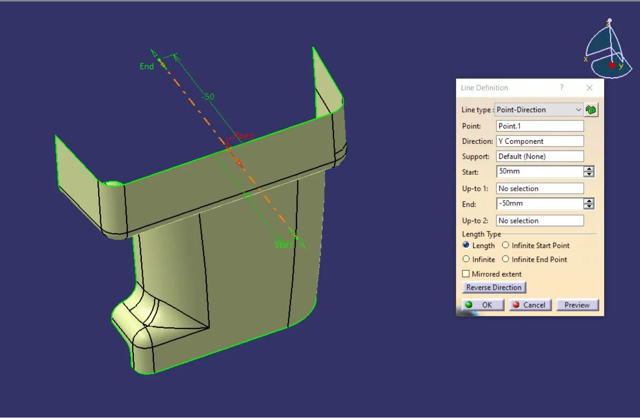
· On inspecting the part, the Y-Axis is the best option for tooling the component.
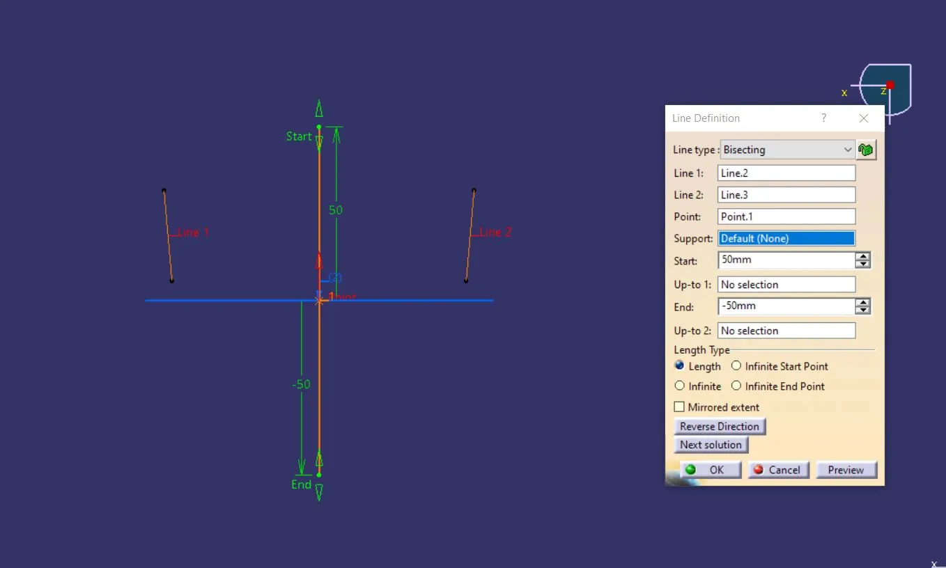
· As shown in image the part is divided using plane at the centre, using this as reference the tooling axis is created using bisecting line command.
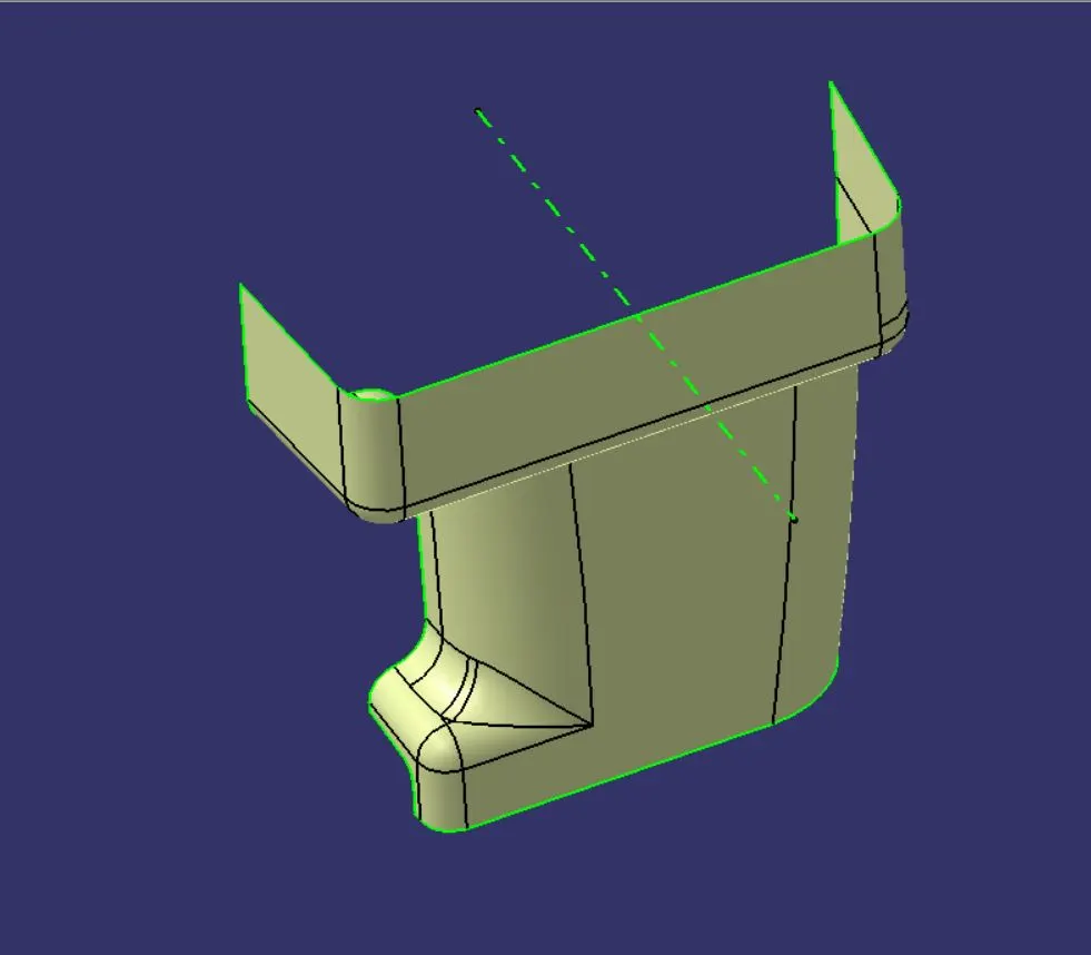
Creating Surface B
· Using extrapolate and off-set command the surface B is created which is shown in below image of off-set value of 2.5mm.
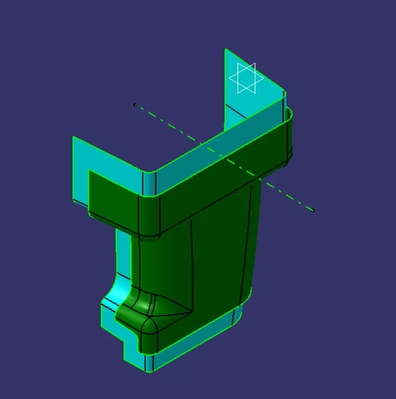
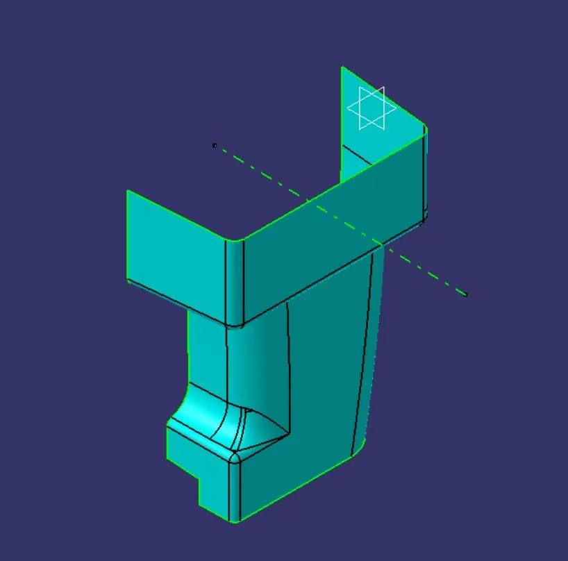
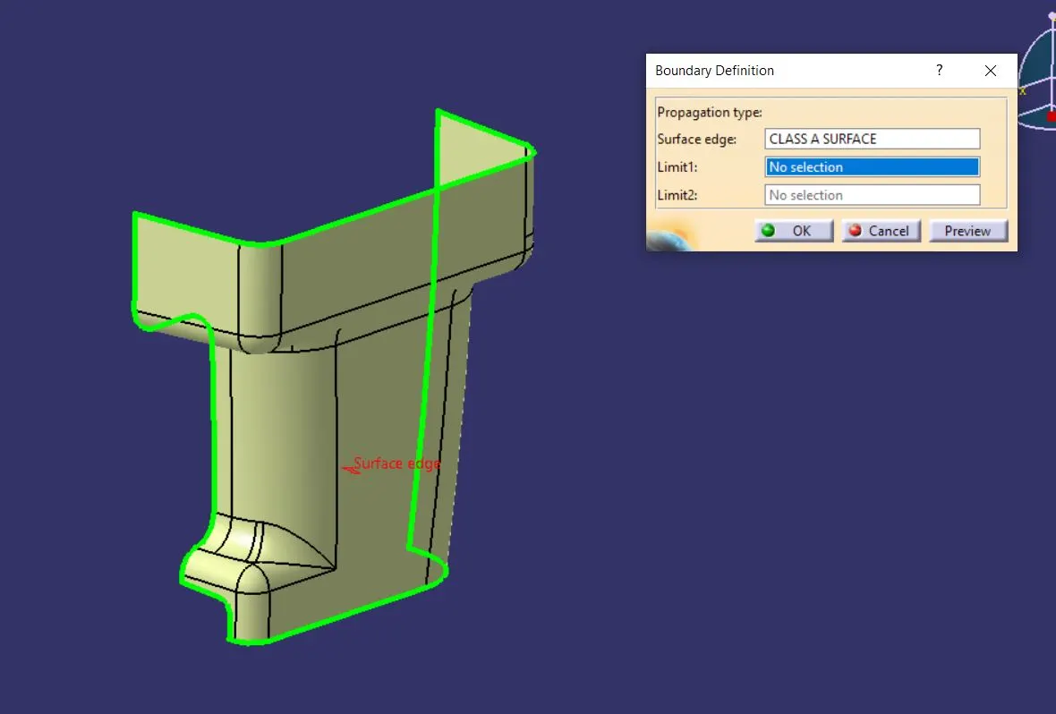
Creating Surface C
· Using Boundary command, the Class C surface is created as shown below:
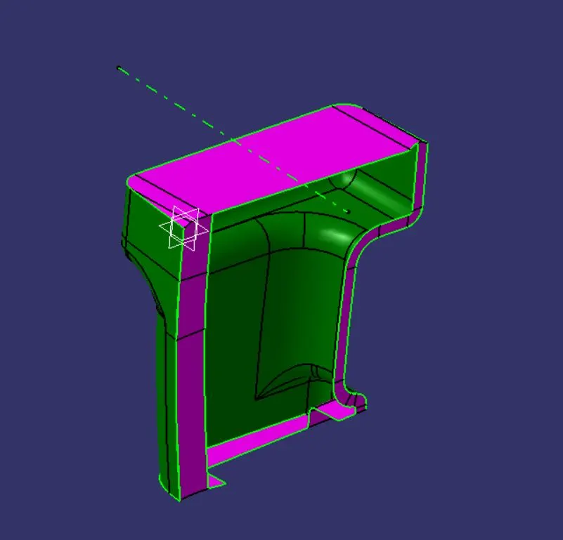
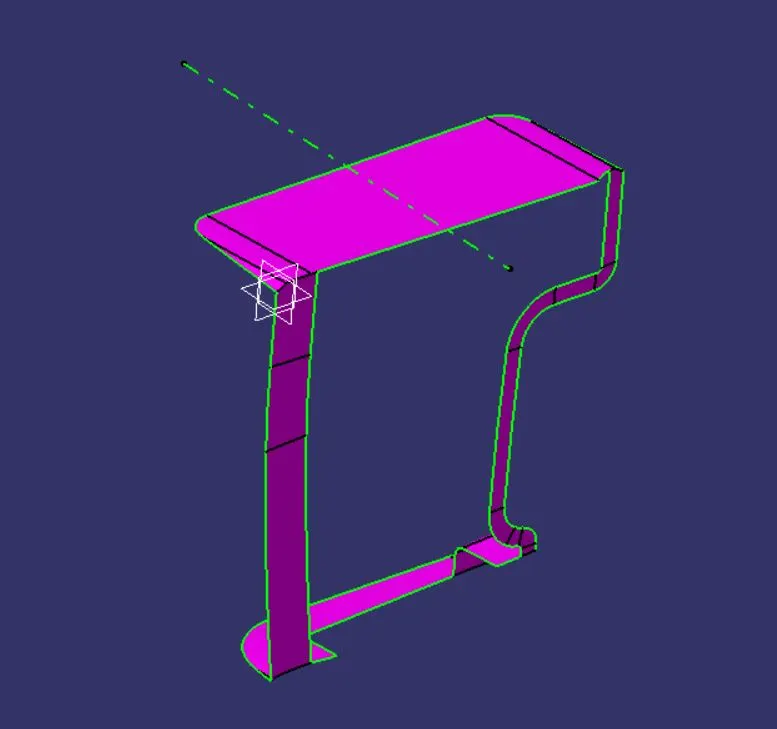
Final Tooling Surface
· Now using Trim command all the excess surfaces are trimmed and required final surface is formed as shown below:
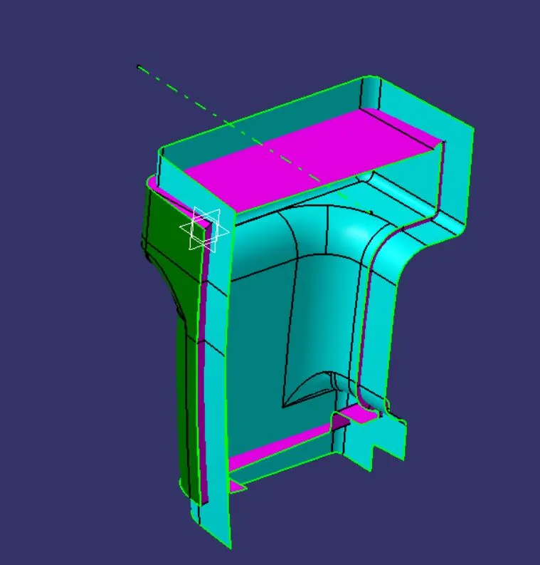
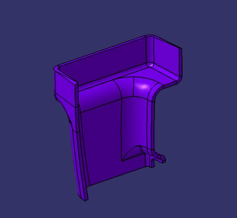
Converting to Solid Body
· After completing the Final surface, shift to Part Modelling interface, now using Closed Surface Command the whole Surface body is now converted into solid Plastic Component.
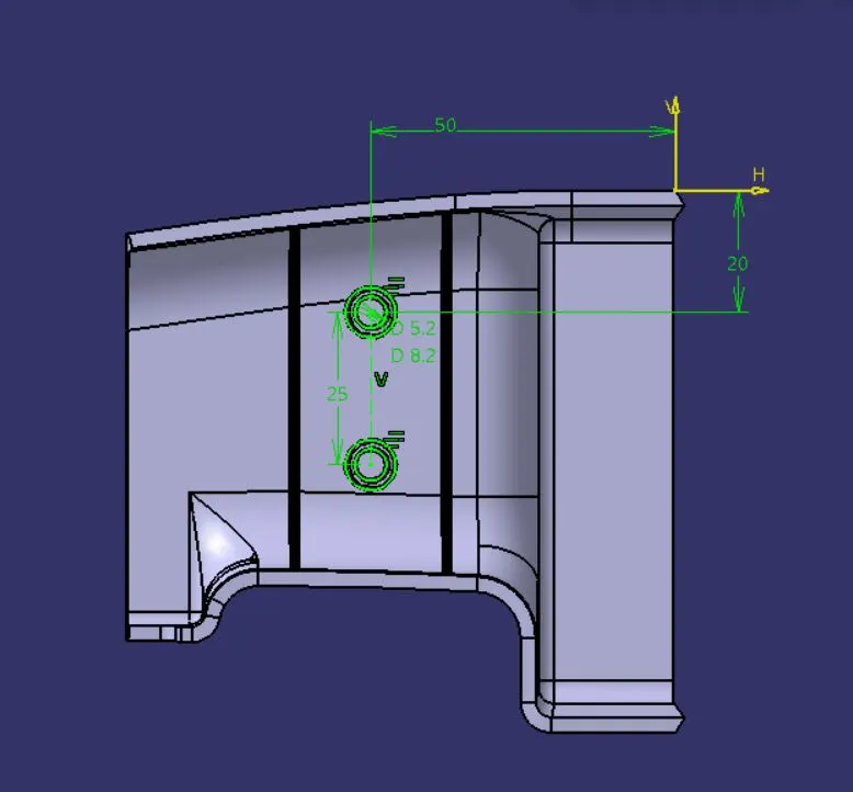
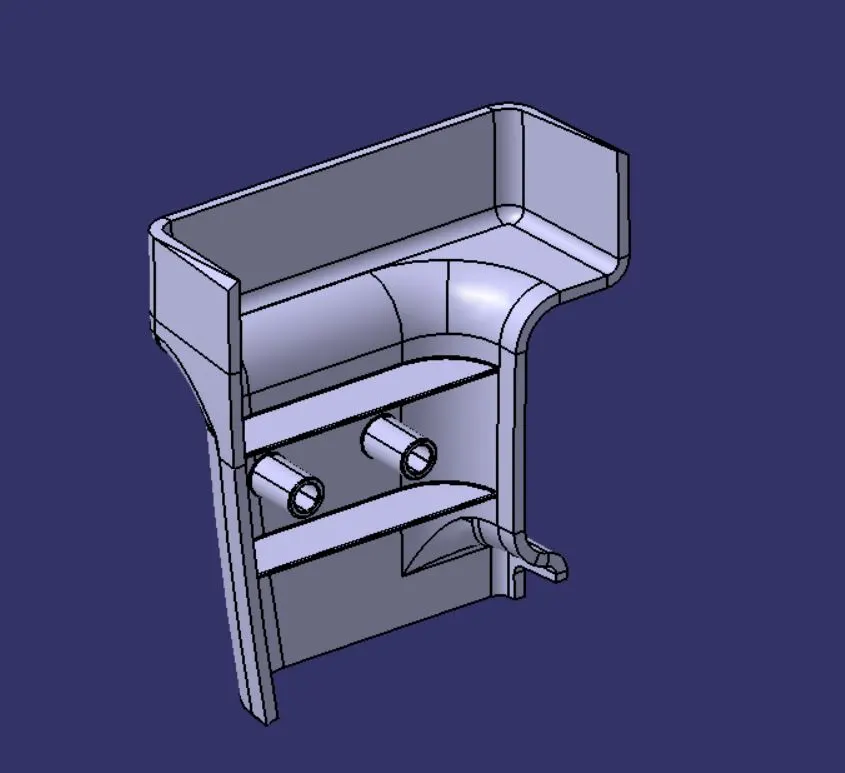
· Now adding the required Ribs & Screw Boss as per the question.
· As there is no mention of dimension of the ribs & screw Boss I have assumed the location as per provided picture.
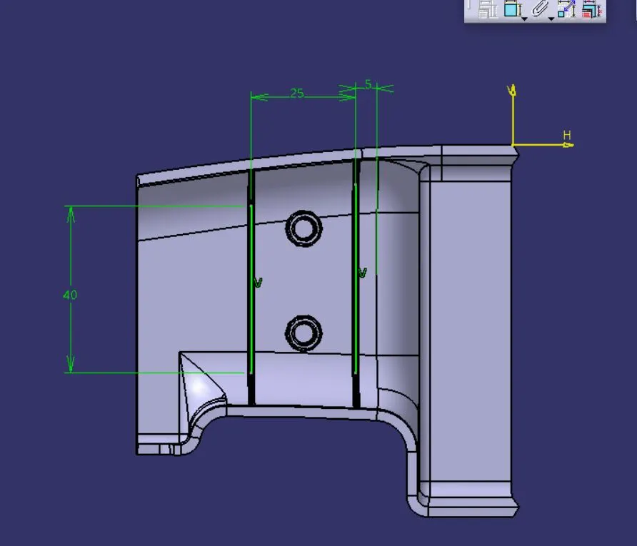
Draft Analysis on Final component
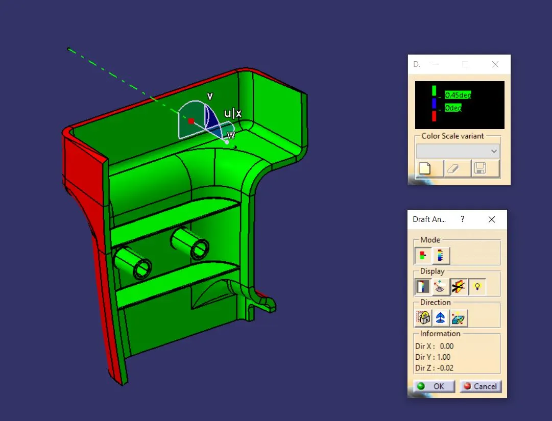
· As shown below the Draft angle is under well acceptable range for the Final part i.e. 0.45° for the Ribs & Screw Boss.
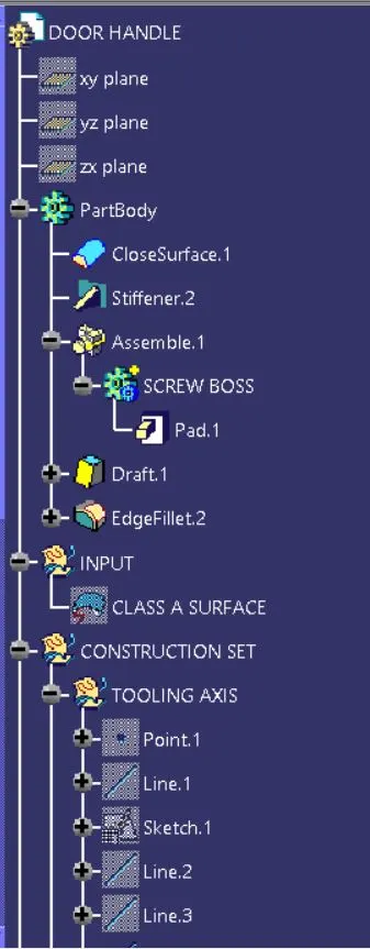
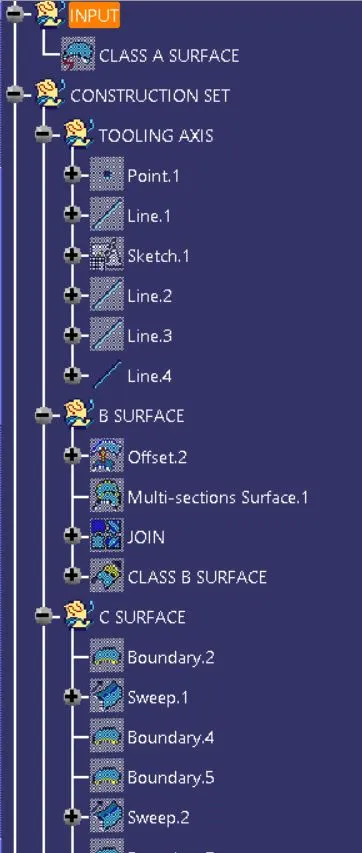
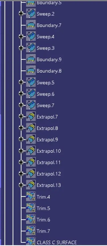
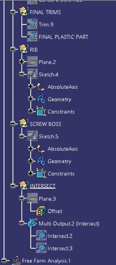
Following are the images of the Tree Structure of the Plastic Component: