Week 10 - Challenge 1- Attachment Feature Creation (Ribs & Screw Boss)
Aim:- 1. Create the rib for the Drill Handle considering the design rules mentioned in the video.
2. Create the Screw boss for the Drill Handle considering the design rules mentioned in the video.
Introduction:-
Rib-
Ribs are thin protrusions that extend perpendicular to a wall or plane to provide added stiffness and strength.
General Guidelines for Ribs:
Rib thickness- Ribs should be designed to be 50-60 percent of the nominal wall thickness. Thinner does not provide much structure and may be hard to fill. Thicker ribs are tempting, but they can begin to introduce sinks on the cosmetic surface.
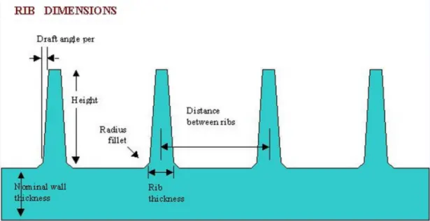
Rib height- Rib height should be no more than three times the nominal wall thickness for maximum effectiveness. Since the rib will be thinner than the wall, it may be hard to fill it if it is taller.
Rib spacing- Increase the number of ribs rather than their height in order to increase stiffness. Ribs should be spaced a minimum of two times the nominal wall thickness apart from one another.
Rib draft- A minimum 0.5 degree draft will ensure that they release from the tool during molding.
Rib coring- Core thick ribs from the back or below to create a blank area and thinner rib walls. This will help mitigate cosmetic sinks.
Rib radii- Radii at feature intersections should be a minimum of 0.5 - 1.0x nominal wall thickness to increase rib strength.
Screew Boss-
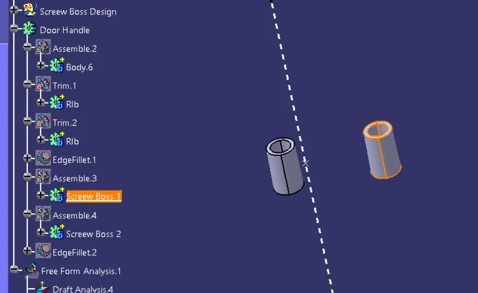
Screw bosses play a crucial role in molded parts as an attachment and assembly point. They are cylindrical protrusions that are typically located on a part's wall and contribute to various functions such as positioning aids, fixation points, facilitating gear rotation, and acting as bearing surfaces or levers.
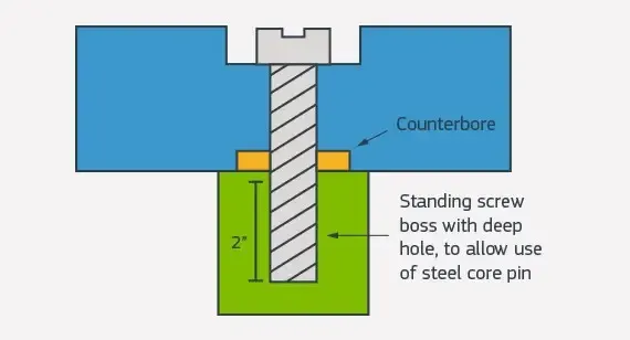
General Guidelines for Bosses:
- Draft - 0.5 degrees on the walls of the boss
- Thickness - Typically 40%* of the nominal wall at the base.
- Height to Diameter Ratio - 3:1
- Radii - 0.25mm maximum radii.
Construction process:-
Class A- Recived class a surface of door handle to create a thinken platic part using class-A.
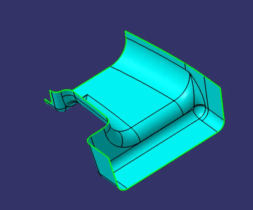
Tooling axis and Draft analysis-
The white dotted line perpendicular to the class-A surface is our tooing axis.
Class-A Draft ananlysis due to class a surface has some issue so it can't be properly cleared in draft.
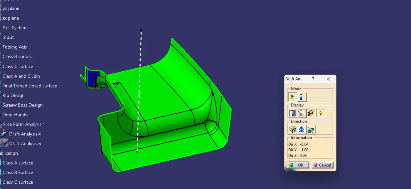
Created class-B surface and then class-C surface joined class-A and C surface togather and then trimmed it with class-B surface to form a final closed surface.
In part workbench used close body command to create a solid part from the closed surface-
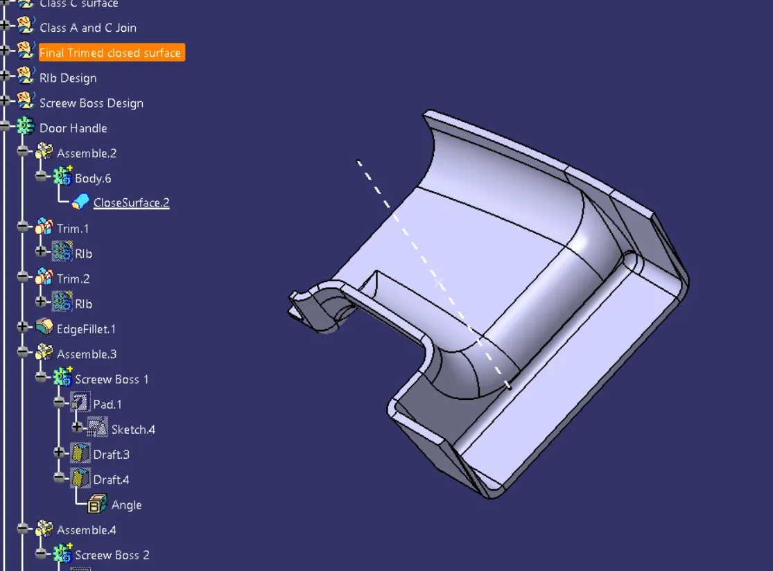
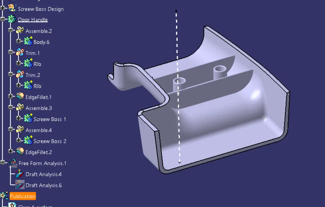
After creating close body I created the rib 1 as per the rib guidelines with thick command in part workbench and then translated it at a distance of 19mm to create rib 2-
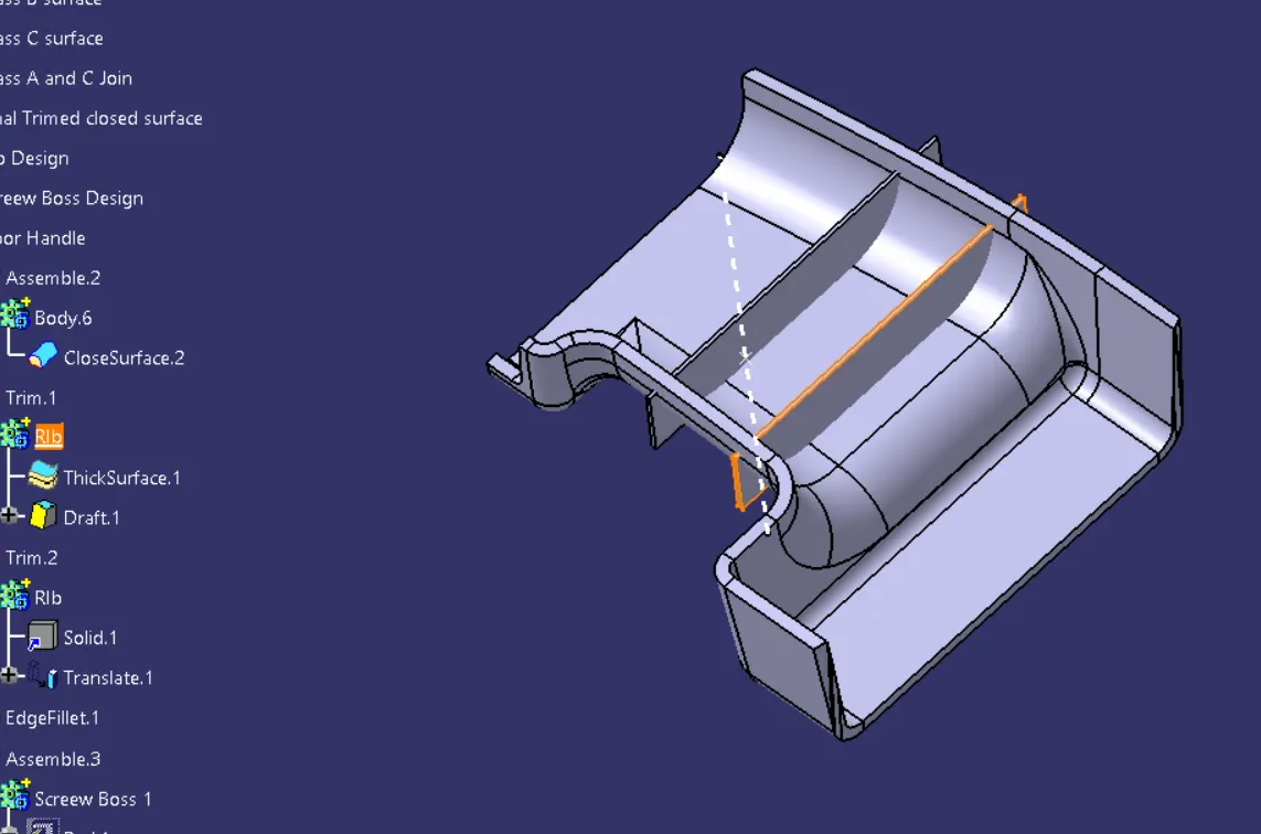
Screew Boss Design-
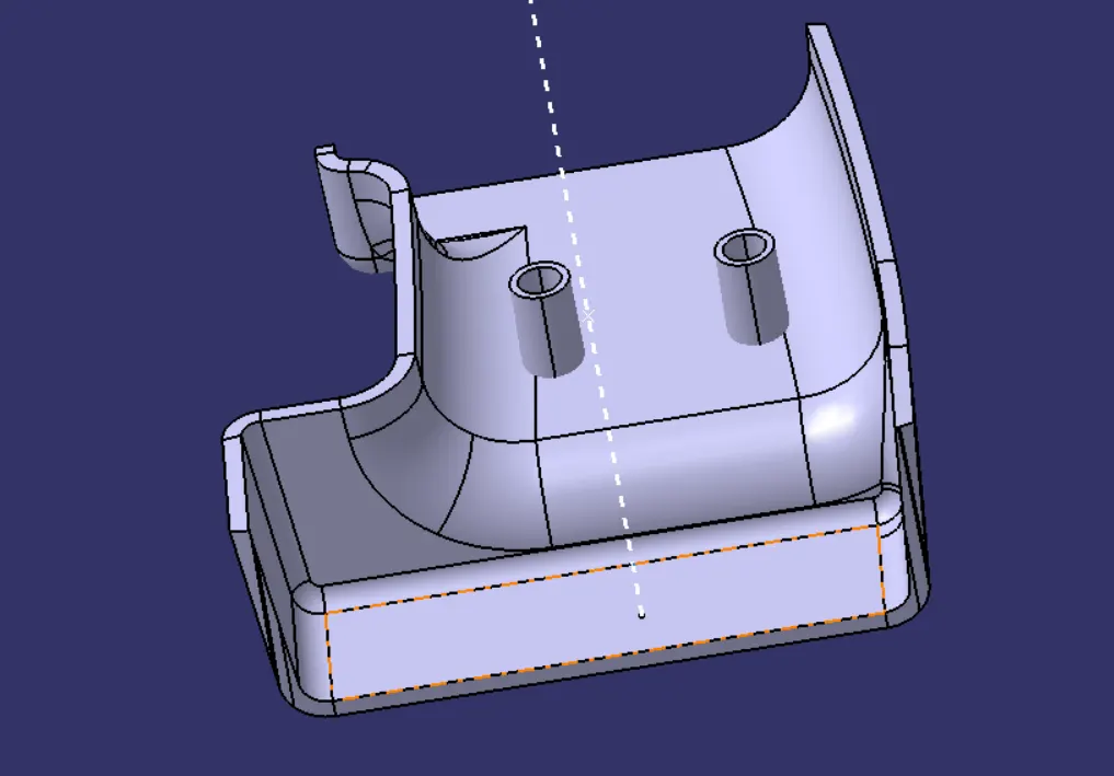
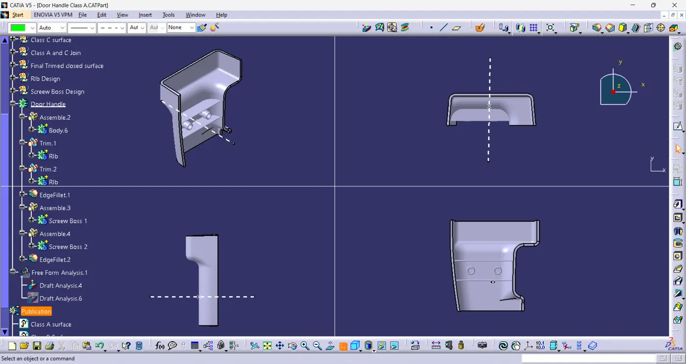
Complete door handle with B-side features-
Screenshots of the completed design in various orientations (Isometric, Front, Side, and Top View)-
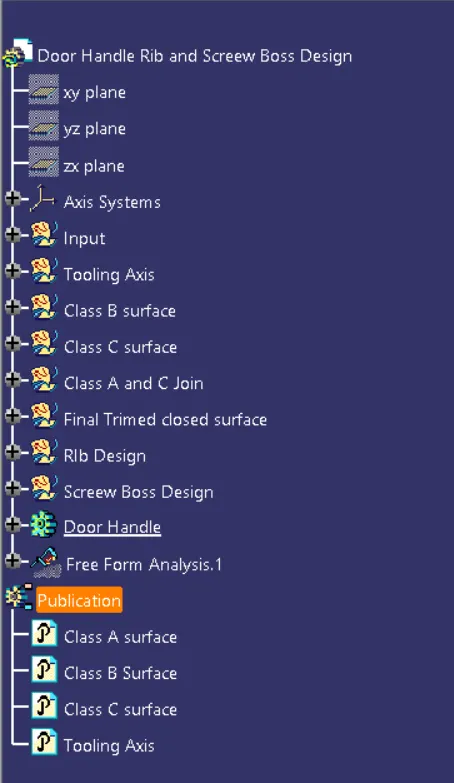
Specification tree structure:-
NOTE:
- Sketches
- Use Positioned sketch
- Sketches should be Iso-Constrained
- Tree Structure
- Ensure Proper Tree Structure
- Geometrical sets should have a proper name based on the sketches present inside of it
- All the sketches should be created under the Geometrical set
- Report
- A detailed report should be done explaining the draft analysis and the tooling axis creation.
- An explanation should be given on the way of creating the tooling axis, particularly the Bisecting method.
- Reference
- Refer to the below-given image to understand the position of the Screw Boss and Ribs
While working on this challenge I learned to create ribs and screw boss with all the guidelines followed for a plastic component. All the above rules have been followed while working on the challenge.